Sélection de la langue

Search

Sommaire du brevet 2797113 

Énoncé de désistement de responsabilité concernant l'information provenant de tiers

Une partie des informations de ce site Web a été fournie par des sources externes. Le gouvernement du Canada n'assume aucune responsabilité concernant la précision, l'actualité ou la fiabilité des informations fournies par les sources externes. Les utilisateurs qui désirent employer cette information devraient consulter directement la source des informations. Le contenu fourni par les sources externes n'est pas assujetti aux exigences sur les langues officielles, la protection des renseignements personnels et l'accessibilité.

Disponibilité de l'Abrégé et des Revendications

L'apparition de différences dans le texte et l'image des Revendications et de l'Abrégé dépend du moment auquel le document est publié. Les textes des Revendications et de l'Abrégé sont affichés :

  • lorsque la demande peut être examinée par le public;
  • lorsque le brevet est émis (délivrance).
(12) Demande de brevet: (11) CA 2797113
(54) Titre français: POMPE A ORIFICE DE DEGONFLAGE INTEGRE
(54) Titre anglais: PUMP WITH INTEGRATED DEFLATION PORT
Statut: Réputée abandonnée et au-delà du délai pour le rétablissement - en attente de la réponse à l’avis de communication rejetée
Données bibliographiques
(51) Classification internationale des brevets (CIB):
  • F04D 25/08 (2006.01)
  • A47C 27/08 (2006.01)
  • F04D 29/40 (2006.01)
(72) Inventeurs :
  • COLEMAN, BRIAN (Etats-Unis d'Amérique)
  • WEN, VINCENT (Taïwan, Province de Chine)
(73) Titulaires :
  • THE COLEMAN COMPANY, INC.
(71) Demandeurs :
  • THE COLEMAN COMPANY, INC. (Etats-Unis d'Amérique)
(74) Agent: BORDEN LADNER GERVAIS LLP
(74) Co-agent:
(45) Délivré:
(86) Date de dépôt PCT: 2011-04-20
(87) Mise à la disponibilité du public: 2011-10-27
Requête d'examen: 2016-04-06
Licence disponible: S.O.
Cédé au domaine public: S.O.
(25) Langue des documents déposés: Anglais

Traité de coopération en matière de brevets (PCT): Oui
(86) Numéro de la demande PCT: PCT/US2011/033261
(87) Numéro de publication internationale PCT: US2011033261
(85) Entrée nationale: 2012-10-22

(30) Données de priorité de la demande:
Numéro de la demande Pays / territoire Date
12/765,653 (Etats-Unis d'Amérique) 2010-04-22

Abrégés

Abrégé français

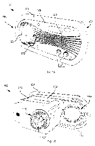
Une pompe pour dispositif gonflable comprend un boîtier qui délimite une chambre de soufflerie conçue pour être introduite dans le dispositif gonflable. La chambre de soufflerie comprend un orifice d'évacuation conçu pour communiquer l'air hors de la pompe. Le boîtier délimite également un orifice de dégonflage, qui est adjacent à la chambre de soufflerie, et une partie de fixation conçue pour créer un joint sensiblement étanche à l'air avec la surface du dispositif gonflable. La pompe comprend également un couvercle à fixation amovible conçu pour recouvrir sensiblement la chambre de soufflerie. Le couvercle délimite une ouverture par laquelle s'étend l'orifice de dégonflage, et au moins un évent par lequel l'air est communiqué dans la pompe.


Abrégé anglais

A pump for an inflatable device includes a housing that defines a blower chamber configured to be inserted into the inflatable device. The blower chamber includes an exhaust port configured to communicate air out of the pump. The housing also defines a deflation port, which is adjacent to the blower chamber, and an attachment portion configured to make a substantially airtight seai with the surface of the inflatable device. The pump also includes a removabiy attachable cover configured to substantially cover the blower chamber. The cover defines an opening through which the deflation port extends, and at least one vent through which air is communicated into the pump.

Revendications

Note : Les revendications sont présentées dans la langue officielle dans laquelle elles ont été soumises.


CLAIMS
We claim:
1 . A pump for an inflatable device comprising:
a housing that defines:
a blower chamber configured to be inserted into said inflatable device,
said blower chamber includes an exhaust port configured to communicate air
out of said pump
a deflation port disposed adjacent to said blower chamber, and
an attachment portion configured to make a substantially airtight seat
with a surface of said inflatable device; and
a cover removably attached to said housing configured to substantially cover
said blower chamber, wherein said cover defines an opening through which said
deflation port extends, and at least one vent that is spaced apart from said
opening
through which air is communicated into said pump.
2. The pump according to claim 1, further comprising a blower housing
configured to be removably attached to said cover, wherein said blower housing
is
disposed in said blower chamber and is configured to communicate air from said
at
least one vent to said exhaust port.
3. The pump according to claim 2, wherein said blower housing comprises a
motor.
4. The pump according to claim 3, wherein said blower housing comprises an
impeller.
5. The pump according to claim 1, wherein said blower housing includes an
outlet port configured to engage said exhaust port to form a substantially air
tight
seal between said blower housing and said exhaust port.
6. The pump according to claim 1 further comprising a deflation port cap
configured to cover said deflation port.
7

7. The pump according to claim 6, further comprising locking members on said
deflation port cap and complementary locking members on said deflation port.
8. The pump according to claim 6; wherein said deflation port comprises a
valve
configured to substantially prevent air in said inflatable device from
escaping through
said deflation port when said deflation cap is removed,
9. The pump according to claim 8, wherein said valve is configured to be
selectively locked in an open position to enable air from said inflatable
device to
escape through said deflation port.
10. The pump according to claim 1, further comprising a pressure regulator
disposed in said blower chamber.
11. The pump according to claim 1, wherein said exhaust port comprises a valve
configured to substantially prevent air in said inflatable device from
escaping through
said exhaust port.
12. The pump according to claim 1, wherein said exhaust port is removably
attached to said blower chamber.
13. The pump according to claim 1, further comprising fastening means on said
cover for fastening said motor to said cover.
14. A method for manufacturing a pump for an inflatable device comprising:
providing a housing that defines:
a blower chamber configured to be inserted into said inflatable device,
said blower chamber includes an exhaust port configured to communicate air
out of said pump
a deflation port disposed adjacent to said blower chamber, and
an attachment portion configured to make a substantially airtight seal
with a surface of said inflatable device: and
attaching a removably attachable cover to said housing, wherein said
removably attachable cover is configured to substantially cover said blower
chamber,
8

wherein said cover defines an opening through which said deflation port
extends,
and at least one vent through which air is communicated into said pump,
15. The method according to claim 14, further comprising inserting a motor
into
said blower chamber, wherein said motor is configured to communicate air from
said
at least one vent to said exhaust port,
16. The method according to claim 14 further comprising providing a deflation
port
cap configured to cover said deflation port.
17. The method according to claim 16, further comprising providing locking
members on said deflation port cap and complementary locking members on said
deflation port.
18. The method according to claim 16, wherein said deflation port comprises a
valve configured to substantially prevent air in said inflatable device from
escaping
through said deflation port when said deflation cap is removed,
19. The method according to claim 18, wherein said valve is configured to be
selectively locked in an open position to enable air from said inflatable
device to
escape through said deflation port.
20. The method according to claim 14, further comprising inserting a pressure
regulator in said blower chamber.
9

Description

Note : Les descriptions sont présentées dans la langue officielle dans laquelle elles ont été soumises.


CA 02797113 2012-10-22
WO 2011/133676 PCT/US2011/033261
PUMP WITH INTEGRATED DEFLATION PORT
BACKGROUND
1. Field
[0001] The present invention relates generally to pumps, More specifically,
the
present invention relates to a pump with an integrated deflation valve.
il. Description of Related Art
100021 Inflatable mattresses have become popular due to their utility as an
extra
bed needed around the house or on camping trips. An advantage of such
inflatable
mattresses is that they are portable and easily stored. A pump is typically
required
to fill these mattresses quickly and efficiently. For example, a battery-
operated or
corded pump may be provided with the mattress and adapted to fill the mattress
with
air. In some cases, the pump is integrated into the air mattress. In this
case, the
perimeter of the pump is glued or welded to the mattress. To facilitate
deflation of
the mattress, a separate deflation port is also glued or welded to the
mattress.
[00031 However, the increase in the number of items glued and/or welded to the
mattress increases the manufacturing costs of the mattress and increases the
chances of a leak developing.
SUMMARY
[0004] An embodiment of a pump for an inflatable device includes a housing
that
defines a blower chamber configured to be inserted into the inflatable
device., The
blower chamber includes an exhaust port configured to communicate air out of
the
pump. The housing also defines a deflation port, which is adjacent to the
blower
chamber, and an attachment portion configured to make a substantially airtight
seal
with the surface of the inflatable device. The pump also includes a removably
attachable cover configured to substantially cover the blower chamber. The
cover
defines an opening through which the deflation port extends, and at least one
vent
through which air is communicated into the pump.
BRIEF DESCRIPTION OF THE DRAWINGS
[0006) The accompanying drawings are included to provide a further
understanding of the invention and are incorporated in and constitute a part
of this
specification. The detailed description and illustrated embodiments of the
invention
serve to explain the principles of the invention,
I

CA 02797113 2012-10-22
WO 2011/133676 PCT/US2011/033261
[0006] Figs. 1A and 1 B illustrate a front and rear perspective views,
respectively,
of a pump for an inflatable device;
[0007] Fig. 2A illustrates a deflation port and deflation port cover of the
pump of
Fig. 1;
[0008] Fig. 2B illustrates details of the deflation port;
[0009] Fig. 3 illustrates the pump of Fig. 1 in a partially disassembled
state;
[0010] Fig. 4A illustrates a pump cover and blower of the pump of Fig. 1;
(0011] Fig. 4B illustrates the pump cover; and
[0012] Fig. 5 illustrates the pump of Fig. I integrated into an inflatable
device;
DETAILED DESCRIPTION
[0013] Figs. 1A and 1 B illustrate front and rear perspective views,
respectively, of
a pump 100 for an inflatable device 503 (Fig. 5), such as an inflatable air
mattress or
other inflatable support device. The pump 100 includes a housing 102 that
defines a
blower chamber 110, a deflation port 140, and an inflatable device attachment
portion 105, hereinafter referred to as the attachment portion 105. The pump
100
also includes a cover 125.
[0014] The attachment portion 105 is configured to form a substantially
airtight
seal with the surface of the inflatable device 500. The attachment portion 105
may
be glued or welded to the surface of the inflatable device 500 or may be
fastened to
the inflatable device 500 in a different way that produces a substantially
airtight seal
between the pump 100 and the inflatable device 500.
[0015] The blower chamber 110 of the pump 100 is configured to be inserted
into
the inflatable device 500 such that the blower chamber 110 is substantially
disposed
inside the inflatable device 500, as illustrated in Fig. 5.
[0016] Referring to Fig. 3, the blower chamber 110 defines a cavity 310
configured to house a blower housing 305. As shown in Fig. 4A, the blower
housing
305 may comprise an impeller 410, an AC or DC electric motor 415, an air inlet
420,
and an air outlet 425. The electric motor 415 may be coupled to the impeller
410 via
a shaft (not shown),. The blower housing 305 is configured to communicate air
from
vents 129 defined by the cover 125 to an exhaust port 115 (Fig. 1) of the
blower
chamber 110. to pressurize the inflatable device 500 with enough pressure to
enable
2

CA 02797113 2012-10-22
WO 2011/133676 PCT/US2011/033261
the support of an object, such as a person. Air is drawn into the blower
housing 305
via the air inlet 420 and exits the blower housing 305 via the air outlet 425.
The air
outlet 420 is configured to form a substantially air tight seal with the
exhaust port
115, which may include a receiving portion 312 (Fig. 3) that is configured to
be
complementary to the air outlet 420,
[0017) Referring back to Fig. 1, the exhaust port 115 is configured to
communicate air generated by the blower housing 305 into an internal space
defined
by the inflatable device 500. In some implementations, the exhaust port 115 is
configured to provide unidirectional air flow into the inflatable device 500.
For
example, the exhaust port 115 may include a valve membrane 103 that deflects
to
allow air to move into the inflatable device 500 and seals against a surface
to
prevent air from escaping from the inflatable device 500. A grill may be
disposed
around the valve to prevent mechanical interference with the valves operation.
The
valve may comprise a flexible material, such a rubber, silicone, or a
different material
capable of performing the function of the valve. The valve 115 is configured
to be
removably attached to the blower chamber 310. In some implementations, the
valve
is inserted into the blower cavity 310, pushed into an opening defined by the
blower
chamber 110 and twisted to secure the valve 115 to the blower chamber 110. The
valve may be removed by reversing these steps.
(0018] In some implementations, a pressure regulator (not shown) may be
disposed within the blower chamber 110. The pressure regulator is configured
to
interrupt power to the motor 415 of the blower housing 305 when a desired air
pressure is achieved inside of the inflatable device 500. The pressure
regulator may
be removably attached to the blower chamber 110 to enable removal of the
pressure
regulator.
(0019] The deflation port 140 of the housing 102 may be positioned adjacent to
the blower chamber 110. The deflation port 140 enables the deflation of the
inflatable device 500. In some implementations, a detachable deflation port
cap 120
may be secured to the deflation port 140 to prevent air from escaping from the
inflatable device 500.
[0020] At least one advantage to providing a housing with a unified blower
chamber 110 and deflation port 140 is that it minimizes the number of items
glued or
3

CA 02797113 2012-10-22
WO 2011/133676 PCT/US2011/033261
welded to the inflatable device 500, thereby decreasing the costs associated
with
manufacturing the inflatable device 500. Another advantage of a housing with a
unified blower chamber 110 and deflation port 140 is that the surface area for
the
associated attachment portion 105 is less than the surface area for respective
attachment portions of a comparably sized non-unified blower chamber and
deflation
port. The decreased surface area lowers the likelihood of a leak developing in
the
inflatable device 500 in the vicinity of the pump 100.
[0021] Referring to Figs. 2A and 2B, the deflation port cap may include
locking
members 120a that are configured to engage complementary locking members 140a
on the deflation port 140. In some implementations, the deflation port cap 120
may
include a seal 120b, such as a rubber o-ring, to improve the air-tightness
between
the deflation port 140 and the deflation port cap 120. In yet other
implementations,
the deflation port cap 120 is tethered to the deflation port 140 to prevent
misplacement of the deflation port cap 120. The deflation port cap 120 and/or
the
deflation port 140 may each define an aperture (not shown) for securing the
tether
130,
[0022] In some implementations, the deflation port 140 includes a valve 140b,
as
shown in Fig. 2B. The valve 14Db is configured to substantially prevent air in
the
inflatable device 500 from escaping through the deflation port 140 when the
deflation
cap 120 is removed. The valve 140b may comprise a flexible material, such as
rubber, silicone, or a different material and is configured to form a
substantially
airtight seal with an inner surface of the deflation port 140 when the air
pressure
inside the inflatable device is greater than the surrounding air pressure. The
valve
140b is opened by pushing the valve 140b in an inward direction. In some
implementations, the valve 140b is configured to be selectively locked in an
open
position by pushing the valve 14Db over retention members 142 of the deflation
port
140, as illustrated in Fig. 1 B. The valve 140b may include a member 140c that
enables returning the valve to a closed position.
[0023] Referring to Fig. 3, the cover 125 is configured to be removably
attached
to the housing 102 via fasteners, such as screws, or may be removable attached
in a
different manner. For example, the cover 125 and/or housing 102 may include
locking members that enable snapping the cover 125 into place. The cover 125
is
configured to substantially cover the cavity 310 defined by the blower chamber
110.
4

CA 02797113 2012-10-22
WO 2011/133676 PCT/US2011/033261
The cover 125 may define one or more vent openings 129 through which air is
communicated into the blower chamber `110, and an opening 127 through which
the
deflation port 140 extends.
[0024] As illustrated in Figs. 4A and 4B, the cover 125 may include one or
more
bosses 405 that enable fastening the blower housing 305 to the cover 125. For
example, the blower housing 305 may be fastened to the cover 125 via screws
that
enable removal of the blower housing 305 for servicing. Releasable connectors
may
be utilized to connect the motor to other circuits so that the blower housing
305 may
be easily removed. Once fastened, the cover 125 with the fastened blower
housing
305 may be fastened to the housing 102,
[00251 At least one advantage to providing a removably attached cover is that
it
enables placement or replacement of the blower housing 305 and other
components
that are disposed within the blower chamber 110 without the destruction of the
inflatable device 500. For example, during manufacturing, the housing 102 may
be
inserted and fastened to the inflatable device 500 in a first manufacturing
operation.
Then components of the pump 100 may be inserted into the blower chamber 110.
O service the inflatable device 500, the cover may be removed to expose the
blower
housing 110, the valve 115, pressure regulator, and other components disposed
within the blower chamber 110. The respective components may then be serviced.
[00261 Another advantage to providing a removably attached cover 125 is that
the
cover 125 may be customized independent of the other components of the pump.
For example, pump housings may be attached to inflatable devices in a first
manufacturing operation. During later operations, the inflatable devices with
the
attached housings may be differentiated via customized cover plates. For
example,
an OEM manufacture may select a cover design based on a customer.
[0027] While the method and system has been described with reference to
certain embodiments, it will be understood by those skilled in the art that
various
changes may be made and equivalents may be substituted without departing from
the scope. In addition, many modifications may be made to adapt a particular
situation or material to the teachings without departing from its scope.
Therefore, it
is intended that the present method and system not be limited to the
particular

CA 02797113 2012-10-22
WO 2011/133676 PCT/US2011/033261
embodiment disclosed, but that the method and system include all embodiments
falling within the scope of the appended claims.
6

Dessin représentatif
Une figure unique qui représente un dessin illustrant l'invention.
États administratifs

2024-08-01 : Dans le cadre de la transition vers les Brevets de nouvelle génération (BNG), la base de données sur les brevets canadiens (BDBC) contient désormais un Historique d'événement plus détaillé, qui reproduit le Journal des événements de notre nouvelle solution interne.

Veuillez noter que les événements débutant par « Inactive : » se réfèrent à des événements qui ne sont plus utilisés dans notre nouvelle solution interne.

Pour une meilleure compréhension de l'état de la demande ou brevet qui figure sur cette page, la rubrique Mise en garde , et les descriptions de Brevet , Historique d'événement , Taxes périodiques et Historique des paiements devraient être consultées.

Historique d'événement

Description Date
Inactive : COVID 19 - Délai prolongé 2020-03-29
Demande non rétablie avant l'échéance 2019-04-03
Inactive : Morte - Taxe finale impayée 2019-04-03
Réputée abandonnée - omission de répondre à un avis sur les taxes pour le maintien en état 2018-04-20
Réputée abandonnée - les conditions pour l'octroi - jugée non conforme 2018-04-03
Un avis d'acceptation est envoyé 2017-10-03
Lettre envoyée 2017-10-03
Un avis d'acceptation est envoyé 2017-10-03
Inactive : Q2 réussi 2017-09-27
Inactive : Approuvée aux fins d'acceptation (AFA) 2017-09-27
Modification reçue - modification volontaire 2017-08-09
Inactive : Dem. de l'examinateur par.30(2) Règles 2017-02-09
Inactive : Rapport - CQ réussi 2017-02-08
Lettre envoyée 2016-04-15
Exigences pour une requête d'examen - jugée conforme 2016-04-06
Toutes les exigences pour l'examen - jugée conforme 2016-04-06
Requête d'examen reçue 2016-04-06
Inactive : Page couverture publiée 2013-01-28
Inactive : Demandeur supprimé 2013-01-21
Inactive : Notice - Entrée phase nat. - Pas de RE 2013-01-21
Inactive : CIB en 1re position 2012-12-11
Inactive : CIB attribuée 2012-12-11
Demande reçue - PCT 2012-12-11
Exigences pour l'entrée dans la phase nationale - jugée conforme 2012-10-22
Demande publiée (accessible au public) 2011-10-27

Historique d'abandonnement

Date d'abandonnement Raison Date de rétablissement
2018-04-20
2018-04-03

Taxes périodiques

Le dernier paiement a été reçu le 2017-03-31

Avis : Si le paiement en totalité n'a pas été reçu au plus tard à la date indiquée, une taxe supplémentaire peut être imposée, soit une des taxes suivantes :

  • taxe de rétablissement ;
  • taxe pour paiement en souffrance ; ou
  • taxe additionnelle pour le renversement d'une péremption réputée.

Les taxes sur les brevets sont ajustées au 1er janvier de chaque année. Les montants ci-dessus sont les montants actuels s'ils sont reçus au plus tard le 31 décembre de l'année en cours.
Veuillez vous référer à la page web des taxes sur les brevets de l'OPIC pour voir tous les montants actuels des taxes.

Historique des taxes

Type de taxes Anniversaire Échéance Date payée
Taxe nationale de base - générale 2012-10-22
TM (demande, 2e anniv.) - générale 02 2013-04-22 2013-04-05
TM (demande, 3e anniv.) - générale 03 2014-04-22 2014-04-11
TM (demande, 4e anniv.) - générale 04 2015-04-20 2015-04-07
Requête d'examen - générale 2016-04-06
TM (demande, 5e anniv.) - générale 05 2016-04-20 2016-04-20
TM (demande, 6e anniv.) - générale 06 2017-04-20 2017-03-31
Titulaires au dossier

Les titulaires actuels et antérieures au dossier sont affichés en ordre alphabétique.

Titulaires actuels au dossier
THE COLEMAN COMPANY, INC.
Titulaires antérieures au dossier
BRIAN COLEMAN
VINCENT WEN
Les propriétaires antérieurs qui ne figurent pas dans la liste des « Propriétaires au dossier » apparaîtront dans d'autres documents au dossier.
Documents

Pour visionner les fichiers sélectionnés, entrer le code reCAPTCHA :


Pour visualiser une image, cliquer sur un lien dans la colonne description du document. Pour télécharger l'image (les images), cliquer l'une ou plusieurs cases à cocher dans la première colonne et ensuite cliquer sur le bouton "Télécharger sélection en format PDF (archive Zip)" ou le bouton "Télécharger sélection (en un fichier PDF fusionné)".

Liste des documents de brevet publiés et non publiés sur la BDBC .

Si vous avez des difficultés à accéder au contenu, veuillez communiquer avec le Centre de services à la clientèle au 1-866-997-1936, ou envoyer un courriel au Centre de service à la clientèle de l'OPIC.


Description du
Document 
Date
(aaaa-mm-jj) 
Nombre de pages   Taille de l'image (Ko) 
Description 2012-10-21 6 316
Revendications 2012-10-21 3 118
Dessins 2012-10-21 5 126
Abrégé 2012-10-21 2 78
Dessin représentatif 2013-01-21 1 18
Dessins 2017-08-08 5 125
Description 2017-08-08 6 283
Revendications 2017-08-08 3 91
Rappel de taxe de maintien due 2013-01-20 1 111
Avis d'entree dans la phase nationale 2013-01-20 1 193
Rappel - requête d'examen 2015-12-21 1 117
Accusé de réception de la requête d'examen 2016-04-14 1 176
Avis du commissaire - Demande jugée acceptable 2017-10-02 1 162
Courtoisie - Lettre d'abandon (AA) 2018-05-14 1 164
Courtoisie - Lettre d'abandon (taxe de maintien en état) 2018-05-31 1 171
PCT 2012-10-21 10 379
Requête d'examen 2016-04-05 1 34
Demande de l'examinateur 2017-02-08 3 185
Modification / réponse à un rapport 2017-08-08 14 466