Note : Les descriptions sont présentées dans la langue officielle dans laquelle elles ont été soumises.
CA 02797443 2015-05-06
- 1 -
MULTI-SLAT COMBINATION BLIND OF ROTATING TYPE
FIELD OF THE INVENTION
The present invention relates to a kind of blind structure for blocking or
guiding light, specifically, relates to a kind of multi-slat combination blind
of
rotating type.
BACKGROUND OF THE INVENTION
Louver allows too much sunlight into room near window, resulting in glare
near the window and indoor overheat, but insufficient bright at deep room. It
is
impossible to bright a big office evenly by natural light with commercial
blinds
available in current market. In sunshine day, sunlight is kept out to reduce
the
light and heat, which causes office too dark, and artificial lighting has to
be
used to get bright enough illumination. That results in more energy expense,
people's uncomfortableness and lower work efficiency. Therefore, a new kind
of sun-shading and light-guiding blind is invented. This invention can
anti-glare and prevent overheating as commercial blind, also guide the
sunlight into deep room, which makes the room lighted by sunlight evenly, and
heated by sunlight in winter to reduce the heating costs.
Generally speaking, sun-shading and light-guide blind may be divided
into upper and lower two parts (usually the boundary between upper and
lower part takes human-height as benchmark, which is 1.9m in West and
1.8m in Asia properly), the louver rotating gradient of these two parts may be
dependent or independent. Usually the lower louver may be set as anti-glare
and prevention overheating, and the upper louver may be set to import the
light into deep room. Besides increasing design cost, this system has a fault -
the functions of two parts, anti-glare or guiding light, are defined in
advance,
therefore cannot be adjusted according to users, seasons and specific lighting
CA 02797443 2012-10-25
- 2 -
condition of workplace.
Indoor illumination condition depends upon not only seasons, sun
position, sky condition (cloudy or sunny), but also working condition, such as
work types, height, work location, and distance from the window. Obviously,
sun-shading and light-guiding blind defined by architects and architectural
lighting engineers cannot meet all said requirements but a compromise
among them. In addition, the costs of design and blind are increased seriously
if different blinds were installed for different situations.
European patent (EP0400662B1) publishes a sun-shading blind,
including outside and inside parts. They are linked by rotating shaft; and
their
activities are controlled by rope respectively. Outside part can block
sunlight
to outdoor by rotating to special position, and inside part can guide sunlight
to
deep room if necessary. Based on EP0400662B1, Germany patent
(DE29814826U1) introduces artificial fiber hinged film brackets whose shapes
are close to each slat's radian shape. Rope can easily control two slats'
rotation around hinge. Germany patent (DE10147523A1) makes improvement
on the rope control structure based on European patent (EP040066261),
finding a better rope control structure for blind. However, these patents did
not
consider the combination blind's transparency, retro-reflection, deflection
light
guiding and optimal light adjustment according to personalize demands for
sunlight.
European patent (EP1212508B1) describes a blind with differently
shaped slats, with toothed or smooth surface. The curved slat with teeth and
the W-shaped slat showed excellent properties respectively on retro-
reflection,
light-guiding and transparency. The transparency of W-shaped blind can
reach 74%, while that of curved blind with teeth can reach 88%. But these
blinds cannot meet the above season changing and specific needs - Blind is
demanded to keep higher transparency while low solar elevation angle, and
while more sunlight is required to guide into room, the blind has to be close
to
prevent glare.
German patent (DE10016587A1) introduces V-shaped and W-shaped
advertising shutter. Transparency of such fixed shutter is about 56%. It
reflects a part of sunlight back to the outdoor space to avoid overheating and
glare, and guides some sunlight into deep room to make the whole room
CA 02797443 2012-10-25
- 3 -
illuminated evenly. However such fixed shutter has two problems: 1. sunlight
gets into the indoor space when solar elevation angle is lower than 25 degree,
incurring glare , hence another scroll window shade should be installed to
keep out the sunlight in such case; 2. to guide part of sunlight around some
range of solar elevation angle into the indoor space to light up whole room
regardless of season or other specific factors may cause the indoor space too
bright and overheating.
SUMMARY OF THE INVENTION
Technical problem to be solved by this invention: a kind of multi-
V-shaped slats combination blind, which can optimize blocking or guiding
sunlight flexibly according to different seasons, weather conditions, and
personalized demands, can illuminate room evenly by natural sunlight, avoid
glare, avoid overheating in summer, and obtain more solar energy for indoor
heating in winter.
The specific techniques in this invention are as follows:
A multi-slat combination blind of rotating type consists of main slats and
rotating slats. Main slat is composed of the outside part and the inside part,
joint section is the edge of the outside part meets that of the inside part at
the
width direction. The included angle between the outside part and the
horizontal plane is 7, , and the included angle between the inside part and
the
horizontal plane is 72 . The rotating slat is hinged above the main slat,
which
is driven by the mechanism system.
Two rotating slats as mentioned above wherein the first rotating slat and
the second rotating slat are hinged at any position above the main slat.
The cross section of said main slat is symmetrically V-shaped, and the
rotating slat is hinged at the bottom of V-shape of the main slat.
The cross section of said main slat is asymmetrically V-shaped.
The cross section of said outside part and inside part of the main slat is
arc.
The cross section of said main slat, whereof the outside part is plane, and
the inside part is arc.
The included angle between said outside part of the main slat and the
CA 02797443 2012-10-25
-4 -
horizontal plane is - 35 _C. 35 . Anticlockwise is positive, and clockwise
is
negative.
The included angle between said inside part of the main slat and the
horizontal plane is - 35 y2 35 . Anticlockwise is positive, and clockwise is
negative.
The included angle between said outside part of the main slat and the
horizontal plane is - 90 0 . Anticlockwise is positive, and clockwise is
negative.
The included angle between said inside part of the main slat and the
horizontal plane is 00 r2 90 . Anticlockwise is positive, and clockwise is
negative.
The said multi-slat blind has sun-shading slat that is set under the main
slat and may be furled close to the underside of the main slat, and can be
spread to block or retro-reflect part of sunlight back to the outdoor space
when
solar elevation angle is low in winter and summer.
The said multi-slat blind has roller blind that is located at outside of slat.
The roller blind shaft can be installed horizontally or vertically, and can
furl
inside window frame. The roller blind slat consists of hollow and non-hollow
two parts, and the height of hollow part is 1/2 or 2/3 of blind pitch D. Pitch
D is
the space between edges c on the indoor space of two adjacent main slats.
The roller blind can be spread to block or retro-reflect part of sunlight to
the
outdoor space when solar elevation angle is low in winter and summer.
A V-shaped advertising bracket is set at the underside of the main slat,
and sun-shading component is installed on the bottom of V-shaped
advertising bracket.
The upper side of the main slat is covered by micro-teeth partly or wholly.
The first and the second surfaces of the rotating slat are covered by
micro-teeth partly or wholly.
The micro-teeth on the upper side of the main slat may be different types.
The micro-teeth on both sides of the rotating slat may be different types.
The micro-teeth of the said are retro-reflection teeth, including two
adjacent orthogonal surfaces: the first tooth surface and the second tooth
surface. The variation range of included angle aH between the second tooth
CA 02797443 2012-10-25
- 5 -
surface, which plays a role of retro-reflecting to sunlight, and the
horizontal
plane is 90 -(fiw +H)/ 2 5_ ctii 90* -( At, +H)/2
, wherein H is solar
elevation angle, fiiõ, is the included angle between the line, linking any
edge
on the upper side of the slat and the edge on the outdoor space of the
underside of the adjacent upper slat, and the horizontal plane, /3. is the
included angle between the line, linking any edge on the upper side of the
slat
and the edge on the outdoor space, and the horizontal plane.
The said micro-teeth are forward or backward teeth, which includes two
adjacent orthogonal surfaces: the first and the second tooth surface. The
variation range of included angle a, between the second tooth surface,
which plays a role of guiding direct light into room, and the horizontal plane
is
-H)/ 2 5.. aH -H)/2, wherein H
is solar elevation angle, iik is the
included angle between the line, linking any edge on the upper side of a slat
and the edge on the indoor space of the slat, and the horizontal plane, fl,.
is
the included angle between the line, linking any edge on the upper side of a
slat and the edge on the indoor space of the underside of the adjacent upper
slat, and the horizontal plane.
The uniqueness of the invention: all kinds of blinds - sun-shading and
light-guiding system composed of any V-shaped rotating multi-slat, can
optimize blocking and guiding sunlight according to different seasons and
personalized requirements, can fit different demands for sunlight in summer
and winter, can keep high transmission either with high or low solar elevation
angle to satisfy people's visual needs - good view through window. Current
commercial blinds have to be adjusted frequently according to solar elevation
angle changing in daytime while these new sunlight self-adapting blinds only
can be operated twice a day, which is benefit for intelligent control. Combine
multi-slat blind of rotating type and V-shaped advertising bracket to take the
place of traditional advertising curtain wall. Traditional advertising curtain
wall
blocks light and wind while new designed advertising blind can solve such
problem so that room behind it can obtain natural ventilation, good viewing,
and sunlight illumination.
CA 02797443 2012-10-25
- 6 -
BRIEF DESCRIPTION OF THE DRAWINGS
Fig.1 a-Fig.1c Cross section of symmetrical V-shaped blind, angles and
dimensions definition (- 35 5_ y, 5_ 35 ,- 35 5 y2 .5 35 ),
Fig.2a-Fig.2d Schematic diagrams of action and sunlight reflection of two
symmetrical V-shaped slats blind (-35 5_ y, 5.35 , -35 5 y2 35 over 1.8m
above indoor ground) according to different solar elevation angle,
Fig.3a-Fig.3d Schematic diagrams of action and sunlight reflection of two
symmetrical V-shaped slats blind (-35 5 y, 5 35 , - 35 5 y2 _C. 35 below
1.8m
above indoor ground) according to different solar elevation angle,
Fig.4a-Fig.4d Schematic diagrams of action and sunlight reflection of
three symmetrical V-shaped slats blind (-35 5 y, 5_ 35 , - 35 572 35 over
1.8m above indoor ground) according to different solar elevation angle,
Fig.5a-Fig.5d Schematic diagrams of action and sunlight reflection of
three symmetrical V-shaped slats blind (-35 5 y, 5 35 , -35 5 y2 _5 35
below
1.8m above indoor ground) according to different solar elevation angle,
Fig.6a-Fig.6d Definition of micro-teeth type and tooth face angles on .
curved surface that retro-reflects and guides sunlight,
Fig.7a-Fig7d Schematic diagram of two-slat combination blind,
symmetrical V-shape (-35' 5y, ..35 , -35 .. y2 5_35 ) and asymmetrical V-
shape
(05y, 590 , 0 5. y2 .5.90 ),
Fig.8a-Fig.8b Type and distribution of micro-teeth on surface of two
symmetrical V-shaped slats combination blind,
Fig.9a-Fig.9f Type and distribution of micro-teeth on surface of two
line-shaped (plane) slats combination blind,
Fig.10a-Fig.10b Type and distribution of micro-teeth on surface of two
upside down V-shaped slats combination blind,
Fig.11a-Fig.11c Type and distribution of micro-teeth on surface of two
curved slats combination blind,
Fig.12a-Fig.12c Type and distribution of micro-teeth on surface of two
wave-shaped slats combination blind,
Fig.13 Type and distribution of micro-teeth on surface of three
symmetrical V-shaped slats combination blind,
CA 02797443 2015-05-06
- 7 -
Fig.14a-Fig.14d Schematic diagrams of two symmetrical V-shaped
(Ti =-5 , 72 =5 ) slats combination blind retro-reflects and guides sunlight
according to different solar elevation angle H in summer and winter,
Fig.15a-Fig.15b Schematic diagrams of three symmetrical V-shaped
(Ti =-5 , 72 =50) slats combination blind retro-reflects and guides sunlight
according to different solar elevation angle H in summer and winter,
Fig.16a-Fig.16f Six kinds of combinations of asymmetrical V-shaped and
rotating slats for two-slat combination blind,
Fig.17a-Fig.17c Definition of angles for two asymmetrical V-shaped slats
combination blind ( 0, n
Fig.18a-Fig.18d Relation between slats, type and distribution of
micro-teeth on slats, schematic diagrams of action and sunlight reflection of
two asymmetrical V-shaped slats combination blind (ri =-55 , 72=18 over
1.8m above indoor ground) according to different solar elevation angle,
Fig.19a-Fig.19d Relation between slats, type and distribution of
micro-teeth on slats, schematic diagrams of action and sunlight reflection of
two asymmetrical V-shaped slats combination blind (7 =-55
below 1.8m above indoor ground) according to different solar elevation angle,
Fig.20a-Fig.20d Schematic diagrams of two asymmetrical V-shaped
(Ti =-55 72 =18 ) slats combination blind retro-reflects and guides sunlight
according to different solar elevation angle H in summer and winter,
Fig.21a-Fig.21c Three kinds of combinations of two symmetrical
V-shaped slats combination blind and advertising bracket,
Fig.22a-Fig.22c Definition of angles for symmetrical V-shaped blind
(71.. 0, y2 0) with advertising bracket,
Fig.23a-Fig.22c Relation between slats, type and distribution of
micro-teeth on slats, schematic diagrams of action and sunlight reflection of
two symmetrical V-shaped slats combination blind (y, =-18 , 72=18 over
1.8m above indoor ground) with advertising bracket ( y =-55 ,
=18 )according to different solar elevation angle,
Fig.24a-Fig.24d Relation between slats, type and distribution of
micro-teeth on slats, schematic diagrams of action and sunlight reflection of
CA 02797443 2012-10-25
- 8 -
two symmetrical V-shaped slats combination blind ( = -18 , 72 = 18 below
1.8m above indoor ground) with advertising bracket ( =-'55 ,
72 =18 )according to different solar elevation angle,
Fig.25a-Fig.25d Schematic diagrams of two symmetrical V-shaped slats
combination blind ( y, = -18 , 72=18 ) with advertising bracket ( = -55 ,
y2 =18 ) retro-reflects and guides sunlight according to different solar
elevation angle H in summer and winter,
Fig.26a-Fig.26c Three hinge locations between the sun-shading slat and
the main slat,
Fig.27 Horizontal installation of the scroll blind,
Fig.28 Vertical installation of the scroll blind.
DETAILED DESCRIPTION OF THE INVENTION
Referring to the figures and embodiments, the invention is described in
detail as follows.
EMBODIMENT 1
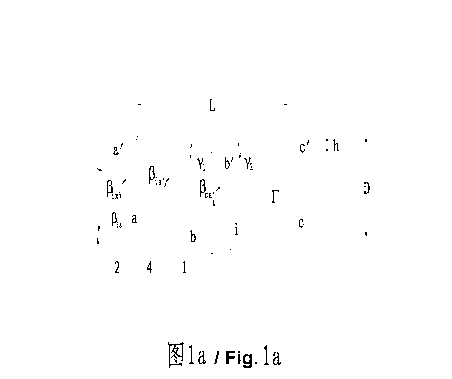
Fig.1 shows cross section (in the width direction) giving definition of
geometric shape, angles and dimensions of symmetrical V-shaped blind,
wherein L is the width of blind 1, that is horizontal distance between the
edge
a on the outdoor space and the edge c on the indoor space. Pitch D is the
distance between two adjacent slats 1, that is vertical distance between edges
c on the indoor space of two adjacent slats. The best ratio between the pitch
D and the width L is 0.7, h is vertical distance between the highest edge c
and
the lowest edge b' on the slat, and F is the transparency of blind
(F =1-h I D) shown as hidden-lined arrow in Fig.1. L, is the horizontal
distance between the edge d on the upper side of the slat (how to select the
point is described following) and the edge a on the outdoor space of the slat.
L2 is the horizontal distance between the said edge d and the edge c on the
indoor space of the slat. /3, in Fig.1a is the included angle between the
line,
linking the edge c on the indoor space of the slat 1 and the edge a'on the
outdoor space of the slat 1, and the horizontal plane. /3,,, is the included
angle
CA 02797443 2012-10-25
- 9 -
between the line, linking any edge i on the upper side of the slat 1 and the
edge a' on the outdoor space of the adjacent upper slat 1 and the horizontal
plane. ilia is the included angle between the line, linking any edge i on the
upper side of the slat 1 and the edge a on the outdoor space of the slat 1,
and
the horizontal plane. 131, is the included angle between reflected light at
any
edge i of the slat and the horizontal plane. 13k. in Fig.1b is the included
angle
between the line, linking any edge i on the upper side of the slat 1 and the
edge c' on the indoor space of the adjacent upper slat 1, and the horizontal
plane. flk. is the included angle between the line, linking any edge i on the
upper side of the slat 1 and the edge c on the indoor space of the slat 1, and
the horizontal plane. /3õ, is the included angle between reflected light at
any
edge i of the slat and the horizontal plane. fief in Fig.lc is the included
angle
between the line, linking the edge c on the indoor space of the slat 1 and the
free edge f of full spread sun-shading component, and the horizontal plane.
fie is the included angle between the line, linking any edge i of the slat 1
and
the free edge f of full open sun-shading component, and the horizontal plane.
Fig.2 and Fig.3 respectively shows relation between slats and schematic
diagrams of action and sunlight reflection of two symmetrical V-shaped slats
combination blind with sun-shading slat according to three different solar
elevation angle H (H is the included angle between solar incident direction
and the horizontal plane). Solar elevation angle is divided into three: in
summer is H > (See Fig.2b and
Fig.3b), in winter is H > 13,,,(See Fig.2c
and Fig.3c) and in winter & summer is H fica, (See Fig.2d and Fig.3d).
Referring to Fig.2, slats are over 1.8m above indoor ground. Fig.3 shows slats
below 1.8m above indoor ground, Fig.3a shows connection between two
rotating slats combination blind with sun-shading slat and the surface IDs,
Fig.3b shows sunlight reflection on the slat when solar elevation angle is
H > Ail in summer, i.e. the included angle fla between the reflected light on
the slat and the horizontal plane is (fik, +H )/ 2 5_ ( H )/ 2 ,
Fig.3c
shows relationship between the sunlight reflection and the slat when solar
elevation angle is H > fica, in winter, i.e. the included angle flix between
the
CA 02797443 2012-10-25 _
- 10 -
guided light and the horizontal plane is: 90 +(fik, ¨ H )/2 5 16ix <
90 1-( flk? ¨H )/2, Fig.3d shows relationship between the sunlight and the
slat
when solar elevation angle is H põõ, in winter & summer, i.e. the included
angle /3,, between the reflected light on the outside part of the slat and the
horizontal plane is: (A, + H)/ 2 5 it 5 (AT + H)/ 2 , and the included angle
fiL, between the guided light on the inside part of the slat and the
horizontal
plane is: 90 +(fik. )/2 A, 90 +( )/2.
Referring to Fig.2 and 3, two symmetrical rotating slats combination blind
is composed of the main slat 1, the rotating slat 2, the sun-shading component
4 and the driVing system (not shown in figure). The main slat 1 is composed of
the outside part 11 and the inside part 12. In this embodiment, widths of two
portions 11, 12 are the same, so that the cross section of the main slat is
symmetrical V-shaped (along the width direction), whereof the radius is the
width of the said edges. yl is the included angle between the outside part 11
of the main slat 1 and the horizontal plane (see Fig.1 a ¨ Fig.1d), y2is the
included angle between the inside part 12 of the main slat 1 and the
horizontal
plane. The variable range of 7, and 72 is respectively ¨35* 35 and
¨35 5 72 5 35 , wherein anticlockwise is positive, clockwise is negative. The
upper side of the main slat 1 may be smooth or micro-toothed (smaller saw
teeth) (see Fig.6, Fig.8 to Fig.13), and the underside is smooth. The upper
side 21 and the underside 22 of the rotating slat 2 may be smooth or
micro-toothed. In this embodiment, the main slat 1 can lift up-down but not
rotate, and the rotating slat 2 set on the slat 1 is rotating plane slat or
curved
slat that has the same shape as that of the second or the outside part of the
main slat 1, and whose width is equal to its attached second or outside part
of
the main slat 1. One end of rotating slat 2 is hinged on the main slat 1 at
the
middle of bottom line of V-shape. When solar elevation angle H is high in
summer (H > Ai, the rotating slat 2 is turned backward close to the inside
part of the main slat 1, and the sun-shading component 4 is furled. The first
surface 21 of the rotating slat 2 and the outside part 11 of the main slat 1
constitute a combination surface, whereon micro-teeth reflect sunlight back to
CA 02797443 2012-10-25
-11 -
the outdoor space. When solar elevation angle H is high in winter
(H> Ail ),the rotating slat 2 is turned forward close to the outside part of
the
main slat 1, and the sun-shading component 4 is furled. The second surface
22 of the rotating slat 2 and the outside part 12 of the main slat 1
constitute
combination surface, whereon micro-teeth guide sunlight into the indoor space
wholly or partly, the rest light is reflected back to the outdoor space. When
solar elevation angle H is low in winter and summer (H fica,),the rotating
slat
2 is turned forward close to the inside part of the main slat 1, and the
sun-shading component 4 is spread, part of sunlight is reflected back to the
outdoor space. The second surface 22 of the rotating slat 2 and the outside
part 12 of the main slat 1 constitute combination surface, whereon micro-teeth
reflect sunlight to the outdoor space wholly or partly, the rest light is
guided to
the indoor space.
Referring to Fig.4-Fig.5, three symmetrical rotating V-shaped slats
combination blind (-35' 5.35,-35 n 5.35
) improves the said two-slat
combination blind. Comparing to two-slat combination blind, three-slat blind
has two rotating slats: the rotating slat 2 and 3, one end of the rotating
slat 2
and 3 hinged on the bottom of the V-shaped slat 1. When solar elevation
angle is H >fla in summer, the rotating slat 2 is turned backward and the
rotating slats 2 and 3 are both turned close to the inside part 12 of the main
slat 1, meanwhile the sun-shading component 4 is furled, so that the first
surface 21 of the rotating slat 2 and the outside part 11 of the main slat 1
constitute a surface, micro-teeth on it reflect all sunlight back to the
outdoor
space. When solar elevation angle is H > ficõ, in winter, the rotating slat 3
is
turned forward and the rotating slats 2 and 3 are turned close to the outside
part 11 of the main slat 1, and the sun-shading component 4 is furled, so that
second surface 32 of the rotating slat 3 and the inside part 12 of the main
slat
1 constitute a surface, micro-teeth on it guide all light into the indoor
space, or
guide part into the indoor space and block the rest back to the outdoor space.
When solar elevation angle is H _5fla in winter and summer, the rotating slat
2 is turned forward, the rotating slat 3 is turned backward, and the
sun-shading component 4 is spread to block sunlight, so that the first surface
CA 02797443 2012-10-25
-12-
31 of the rotating slat 3 and the second surface 22 of the rotating slat 2
constitute a surface, micro-teeth on it guide all sunlight into the indoor
space,
or guide part into the indoor space and reflect the rest back to the outdoor
space.
Sun-shading component 4 may be sun-shading slat 4 or roller blind 4,
and the shape of sun-shading slat 4 is the same as that of the main slat 1.
Sun-shading slat 4 may be a rotating plane slat or arc-shaped slat, and its
surface is smooth or micro-toothed. Sun-shading slat 4 is installed at any
place on the back (i.e. the underside) of the main slat 1. Roller blind 4
whose
shaft may be set horizontal (scrolling horizontally) or vertical (scrolling
vertically), is divided into hollow or non-hollow two parts, is installed on
outside of the slat 1. When solar elevation angle is low, spread roller blind
can
block sunlight to prevent glare. If needs not any light, continue to drive
roller
blind till non-hollow section covers all blind.
Referring to Fig.27, roller blind is installed horizontally. Fig.28 shows
roller blind is installed vertically, wherein 41 and 44 are scroll shafts, 42
is rib,
43 is roller blind, 431 and 432 are hollow part. According to the blind pitch
D
and the transparency, the height of hole of the hollow part is D/2 or 2D/3.
433
is non-hollow part of roller blind, and 1 is the slat. When solar elevation
angle
is high, roller blind is furled. When solar elevation angle is low, different
part of
roller blind is used according to actual situation.
Referring to Fig.26, three different locations of the sun-shading slat 4
hinged on three-slat combination blind are the edge on the outdoor space, the
middle edge and the edge on the indoor space of the main slat 1, that is to
say, sun-shading slat may be located at different locations according to
different requirements.
Width of the sun-shading slat 4 is determined by solar elevation angle
H = Ai, normally, it is able to block sunlight while H varies from 200 to 35 .
If
Ai =20 is taken, draw an oblique line passing through the edge c on the
indoor space of the slat 1, Ai_ being the angle with the horizontal plane,
then
draw a vertical line passing through the edge a' on the outdoor space of the
adjacent upper main slat 1, and these two lines intersect at f. Distance d
from dto f is the width of cross section of the sun-shading slat 4 (See
Fig.1).
CA 02797443 2012-10-25
-13 -
Surface of roller blind 4 and sun-shading blind 4 may be smooth or
micro-toothed that can retro-reflect light (see Fig.26-Fig.28).
Micro-teeth on surface of the slat are divided into two: one type is to
retro-reflect sunlight, and the other is to guide sunlight. Fig.6a-Fig.6d
defines
micro-teeth types and angles of the slat which retro-reflects and guides
sunlight. Fig.6a is definition of geometry and angles of micro-teeth on
arbitrary
surface (so called retro-reflection teeth), which play a role of retro-
reflecting
direct light. Fig.6b is definition of geometry and angles of micro-teeth
(retro-reflection teeth) on arbitrary vertical surface, which play a role of
retro-reflecting direct light. Fig.6c is definition of geometry and angles of
micro-teeth (so called forward teeth) on arbitrary surface, which reflect and
guide sunlight. Fig.6d is definition of geometry and angles of micro-teeth (so
called backward teeth) on arbitrary surface, which reflect and guide sunlight.
Widths p of all kinds of teeth are the same. The first tooth surface 6 and the
second tooth surface 5 are adjacent and orthogonal. The included angle all
between the surface 5, reflecting sunlight back to the outdoor space, and the
horizontal plane is 900 +H )/2ce11 90
¨(fia + H )/ 2 . The included
angle all between the surface 5, guiding sunlight into the indoor space, and
the horizontal plane is( flic,¨H )/2celi 18õ, H )/2 ,
wherein H is solar
elevation angle. The second tooth surface 5 of retro-reflection teeth reflects
sunlight back to the outdoor space directly, or reflects sunlight to the first
tooth
surface 6 then the surface 6 reflects it to the outdoor space, or on the
contrary.
So that sunlight is not allowed to convert to heat on the slat that plays a
role of
sun-shading. It is generally used when solar elevation angle H is high
(H > Ad) in summer. The second tooth surface 5 of forward teeth is much
wider than the first tooth surface 6, the surface 5 guides sunlight falling on
it to
the indoor space for illuminating and heating (sunlight will not fall on the
first
tooth surface 6 generally). Forward tooth is used when solar elevation angle H
is high (H >fla ) in winter or solar elevation angle H is low (H fira.) in
winter
& summer. The second tooth surface 5 of backward teeth is much wider than
the first tooth surface 6, and these two tooth surfaces play completely
different
role to sunlight. Part of sunlight is reflected back to the outdoor space by
the
CA 02797443 2012-10-25
-14-
second tooth surface 5, the rest sunlight is reflected to the first tooth
surface 6
then guided into the indoor space by the first tooth surface 6. Backward tooth
is used when solar elevation angle H is maximum (H = 45 ) in winter, so that
sunlight will not be reflected to the edge CI on the indoor space of the
adjacent upper slat. To deal with sunlight when solar elevation angles are
different in different seasons, the upper side of slat has various types: 1.
wholly smooth surface (the edge d is the middle along the width direction of
slat), 2. Part of it is smooth surface, the rest is toothed (e.g. the edge on
the
outdoor space is backward teeth, the edge on the indoor space is smooth, the
edge d is junction between the said two parts), 3. Part of it is one kind of
micro-teeth, the rest is another different kind of micro-teeth (e.g. the edge
on
the outdoor space is retro-reflection teeth, the edge on the indoor space is
forward teeth, the edge d is junction between the said two parts), 4. Slat is
covered by the same kind of micro-teeth (e.g. all are retro-reflection teeth;
the
edge d is middle along the width direction of the slat).
According to three different solar elevation angle areas, surface of two
V-shaped rotating slats combination blind has different micro-teeth (referring
to Fig.2, Fig.3). Surface S is composed of the main slat 1, the rotating slat
2
and 3. Odd subscript of S is for the slats located over 1.8m above indoor
ground, while even subscript is for the slats located below 1.8m above indoor
ground. SI is composed of the outside part 11 of the main slat 1 located over
1.8m above indoor ground and the first surface 21 of the rotating slat 2; S3
composed of the inside part 12 of the main slat 1 and the second surface 22
of the rotating slat 2. S, is composed of the outside part 11 of the main slat
1
located below 1.8m above indoor ground and the first surface 21 of the
rotating slat 2; S4 composed of the inside part 12 of the main slat 1 and the
second surface 22 of the rotating slat 2. For three V-shaped rotating slats
combination blind (referring to Fig.4, Fig.5), SI is composed of the outside
part 11 of the main slat 1 located over 1.8m above indoor ground and the first
surface 21 of the rotating slat 2, S3 composedof the second surface 22 of the
rotating slat 2 and the first surface 31 of the rotating slat 3, S5 composedof
the second surface 32 of the rotating slat 3 and the inside part 12 of the
main
CA 02797443 2012-10-25
-15-
slat 1; S2 is composed of the outside part 11 of the main slat 1 located below
1.8m above indoor ground and the first surface 21 of the rotating slat 2,
S4 composedof the second surface 22 of the rotating slat 2 and the first
surface 31 of the rotating slat 3, S6 composed of the surface 32 of the
rotating
slat 3 and the inside part 12 of the main slat 1. For easy description, divide
surface S into the outside part and the inside part at the edge d. Second
subscript 1 is for the edge on the outdoor space, whose width is Li
measured from the edge a on the outdoor space of the slat. Second subscript
2 is for the inside part, whose width is L2 measured from the edge c on the
indoor space of the slat. Fig.9 shows micro-teeth type and distribution set on
plane slat wherein Fig.9a is toothed slat located over 1.8m above indoor
ground, Fig.9b is toothed slat located below 1.8m above indoor ground, Fig.9c
is surface SI of slat located over 1.8m above indoor ground, and Fig.9d is
surface S2 of slat located below 1.8m above indoor ground. Both
SI and S2 are used for solar elevation angle H > Ad in summer, and covered
by retro-reflection teeth. The included angle au is between the second
surface 5 of teeth and the horizontal plane is all =90 - H)I2 , wherein
H = Fig.9e is surface
53 of the slat which is located over 1.8m above
indoor ground, and is used for solar elevation angle H > fled in winter or
H in summer and
winter. The outside part S31 of the surface S3 has
backward teeth, so that sunlight cannot be reflected to the edge on the indoor
space c' of the adjacent upper slat even when solar elevation angle is
maximum ( H = 45). The included angle aH between the second tooth
surface 5 of micro-teeth and the horizontal plane is all - H)I2 , and
(Ac H)I2 a ( - H)I 2,
wherein H = 45 , width Li= 0 L. The inside
part S32 is smooth. Fig.9f is surface S4 of slat which is located below 1.8m
above indoor ground, and is used for solar elevation angle H > fl a in winter
or H < fla in summer & winter. The outside part S41 has retro-reflection
teeth. The included angle aH between the second tooth surface 5 and the
CA 02797443 2012-10-25
=
- 16 -
horizontal plane is all =900 - +H)/2, wherein H
= ficf, width L =2L/3.
The inside part S42 has forward teeth, and the included angle ail between
the second tooth surface 5 and the horizontal plane is a11=(/31,,-H)/2,
wherein H = fl,Q., width L,2"=- L/3, so that reflected light cannot reach the
underside of the adjacent upper slat, and the included angle between the
guided light and the horizontal plane is larger than 500 when solar elevation
angle is 200 H
Referring to Fig.6b, the included angle all between the second tooth
surface 5 of retro-reflection teeth laying on the reflective surface of the
roller
blind 4 and the sun-shading slat 4 and the horizontal plane is 45 .
Not only is main slat 1 V-shaped shown in Fig.7b, but also its inside part
and outside part can be arc-shaped, approximately being V-shaped. Another
shape is combination by line-shaped outside part and arc-shaped inside part.
Fig.7 shows different slat shapes of two symmetrical V-shaped slats
combination blind (_350 5 Ti 535 , -350 .5 r 5 35 ) and the asymmetrical
V-shaped (_900 5 y, 5 0 , 0 5 )'2 5.900 ). Comparing to Fig.7a and Fig.7b,
Fig.8 to Fig.12 show the cross section of two V-shaped rotating slats
combination blind, type and distribution of micro-teeth according to different
solar elevation angle. Fig.8 is symmetrical V-shape, Fig.9 is plane slat,
Fig.10
is upside-down V-shape, Fig.11 is arc-shape, and Fig.12 is wave-shape.
Fig.8a-Fig.12a show slats located over 1.8m above indoor ground;
Fig.8b-Fig.12b show slats located below 1.8m above indoor ground.
Micro-teeth on plane slat in Fig.9 play the same role as that of Fig.8a-
Fig.12a
and Fig.8b-Fig.12b as above mentioned.
Fig.11c shows the ratio of the choral height h to the choral length L of the
arc-shaped slat and, the definition of angle 61, between the tangent line
passing through any edge i on arc and the horizontal plane. Fig.12c shows the
ratio of the sum of two arcs' choral heights h to the choral length L of
wave-shaped combination blind, the definition of the included angle Of
between the tangent line passing through any edge i on arc and the horizontal
plane. The included angle between the normal line passing through this point
CA 02797443 2012-10-25
- 17 -
and the vertical line is equal to 0,.
Fig.14a-Fig.14d respectively show schematic diagram of two symmetrical
V-shaped slats combination blind of rotating type retro-reflects and guides
sunlight according to different solar elevation angle H in summer and winter,
dashed lines mean the incident sunlight and solid lines mean the reflected or
guided sunlight. Fig.14a shows slats located over 1.8m above indoor ground,
which retro-reflect and guide sunlight according to different solar elevation
angle H in summer, Fig.14b shows slats located below 1.8m above indoor
ground, which retro-reflect and guide sunlight according to different solar
elevation angle H in summer, Fig.14c show slats located over 1.8m above
indoor ground, which retro-reflect and guide sunlight according to different
solar elevation angle H in winter, and Fig.14d shows slats located below 1.8m
above indoor ground, which retro-reflect and guide sunlight according to
different solar elevation angle H in winter. Referring to these figures, two
symmetrical V-shaped rotating slats combination blinds can optimize the
control of retro-reflecting and guiding sunlight depending on seasons and
personalized specific needs. While solar elevation angle is I -
=33 - 35), blinds can also have high transparency (over 50%), and
control the amount of retro-reflecting and guiding of sunlight, so as to
satisfy
the different demands of sunlight in summer and winter. No mater solar
elevation angle is high or low, blinds can provide high transparency to meet
people's needs for visual communication with outside scenery. Comparing to
recent commercial sun-shading blinds, these blinds are self-adaptive to
sunlight, and only need to be handled twice in a day to avoid the trouble of
frequently adjusting as time goes by and easy for intelligent controlling (for
two-slat with plane, upside-down V-shape, arc-shape and wave-shape, the
schematic diagrams of reflecting and guiding light are the same as that of
V-shape slat. They are not shown in the figures.). Referring to these figures,
while solar elevation angle is H pa in winter, small part of sunlight is
reflected to the edge c' on the indoor space (horizontal distance L/4 from the
edge c on the indoor space) of slats located below 1.8m above indoor ground,
and results in glare. To get rid of glare, the underside of slat may be
frosted or
coated to prevented reflection, or the area with width L2 = L/4 from the edge
CA 02797443 2012-10-25
- 18 -
c on the indoor space of the underside of the slat is covered by forward or
backward teeth, and the included angle between the second tooth surface 5
and the horizontal plane is -lb 3 , enlarging
the included angle
between the reflected light and the horizontal plane. Alternative suggestion
is
to add one more rotating slat 3 to two rotating slats combination blind
located
below 1.8m above indoor ground to form a three rotating slats combination
blind referring to Fig.5 and Fig.13. Fig.13 shows type and distribution of
micro-teeth on surface of three symmetrical V-shaped rotating slats
combination blind for various solar elevation angles. When solar elevation
angle is H > fica, in summer, the surface S2 composed of the outside part 11
of the main slat 1 and the first surface 21 of the rotating slat 2 is covered
by
retro-reflection teeth. The included angle al, between the second tooth
surface 5 and the horizontal plane is a, = 90 -(flw H)I 2, wherein H = fled =
When solar elevation angle is H > flain winter, the outside part S61of the
surface S6 composed of the inside part 12 of the main slat 1 and the second
surface 32 of the rotating slat 3 is covered by retro-reflection teeth. The
included angle aH between the second tooth surface 6 and the horizontal
plane is an = 90 - + H)I 2, wherein
H = fl, width L1=2L13 , while the
inside part 562 is covered by forward teeth, the included angle am between
the second tooth surface 5 and the horizontal plane is all =(fik,--H)12 ,
wherein H =45 , width L2 = L/3, so that, even when solar elevation angle is
<H 45 , sunlight
will not be reflected to area around the edge c' on the
indoor space of the underside of the adjacent upper main slat 1, and the
included angle between guided light and the horizontal plane is above 50 .
When solar elevation angle is H fl. in winter and summer, the outside part
S41 of the combination surface composed of the second surface 22 of the
rotating slat 2 and the first surface 31 of the rotating slat 3 is covered by
retro-reflection teeth, and the included angle aõ between the second tooth
surface 5 and the horizontal plane is al, .90 -(Af +H)/2, wherein H = 164 ,
width Li = 2L13, while the inside part 542 is covered by forward teeth, and
the
CA 02797443 2015-05-06
-19 -
included angle aH between the second tooth surface 5 and the horizontal
plane is al/ =(61,, ¨H)/2 , wherein H = fl., width L2 = L13 so that, even
when solar elevation angle is iocf. H B
ca' sunlight will not be reflected to
area around the edge c' on the indoor space on the underside of the
adjacent upper main slat 1, and the included angle between guided light and
the horizontal plane is above 50 . Fig.15 shows schematic diagrams of three
symmetrical V-shaped rotating slats combination blind retro-reflects and
guides sunlight according to different solar elevation angle H in summer and
winter, which is located below 1.8m above indoor ground, wherein Fig.15a is
for summer and Fig.15b is for winter. Referring to these figures, for two-slat
combination blind with sun-shading component, sunlight will not be reflected
to area around the edge c' on the indoor space of the adjacent upper main
slat 1 when solar elevation angle is H > pa in winter.
EMBODIMENT 2
Embodiment 1 shows a symmetric V-shaped main slat 1, i.e. the vertical
line passing through the bottom of V-shape is symmetry axis, the second and
the outside part are equal width, and the rotating slat 2 is as wide as each
portion of the V-shaped main slat; the rotating slat 2 is hinged at the bottom
of
V-shaped main slat. When main slat is asymmetrical V-shape (rough
V-shape), the edge on the outdoor space and the edge on the indoor space of
the V-shaped main slat are on the same horizontal plane, and the rotating
shaft is not at the bottom of V-shape but any edge on one portion of the slat.
Fig.7c and Fig.7d show asymmetric V-shaped combination blind with main
slat and rotating slat. Fig.16 shows its specific geometries and Fig.17-Fig.19
show combination structures and diagrams of Fig.16a. Fig.17 shows
definitions of angles for two asymmetrical V-shapes slats combination blind
(ri 5 0, 72.. ), where 71 is the included angle between the outside part 11
of the main slat 1 and the horizontal plane, 72 is the included angle between
the inside part 12 of the mai slat 1 and the horizontal plane, and ri and y2
ranges ¨90 0 and o 72 90 ,
anticlockwise is positive and
clockwise is negative. is the included
angle between the line, linking the
CA 02797443 2012-10-25
- 20 -
edge c of the main slat 1 and the V-shape bottom b' of the adjacent upper
main slat 1, and the horizontal plane, flib. is the included angle between the
line, linking any edge i of the main slat 1 and the V-shape bottom b' of the
adjacent upper main slat 1, and the horizontal plane, Lb, is horizontal
distance
from the edge c on the indoor space of the main slat to the limit edge b of
the
main slat touched by the free edge of the rotating slat 2 when the rotating
slat
is turned forward (in this Embodiment, b is the bottom pf the V-shaped main
slat 1), Li is the horizontal distance from the edge d of slat to the edge b,
and L2 is the horizontal distance from the edge d of the slat to the edge c
on the indoor space of the main slat 1. The definitions of other
angles- Ala flu".8ia = B B are the same as
that shown in embodiment 1.
= lc' = ic = if
Fig.18 and Fig.19 shows types and distributions of micro-teeth on slats and
schematic diagrams of slats' action and sunlight reflection of two
asymmetrical
V-shaped slats combination blind ( = ¨55' , y2 =18') according to different
solar elevation angle. Fig.18 is slats located over 1.8m above indoor ground,
and Fig.19 is slats located below 1.8m above indoor ground, Fig.18a and
Fig.19a show the connection between each slat and the surface IDs of two
asymmetric V-shaped rotating slats combination blind with sun-shading slat.
Referring to Fig.18b, the combination surface SI of the slats located over
1.8m
above ground is composed of the half part 121 on the outdoor space of the
inside part 12 of the main slat 1 and the first surface 21 of the rotating
slat 2.
Fig.19b shows the combination surface S2 of the slats located below 1.8m
above indoor ground is composed of the half part 121 on the outdoor space of
the inside part 12 of the main slat 1 and the first surface 21 of the rotating
slat
2. Both kinds of slats are used for when solar elevation angle is high H >
in summer, and retro-reflection teeth are set on both. The optimization
calculation formula for angle a between the second tooth surface 5 and the
horizontal plane is a H = 90* +H)/2, where H =
Fig.18c and Fig.18d
show the surface S3 of the slats located over 1.8m above indoor ground,
which is composed of the half part 122 on the indoor space of the inside part
12 of the main slat 1 and the second surface 22 of the rotating slat 2. The
CA 02797443 2012-10-25
- 21 -
surface S3 is covered by backward teeth, which can reflect and guide
sunlight when solar elevation angle is H > lath, in winter, and H 5_ 136. in
winter
and summer, so that sunlight will not be reflected to the underside around the
edge c' on the adjacent upper slat when solar elevation angle H is maximum
(H = 45 ) in winter. Optimization calculation formula of angle all between the
second tooth surface 5 of backward teeth and the horizontal plane
is an =(/3a ¨H)/2 , and (A, ¨H)/2 all , wherein H =45
,
width L, =Lbe. Fig.19c and Fig.19d show the surface S4of the slats located
below 1.8m above indoor ground, which is composed of the half part 122 on
the indoor space of the inside part 12 of the main slat 1 and the second
surface 22 of the rotating slat 2. The outside part s41 ofthe surface S4 is
covered by retro-reflection teeth, which retro-reflect light when solar
elevation
angle is H > Ai; in winter, and H 5_ pc," in winter and summer. The included
angle all between the second tooth surface 5 and the horizontal plane
isall =90 ¨(/.4 +H)/2, wherein H = fici , width Li= Lb, ¨L/3. Teeth on the
inside part S42 turn from backward teeth to forward teeth gradually, which
deflects and guides sunlight into the indoor space when solar elevation angle
is H > pa in winter, and H 5_ Ali in winter and summer. Calculation formula of
angle all between the second tooth surface 5 and the horizontal plane
'sae, = (At, ¨H)/2, wherein H=fla, width L2 = L 1 3 , so that sunlight will
not
be reflected to the underside around the edge c'on the indoor space of the
adjacent upper slat when solar elevation angle is Ai_ H flcõ. , and the
included angle between the guided light and the horizontal plane is larger
than 50'.
Fig.20a-Fig.20d show schematic diagrams of two asymmetrical V-shaped
rotating slats combination blind ( = ¨55 , y2 =18 ) which retro-reflects and
guides sunlight according to different solar elevation angle 1-1 in summer and
winter. Two asymmetrical V-shaped rotating slats combination blind is used as
advertising curtain wall, resulting in low transparency due to its special
requirements, and except this, this embodiment has the same optical function
CA 02797443 2012-10-25
- 22 -
with embodiment 1.
In this embodiment, as an inflectional form, the outside part and the
inside part of the V-shaped main slat 1 are arc-shape, which makes the slat
be V-shape roughly at the width direction. Another inflectional form is that
the
outside part of the main slat 1 is plane, and the inside part is arc-shape,
which
makes the slat be V-shape roughly at the width direction.
Asymmetrical V-shaped advertising bracket is attached to the underside
of two asymmetrical V-shaped rotating slats combination blind and the
sun-shading component being set at the bottom of the advertising bracket,
which fits various requests of advertising wall on blind. Fig.21 shows three
kinds of advertising blind. Fig.22-Fig.24 show connections for blind in
Fig.21a.
Fig.22 defines angles of asymmetrical V-shaped blind ( 5 0 , y, 0 ) with
advertising bracket (y 5 0 , 0 ), wherein 7,
is the included angle
between the outside part 11 of the main slat 1 and the horizontal plane, y, is
the included angle between the inside part 12 of the main slat 1 and the
horizontal plane, and the value of y, and y, is -35 5 y, 5 0 , 0 5 y, 5 35
,
wherein anticlockwise is positive, clockwise is negative. 7; is the included
angle between the outside part 71 of the advertising bracket 7 and the
horizontal plane while y2 is the included angle between the inside part 72 of
the advertising bracket 7 and the horizontal plane, and value of y; and
is- 90 5 7; .5 0 , 0 5 72 _5 90 , wherein anticlockwise is positive,
clockwise is
negative. Li is the horizontal distance of the edged on the upper side of the
slat from the edge a on the outdoor space of the main slat 1, while L2 is the
horizontal distance of the edge d from the edge c on the indoor space, and
definitions of the other angles- Br. B
ca /31 /301 file fle
are the same as
that of embodiment 1. Fig.23 shows type and distribution of micro-teeth on
slats, schematic diagrams of slats' action and sunlight reflection of two
symmetrical V-shaped slats combination blind (y -18 , y2 18 )= located
over 1.8m above indoor ground with advertising bracket ( y,= -55 y =18 )
according to different solar elevation angle, while Fig.24 is for slats
located
below 1.8m above indoor ground, wherein Fig.23a and Fig.24a define
CA 02797443 2012-10-25
- 23 -
connection between slats and surface IDs. The combination of surfaces is the
same as the embodiment 1, Fig.23b shows the combination surface S, of the
slats located over 1.8m above indoor ground, and Fig.24b shows the surface
S2 of the slats located below 1.8m above indoor ground, and both are used
for solar elevation angle H > fl in summer. The surfaces S, and 52 are
covered by retro-reflection teeth, and calculation formula for angle
aõ optimum value is a11 =900 ¨Ow +H)/2, wherein aõ is the included angle
between the second tooth surface 5 of retro-reflection teeth and the
horizontal
plane, wherein H = Ab.. Referring to Fig.23c and Fig.23d, the surface S3 of
the slats located over 1.8m above indoor ground, is used for solar elevation
angle H > Al; in winter or H AI; in winter and summer, while the inside part
and the outside part of S3are covered by forward teeth and backward teeth.
When solar elevation angle H = , sunlight will
not be reflected to the inside
part S32 , and when H =45 , sunlight will not be reflected to area around the
edge c'on the indoor space of the underside of the adjacent upper main slat.
Calculation formula for angle aõ optimum value is a, =(16,¨H)12 ,
and ( fik¨H)/25aff (Ac.¨H)/2 , wherein an is the included angle
between the second tooth surface 5 of retro-reflection teeth and the
horizontal
plane, and H =45 , width L1=L L. Referring to Fig.24c and Fig.24d, the
surface S4 of the slats located below 1.8m above indoor ground, is used for
solar elevation angleH > fla in winter or H ../3c1; in winter and summer. The
outside partS41 is covered by retro-reflective teeth. Calculation formula for
angle aõ optimum value is a, =900 ¨(/3, +H)12 , wherein H ,
width L1 =2L13. The inside part S42 is covered by backward teeth. Calculation
formula for angle a, optimum value is a11 =(8,c,¨H)/2, wherein H = fica.,
width L2 = L1 3 , so that the reflected light cannot reach the underside of
the
adjacent upper slat, and the included angle between the guided light and the
horizontal plane is larger than 50 when solar elevation angle
is Af H Ay =
CA 02797443 2012-10-25
- 24 -
Fig.25a-Fig.25d shows schematic diagrams of two symmetrical V-shaped
slats combination blind ( y, = -18 , 2=18 ) with
advertising bracket
( 71 = -55 , y; =18 ) retro-reflects and guides sunlight according to
different
solar elevation angle H in summer and winter. Referring to the figure, blind
retro-reflects sunlight back to the outdoor space to avoid overheating and
glare in summer, and guides sunlight into deep room to illuminate whole room
so as to get uniform luminance in winter. When solar elevation angle is
H .¶16õ the sun-shading component is spread to block part of sunlight that
can cause glare, meanwhile, part of sunlight is guided into the indoor space
for lighting.
Said embodiment is optimized one not only one of recent invention. For
technician in this field, some improvements or modifies basing the principle
of
this invention should be under the protection range of this invention.