Note : Les descriptions sont présentées dans la langue officielle dans laquelle elles ont été soumises.
CA 02797793 2012-10-26
-2-
FIELD AND BACKGROUND OF THE INVENTION
The present invention relates generally to a device assembly that can be used
for
multiple purposes and more specifically to an improved eating utensil assembly
that is
packaged in a flat or nearly flat configuration. The eating utensil assembly
can be readily
separated into single or multiple eating utensils or implements and can
accommodate non-
eating purposes in addition to their functionality as eating implements.
Eating utensils or implements, such as the fork, knife, spoon or pick are
known in the
art and are common items of cutlery that are used for eating. Eating utensils
have generally
evolved into a particular form that allows for the handling and manipulation
of food by the
user. Traditionally, the knife, fork, spoon or pick come as separate pieces
and the art has
favored particular shapes and dimensions that have evolved over time in order
to
accommodate convention and ease of use or storage in a home or at a restaurant
or other food
service sites.
Hybrid forms of eating utensils have also been created in order to allow for
alternative
functionality or multiple purpose use for the same eating utensil or
implement. For example,
a spoon and fork hybrid is available, where the spoon and the fork member are
formed at a
common end of the same eating implement or piece of cutlery. Examples of
eating utensils
that can be used for multiple purposes are well known in the art. Combination
forms of eating
utensils, such as a fork and spoon combination where the spoon and the fork
members are on
opposite ends of the same piece of cutlery, have also been developed. Hybrid
and
combination eating utensils have been developed for different reasons. The art
is filled with
examples of eating utensils that attempt to satisfy the need for a single
utensil that can be
used for multiple purposes such as the manipulation function of a fork with
the transfer
function of a spoon or the cutting function of a knife. Accordingly, various
knife, fork and
spoon combinations and hybrids are known where the combination or hybrid is
present in a
single eating utensil or piece of cutlery. For example, U.S. Patent No. 33,285
to Ames
discloses a combination of a knife, fork and spoon where a spoon or fork is at
the opposite
end of a utensil that also has a knife. Further examples of utensils that
employ combinations
or hybrids of knife, forks and spoons are disclosed in U.S. Patent No. 147,119
tc Francis;
U.S. Patent No. 462,068 to Sheppman; U.S. Patent No. 843,953 to Laramy; U.S
Patent No.
2,185,942 to Frank; U.S. Patent No. 2,473,288 to McNeill; U.S. Patent No. 2,54
?,600 to
Vaccarezza; U.S. Patent No. 2,839,830 to Neiman, Jr.; U.S. Patent No. 4,535,53
3 to Nelson;
CA 02797793 2012-10-26
-3-
U.S. Patent No. 4,984,367 to Albanese; U.S. Patent No. 34,718; U.S. Patent Nc.
1,488,463 to
Abram; U.S. Patent No. 2,318,129 to Torode and U.S. Patent No. 5,845,403 to
Vivin.
The eating utensils described in the art do not accord much flexibility in how
the
cutlery can be delivered to the user and the purposes for which the cutlery
can be used. A
limitation of the prior art eating utensils is that in order to permit ease of
functioning, the food
engagement portions thereof are generally formed in conventional shapes that
are convex and
curved. The configurations of prior art eating utensils accommodate the need
fcr nesting of
the utensils during storage or accommodate particular and intended
manipulation with the
hands. The configurations of the prior art utensils have a number of
downsides. Firstly, such
utensils are not flattened and cannot be easily stored without nesting the
utensils together.
Secondly, such utensils are more difficult to transport or deliver to the
user. Thirdly, such
utensils cannot easily be used for other non-eating purposes that would
require planar, flat, or
nearly planar or nearly flat configurations. Furthermore, the traditional
shapes and
dimensions of conventional cutlery do not allow for the fusion or joining of
multiple forms of
cutlery that can be delivered as a single intact piece prior to use, thereby
making the utensils
easy to deliver to the user.
Accordingly, it is desirable in the art to provide combination eating utensils
that
include food engagement portions or implements that are in a planar or nearly
planar
configuration that allows for ease of transfer to the user and for other non-
eating purposes
that require flat or nearly flattened or planar or nearly planar
configurations. Despite the
number of devices on the market, there remains a need for an implement which
can be used
for multiple eating and non-eating purposes and that can be easily delivered
to the end-user.
SUMMARY OF THE INVENTION
The present invention is an eating utensil assembly that can be easily
delivered to the
user and that can accommodate other non-eating purposes. In a first
embodiment, the
invention is a set of at least one, but preferably multiple eating utensils
that are joined
together and delivered to the user as a single intact device that can be used
as an eating
utensil upon separation of the various eating utensil implements from each
other. In another
embodiment, the eating utensil assembly has multiple food engagement members
that are
joined together and delivered to the user in a flat or nearly flat or planar
or nearly planar
configuration. Each of the multiple food engagement members is situated in its
own segment
CA 02797793 2012-10-26
-4-
of the device. In another embodiment of the present invention, the segments
are fused or
joined together so that the segments form a single unit or piece when the
device is delivered
to the user. The junction between the fused or joined segments or portions can
be weakened
or made susceptible to separation by pressure so that the segments can be
easily separated
from each other without damaging the functionality of the eating utensils or
food engagement
members therein.
According to other aspects of the invention, the invention is capable of being
separated into combinations of eating utensils at the discretion of the user.
This is because
each segment can accommodate a complete set or subset of eating implements or
food
engagement members, such as a fork, knife, spoon and pick, in any combination.
In other embodiments of the invention, the food engagement member can be used
for
other non-eating functions, such as for the clipping of papers together. By
way of example, in
one embodiment, the eating utensil assembly has a fork member that can be used
for eating,
where the tines of the fork can alternatively be used to clip papers or other
articles or
materials together. In yet other embodiments of the invention, the nearly flat
or flat
configuration allows the device to be easily packaged and delivered to the
user and allows for
other non-eating functions, such as a bookmark or a coaster or to accommodate
branding or
messaging or other personalized text or imagery as required by the user.
An object of the present invention is to provide a set of eating utensils that
can
accommodate other non-eating purposes. Another object of the present invention
is to
provide a set of eating utensils wherein the food engagement portions thereof
are formed in a
planar or nearly planar configuration so that the utensil can be delivered to
the user easily and
to allow for stacking of the assemblies together. Another object of the
present invention is to
minimize the number of separate utensils required for a user to have in hand
in order to
accommodate any eating task. A further object of the present invention is to
provide for the
delivery of utensils for multiple users as a single piece or unit that can be
shared or divided.
A further object of the present invention is to provide for the delivery of
utensils for all eating
functions, such as fork, knife, spoon or pick as a single piece of unit. A
still further object of
the present invention is to provide a set of eating utensils that can be used
in the alternative
for non-eating purposes such as a paper clip or as coasters or to accommodate
messaging or
text, or imagery or branding or the like. It is also an object of the present
invention to
provide a set of eating utensils suitable for printing or affixation of a
trademark, logo or other
commercial symbol.
CA 02797793 2012-10-26
-5-
The present invention redefines the relationship between the positive and
negative
spaces in a tradition eating utensil. By replacing the negative spaces between
a traditional
fork tine or prong, with a secondary positive shape, the notion of a "yin and
yang" cutlery
tool is born. The invention promotes the idea of sharing in eating. These and
other objects
and advantages of the present invention will be apparent to those skilled in
the art from the
following description of preferred embodiments, claims and appended drawings.
BRIEF DECSRIPTION OF THE DRAWINGS
The foregoing summary as well as the following detailed description of the
preferred
embodiments of the present invention will be best understood when considered
in
conjunction with the accompanying drawings, wherein like designations denote
like elements
throughout the drawings, and wherein:
FIG. 1 is a top view perspective of a first embodiment of the multi-purpose
eating
utensil in accordance with the present invention showing an embodiment with
two segments
that are in the joined configuration as a single unit or piece.
FIG. 2 is a top view perspective of the first embodiment of the multi-purpose
eating
utensil in accordance with the present invention showing an embodiment with
one segment
separated.
FIG. 3 is a top view perspective of a second embodiment of the multi-purpose
eating
utensil in accordance with the present invention showing an embodiment with
two segments
that are in the joined configuration as a single unit or piece.
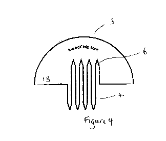
FIG. 4 is a top view perspective of a second embodiment of the multi-purpose
eating
utensil in accordance with the present invention showing an embodiment with
one segment
separated.
FIG. 5 is a top view perspective of a third embodiment of the multi-purpose
eating
utensil in accordance with the present invention showing an embodiment with
two segments
joined to each other.
FIG. 6 is a top view perspective of a third embodiment of the multi-purpose
eating
utensil in accordance with the present invention showing an embodiment with
two segments
separated apart.
CA 02797793 2012-10-26
-6-
FIG. 7 is a top view perspective of a fourth embodiment of the multi-purpose
eating
utensil in accordance with the present invention showing an embodiment where
the device is
used for a non-eating purpose as a paper clip.
FIG. 8 is a top view perspective of a fifth embodiment of the multi-purpose
eating
utensil of the present invention showing an embodiment where the device is
used for a non-
eating purpose.
It is noted that the drawings are intended to depict only typical or exemplary
embodiments of the invention and this many not be necessarily to scale.
Accordingly, the
drawings should not be considered as limiting the scope of the invention. The
invention will
now be described in greater detail with reference to the accompanying
drawings.
DETAILED DESCRIPTION OF THE PREFERRED INVENTION
AND PREFERRED EMBODIMENTS
The figures are referred to herein to describe certain exemplary embodiments
of the
invention. FIG. 1, FIG. 3 and FIG. 5 illustrate, in a top perspective view, a
first and second
embodiment of the multi-purpose eating utensil assembly 10 of the present
invention. In these
first and second embodiments, the assembly is planar or nearly planar and is
heart-shaped 11
or circular 12 with two segments 13 and 14 that are joined or intact and made
separable as
described herein. The eating utensil assemblies 10 and 11 of the first and
second
embodiments comprise two fork implements and that are formed having first food
engagement members 6 or tines 6 for the first fork implement and second food
engagement
members 6 or tines 6 for the second fork implement. As described herein, the
eating utensil
assembly of the invention can accommodate any combination of food engagement
members,
such as a fork, spoon, knife or pick. As exemplified in FIG. 1, FIG. 3 and
FIG. 5, when the
device is in its single unit or intact configuration 11 and 12 so that the
segments 13 and 14 are
joined or otherwise not completely separated, the food engagement members 5 or
tines 5 of
the first fork implement or segment 13 are made to fit together and complement
or interlock
the food engagement members 6 or tines 6 of the second fork implement or
segment 14. The
segments 13 and 14 are separable as described herein along a line of weakness
or weakened
boundary 7 between the two segments 13 and 14 that can be unjoined or
separated upon the
application of pressure, while keeping the integrity of the food engagement
members 6 or
tines 6 intact.
CA 02797793 2012-10-26
-7-
When the segments are separated, as is exemplified in FIG. 2, FIG. 4 or FIG.
6, each
segment can become its own eating utensil with at least one food engagement
member 6. In
some embodiments only one segment 13 or 14 is capable of being used as an
eating utensil
because the second or other segments do not comprise food engagement members.
In the
separated or unjoined segments 13 and 14 of the first or second embodiments
that are
exemplified in FIG. 2, FIG. 4 or FIG. 6, the tines or eating utensil food
engagement members
6 of the fork implements can be easily appreciated. The eating utensil segment
has a region
opposite the fork tines or eating utensil food engagement members 6 that can
be used as a
handle 3 for manipulation of the eating utensil by the user. As described
herein, the eating
utensil can accommodate other food engagement implements or members. For
example, in
the segments 13 and 14 of the first and second embodiments as shown in FIG. 2,
FIG. 4 or
FIG. 6, the eating utensil of the invention can also have a knife member 5 on
one or each of
the segments. As shown in FIG. 2, FIG. 4 or FIG. 6, the knife member 5 can be
serrated, but
other embodiments of the knife member can also be unserrated or in the form of
blade. The
knife engagement member 5 can be disposed laterally on each segment 13 or 14.
Upon
separation, the user can employ the fork implement 4 or 6 of the first segment
13 along with a
knife implement 5 of a second segment as desired 14. Alternatively, the user
can employ one
segment of one assembly for a particular purpose while also employment another
segment
from another assembly for a particular purpose. Any combination is
contemplated by the
invention. The handle 3 members further include a region 15 that can be used
to place desired
text, imagery or other branding devices. If the knife food engagement member 5
of the
implement or eating utensil is employed by the user, a region opposite the
knife food
engagement member can be used as a handle or to otherwise manipulate the
eating utensil.
The device of the invention preferably includes at least one food engagement
member. In one embodiment, the device of the invention includes at least two
eating utensils
or food engagement members. The eating utensils or food engagement members may
be in
the form of forks, spoons, knives, picks or other objects that facilitate food
consumption and
selection and any combination thereof. In one embodiment, the eating utensils
are at least two
forks or at least two spoons or at least two knives and any combination
thereof. In another
embodiment, the eating utensils are at least two forks and at least one knife.
In another
embodiment of the invention, the eating utensils are at least two forks and at
least two knives.
In another embodiment of the invention, the eating utensils are at least one
fork and at least
one knife. In yet another embodiment of the invention, the eating utensils are
at least two
forks and at least two knives and at least two spoons.
CA 02797793 2012-10-26
-8-
The tines of the fork members are formed from resilient materials as described
herein
and the device has a flat or nearly flat cross section, thus presenting a
planar or nearly planar
surface. The multi-purpose device assembly of the invention comprises at least
one segment
or food engagement member, or at least two segments or food engagement
members, or at
least three segments or food engagement members, or at least four segments or
food
engagement members, or at least five segments or food engagement members, or
at least six
segments or food engagement members, or at least seven segments or food
engagement
members, or at least eight segments or food engagement members, or at least
nine segments
or food engagement members, or at least ten segments or food engagement
members.
The segments or food engagement members can be fused or joined together so
that
the segments or food engagement members form a single piece, article or
structure. The
junction between the fused or joined segments or food engagement members can
be
weakened or made susceptible to separation by pressure so that the segments or
food
engagement members can be easily unjoined or separated from each other without
damaging
the functionality of the eating utensils or other non-eating functions of the
device as described
herein. One of skill in the art would be familiar with any of a number of
methods known in
the art to render the junction between the joined or fused segments or food
engagement
members weak or susceptible to separation, including employing a perforated
junction or
other line of weakness bordering each segment, or a boundary bordering each
segment that is
thinned or made weaker by cutting, laser engraving, moulding and the like.
Each segment or food engagement members of the eating utensil assembly can
accommodate at least one form, or at least two forms, or at least three forms,
or at least four
forms, or at least five forms, or at least six forms of eating utensils. Such
forms of eating
utensils that can be part of each segment or food engagement members can be a
knife, fork,
pick or spoon or any combination or hybrid thereof. In one embodiment, there
is at least one
segment or food engagement members to the eating utensil assembly of the
invention with at
least one eating utensil therein, such as a knife, fork, spoon or pick or any
hybrid thereof. In
another embodiment of the invention, there is at least one segment or food
engagement
members to the cutlery of the invention and at least two eating utensils
therein, such as a fork
and a knife, or a fork and a spoon, or a spoon and a knife, or any other
combination or hybrid
thereof. In another embodiment of the invention, there is at least one segment
or food
engagement member in the eating utensil assembly of the invention with at
least three food
engagement members therein, such as a fork, knife and spoon or any other
combination or
hybrid thereof. In yet another embodiment of the invention, there are at least
two segments or
CA 02797793 2012-10-26
-9-
food engagement members in the eating utensil assembly of the invention and at
least two or
at least three food engagement members therein, such as a fork, knife or a
spoon or any
combination or hybrid thereof.
The invention is also capable of being used for non-eating purposes. In one
embodiment of the invention, the non-eating purpose of the invention is as a
clip. By way of
example, FIG. 7 and FIG. 8 illustrate how the multi-purpose device of the
invention can be
used in a non-eating embodiment. All of the same features that apply to the
eating utensil
function as described herein are featured for the non-eating purpose
embodiments except that
the tines 4 or 6 serve to function as a clip member, also now 4 or 6 in this
embodiment. In
order to function as a clip, the user will not separate the segments 13 or 14
at junction 7, but
will keep them intact to some extent. This will allow the tine or clip member
4 or 6 that is
part of the first segment 13 to serve as the front or top part of the clip
while the second
segment 14 will function as the bottom or back part of the clip, with the
paper or other
material in between. In another embodiment of the invention, the device is
used as a clip for
holding various items together, such as a paper bag. Any purpose for which a
clip may be
used is intended. In another embodiment, the clip is a paper clip that holds
sheets of paper
together. In another embodiment, the clip is a paper clip that holds sheets of
paper to another
surface, such as a folder, or a metal surface, or clothing. In another
embodiment of the
invention, the clip holds materials other than paper together, such as
synthetic or non-
synthetic materials. The clip member is formed from the tines of the fork
member, as
described above, and thus present a planar surface that can be used as a clip
for paper or other
materials or items. Because the device of the invention has multiple segments,
as described
herein, the device is capable of being used as multiple clips, depending on
the number of fork
members present in a particular embodiment. In one embodiment, the device has
at least one
fork member and therefore can be used as a single clip. In another embodiment,
the device
has at least two fork members and therefore can be used as two clips. In
another embodiment,
the device has at least three fork members and therefore can be used as three
clips. In another
embodiment of the invention, the device has at least four fork members, and
therefore can be
used as four clips. In yet another embodiment of the invention, the device has
at least five
fork members, and therefore can be used as five clips.
By rendering the eating utensil susceptible to multiple purposes, the device
can serve
dual functions for the same user or transaction. For example, a merchant
selling goods, such
as a food establishment or market, can use the device of the invention to
advertise its services
or to clip receipts, menus, paper or the like to bags or other delivery goods,
while the user can
CA 02797793 2012-10-26
-10-
employ the same device as an eating utensil upon receipt of the goods and
according to the
disclosure herein.
The present invention can be manufactured from any suitable material. By way
of
example, the material can include plastic, wood, paper, biodegradable
cornstarch, or an
edible, biodegradable or oxo-biodegradable material. One of skill in the art
would be familiar
with the type of material that is suitable for use in the present invention
including a wide-
range of natural or synthetic or semi-synthetic materials, including inorganic
or organic solids
or other materials that are used in the manufacture of industrial products. In
one embodiment,
the material is made from a natural substance, such as wood or other suitable
plant material,
for example plywood or rubber. In another embodiment, the material is a
plastic or other
polymer of low or high molecular mass that may also contain other substances
that enhance
the performance of the material. For example, the synthetic material can
include bakelite,
nylon, synthetic rubber, polyethylene, polystyrene, polyvinyl chloride,
polytetrafluoroethylene, or polypropylene. In another embodiment, the device
is made from
magnetic materials that can be attached to the appropriate surfaces.
The shape of the device of the invention can vary to accommodate different
purposes,
needs or desires. The shape of the inventive device can be one with no sides
or with any
number of sizes, such as one, or at least two, or at least three, or at least
four, or at least five,
or at least six, or at least seven, or at least eight, or at least nine, or at
least ten, or at least
eleven, or at least twelve, or at least thirteen, or at least fourteen, or at
least fifteen, or at least
sixteen. By way of example, the shape of the invention can be of any non-
geometric or any
geometric shape, such as an oval, an ellipse, a square, a rhombus, a diamond,
a triangle, a
rectangle, a cylinder, a trapezoid, a pentagon, a hexagon, a septagon, an
octagon, a nonagon,
a concave polygon, a constructible polygon, a kite, a convex polygon, a cyclic
polygon, a
equiangular polygon, a equilateral polygon, a regular polygon, a polydrafter,
a balbis, a
henagon, or digon. By way of example, non-geometric shapes comprise a heart or
any other
part of the anatomy of a living organism, a dog or any other animal, any
animate or any
inanimate object such as a tree or a car or other vehicle, or any celestial
object, or any
trademark or logo or any other sign used to identify a person or business
entity.
The size and dimensions of the device of the invention can vary to accommodate
different purposes for needs. In one embodiment, the invention has a length,
width, radius or
other comparable measurement across any two points of at least 0.5 centimeter,
or at least 0.6
centimeter, or at least 0.7 centimeter, or at least 0.8 centimeter, or at
least 0.9 centimeter, or at
least 1.0 centimeter, or at least 1.1 to 1.5 centimeters, or at least 1 .6 to
2.0 centimeters, or at
CA 02797793 2012-10-26
-11-
least 2.1 to 3.0 centimeters, or at least 3.1 to 4.0 centimeters, or at least
4.1 to 5.0 centimeters,
or at least 5.1 to 6.0 centimeters, or at least 6.1 to 7.0 centimeters, or at
least 7.1 to 8.0
centimeters, or at least 8.1 to 9.0 centimeters, or at least 9.1 to 10.0
centimeters, or at least
10.1 to 11.0 centimeters, or at least 11.1 to 12.0 centimeters, or at least
12.1 to 13.0
centimeters, or at least 13.1 to 14.0 centimeters, or at least 14.1 to 15.0
centimeters, or at least
15.1 to 16.0 centimeters, or at least 16.1 to 17.0 centimeters, or at least
18.0 to 20.0
centimeters. In one embodiment the material has a thickness of at least 0.1
millimeter, or at
least 0.2 millimeter, or at least 0.3 millimeter, or at least 0.4 millimeter,
or at least 0.5
millimeter, or at least 0.6 millimeter, or at least 0.7 millimeter, or at
least 0.8 millimeter, or at
least 0.9 millimeter, or at least 1.0 millimeter, or at least L I to 1.5
millimeters, or at least 1.6
to 2.0 millimeters, or at least 2.1 to 2.5 millimeters, or at least 2.6 to 3.0
millimeters, or at
least 3.1 to 5.0 millimeters, or at least 5.1 to 10.0 millimeters, or at least
10.1 to 15.0
millimeters, or at least 15.1 to 20.0 millimeters, or at least 20.1 to 25.0
millimeters.