Note : Les descriptions sont présentées dans la langue officielle dans laquelle elles ont été soumises.
CA 02798384 2012-11-02
WO 2011/140339 PCT/US2011/035359
AN APPARATUS TO SUBSTANTIALLY MINIMIZE
ACCIDENTAL TIPPING OF A CONTAINER
PARTIALLY FILLED WITH A LIQUID
CROSS REFERENCED TO RELATED APPLICATION
This application is related to U.S. Provisional Patent
Application Serial Number 61/331,606 filed May 5, 2010.
FIELD OF THE INVENTION
The present invention relates, in general, to a container
for holding pre-selected liquids and, more particularly, this
invention relates to an apparatus to substantially minimize
accidental tipping of the container when it is at least
partially filled with a liquid.
BACKGROUND OF THE INVENTION
Prior to the conception and development of the instant
invention, as is generally well known in the prior art, the
accidental tipping of a container filled with a liquid is a
relatively frequent occurrence. This is particularly the case
with small children and the elderly.
Holders to prevent the tipping of containers that are
known to applicant and are presently available on the market
are generally permanently connected to or disposed within a
device such as an automobile. Such holders are further
designed to hold only drink containers. It is believed that
it would be desirable to have a holder to prevent the tipping
of containers that is portable and, in addition to holding
drink containers, offer designs that hold containers other
than a drink container.
1
CA 02798384 2012-11-02
WO 2011/140339 PCT/US2011/035359
One such design was taught in my prior patent
applications bearing Serial Numbers 10/437,817 and 10/613,243,
filed on May 14, 2003, and July 03, 2003, respectively. The
problem with these designs is that the container must be
twisted in order to either insert it into the holder and/or to
remove it from the holder.
No prior art inventions which applicant is currently
aware of offer the anti-tipping ability while lifting the
container straight up to remove it from the holder and placing
the container back into the holder without having to twist it.
BRIEF SUMMARY OF THE INVENTION
The present invention provides an apparatus to
substantially minimize accidental tipping of a container at
least partially filled with a preselected liquid. The
apparatus includes a first portion engageable with at least
one of a tray, a coaster, a cup holder disposed in a vehicle
and the container. The first portion includes a generally
round hollow member that has each of a first predetermined
width, an outer surface having a first predetermined diameter
and an inner surface having a second predetermined diameter.
The first portion further includes a first predetermined
plurality of gear like teeth, having a predetermined pitch,
formed at least one of in and on the inner surface of said
generally round hollow member. There is an annular member
disposed on and extending outwardly from the outer surface of
the generally round hollow member at a predetermined location.
2
CA 02798384 2012-11-02
WO 2011/140339 PCT/US2011/035359
Such annular member is preferably generally rectangular in
cross section. Additionally, the first portion includes a
first means having at least a portion of an upper surface
thereof disposed below and engageable with a bottom surface of
the annular member for each of providing assistance in
retaining the generally round hollow member in place and
enabling such generally round hollow member to rotate
thereover. A second means having at least a portion of a
bottom surface thereof disposed above and facing an upper
surface of said annular member is provided for providing
assistance in retaining the generally round hollow member in
place. The final essential element of the first portion of
the apparatus is a third means engageable with each of the
first means and the second means for maintaining a
predetermined distance between the at least a portion of such
upper surface of the first means and the at least a portion of
the bottom surface of such second means. The final essential
element of the apparatus is a second portion disposed one of
in and on one of the tray, coaster and cup holder when the
first portion is disposed on such container and on the
container when such first portion is disposed one of in and on
the one of such tray, coaster and cup holder. The second
portion has a second predetermined plurality of gear like
teeth disposed on a generally round member disposed on an
outer surface thereof and having a predetermined pitch for
3
CA 02798384 2012-11-02
WO 2011/140339 PCT/US2011/035359
mating engagement with the first predetermined plurality of
teeth.
OBJECTS OF THE INVENTION
It is, therefore, one of the primary objects of the
present invention to provide an apparatus that is useful as
either a portable or a stationary holding device and which
will substantially minimize the accidental tipping of a
container at least partially filled with a liquid.
Another object of the present invention is to provide an
apparatus which substantially minimizes tipping of a container
that includes a means for one of releasably and permanently
securing the apparatus to a pre-selected smooth surface.
Still another object of the present invention is to
provide an apparatus which substantially minimizes tipping of
a container that is relatively easy to use.
Yet another object of the present invention is to provide
an apparatus which substantially minimizes tipping of a
container that is relatively inexpensive to manufacture.
A further object of the present invention is to provide
an apparatus which substantially minimizes tipping of a
container that can be used in a variety of applications, such
as, a lap top tray, a cafeteria type tray, a coaster, a cup
holder disposed in a vehicle and a tray attached to a ladder.
An additional object of the present invention is to
provide an apparatus which substantially minimizes tipping of
4
CA 02798384 2012-11-02
WO 2011/140339 PCT/US2011/035359
a container that does not require twisting the container to
remove it from the apparatus.
Still yet another object of the present invention is to
provide an apparatus which substantially minimizes tipping of
a container incorporated into a lap top tray having one of a
pre-selected image disposed on the upper surface of the tray.
It is a still further object of the present invention to
provide an apparatus which substantially minimizes tipping of
a container that can be retrofitted for a variety of
applications.
In addition to the several objects and advantages of the
instant invention which have been specifically described in
detail above, it should be noted that various other objects and
advantages of the present invention will become more readily
apparent to persons who are skilled in the same and related arts
from the following more detailed description of the invention,
particularly, when such description is taken in conjunction
with the attached drawing figures and the appended claims.
BRIEF DESCRIPTION OF THE DRAWINGS
Figure 1 is a cross sectional view of one of the
presently preferred embodiments of the invention for use with
a tray;
Figure 2A is a side elevation view of a container
equipped with an alternative embodiment of a portion of an
external gear assembly attached thereto;
5
CA 02798384 2012-11-02
WO 2011/140339 PCT/US2011/035359
Figure 2B is a side elevation view of a gear for
attachment to the container illustrated in Figure 2A;
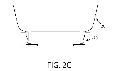
Figure 2C is a side elevation view of the container
illustrated in Figure 2A having the gear illustrated in Figure
2B attached thereto;
Figure 3 is a side view of a coaster equipped with a
presently preferred embodiment of the present invention;
Figures 4A-D are views illustrating a presently preferred
embodiment of the apparatus as it will be used in a vehicle
cup holder (not shown);
Figures 5A-C are views illustrating a container swivel
type receiver assembly;
Figures 6A-B are views illustrating a permanent type
swivel assembly which can be used on cafeteria style trays as
well as airline drop down trays;
Figures 7A-B are views illustrating an alternative
embodiment of an apparatus for use in a cup holder of an
automobile;
Figures 8A-B are views illustrating another alternative
embodiment of the invention having a snap lock connection for
use with a tray;
Figure 9 is a view illustrating a permanent swiveling
gear like assembly which can be mounted to either a container
or another surface;
6
CA 02798384 2012-11-02
WO 2011/140339 PCT/US2011/035359
Figure 10 is a view illustrating a permanent non-
swiveling gear like assembly which can be mounted to either a
container or another surface;
Figures 11-14 illustrate a number of alternative
embodiments of the invention having a mobile swiveling gear
like assembly; and
Figures 15A-C illustrate an embodiment of the invention
for connection to a paper cup.
BRIEF DESCRIPTION OF THE PRESENTLY
PREFERRED AND VARIOUS ALTERNATIVE
EMBODIMENTS OF THE INVENTION
Prior to proceeding to the more detailed description of
the present invention, it should be noted that identical
components having identical functions have been identified
with identical reference numerals throughout the several views
illustrated in the attached drawing figures.
Now reference is made more particularly to drawing
Figures 1, 2A-C and 3. Illustrated therein are two of the
presently preferred embodiments of an apparatus, generally
designated 10, which will substantially minimize accidental
tipping of a container (Figs 2A and 2C), generally
designated 20, which is at least partially filled with a
liquid.
The apparatus 10 comprises a first portion, generally
designated 30, engageable with at least one of a tray 12, a
coaster 14, a cup holder (not shown) disposed in a vehicle
(not shown) and the container 20. The first portion 30
7
CA 02798384 2012-11-02
WO 2011/140339 PCT/US2011/035359
includes a generally round hollow member 18 having each of a
first predetermined width (W), an outer surface 22 having a
first predetermined diameter (Dl) and an inner surface 24
having a second predetermined diameter (D2).
The first portion 30 further includes a first
predetermined plurality of gear like teeth 26, having a
predetermined pitch, formed at least one of in and on the
inner surface 24 of the generally round hollow member 18.
There is an annular member 28 disposed on and extending
outwardly from the outer surface 22 of the generally round
hollow member 18 at a predetermined location. The annular
member 28, in one presently preferred embodiment, has a
generally rectangular cross section and is located about
midway between the width W of the generally hollow member 18,
although it could be positioned closely adjacent one edge
thereof.
The first portion 30 further includes a first means,
generally designated 40, having at least a portion of an upper
surface 32 thereof disposed below and engageable with a bottom
surface 34 of the annular member 28 for each of providing
assistance in retaining the generally round hollow member 18
in place and enabling such generally round hollow member 18 to
rotate thereover. A second means, generally designated 50, is
also provided. Second means 50 has at least a portion of a
bottom surface 36 thereof disposed above and facing an upper
surface 38 of the annular member 28 for providing assistance
8
CA 02798384 2012-11-02
WO 2011/140339 PCT/US2011/035359
in retaining the generally round hollow member 18 in place.
The final essential component of the first portion 30 of
apparatus 10 is a third means, generally designated 60, for
engaging with each of the first means 40 and the second
means 50 for maintaining a predetermined distance between the
at least a portion of the upper surface 32 of such first
means 40 and the at least a portion of the bottom surface 36
of such second means 50. Preferably third means 60 is a
friction fit.
The final essential element of the apparatus 10 is a
second portion, generally designated 70, disposed one of in
and on one of the tray 12, coaster 14 and cup holder 16 when
the first portion 30 is disposed on the container 20 and on
such container 20 when the first portion 30 is disposed one of
in and on such one of such tray 12, coaster 14 and cup
holder 16. The second portion 70 has a second predetermined
plurality of gear like teeth 42 disposed on a generally round
member 44 disposed on an outer surface 46 thereof and having a
predetermined pitch for mating engagement with the first
predetermined plurality of teeth 26. Preferably, the second
portion 70 will be disposed on the container 20.
Reference is now made to Figures 4A-D. Illustrated
therein is an alternative embodiment of the first portion 30
of apparatus 10 as it would be used in a vehicle cup holder
(not shown). In this embodiment second means 50 includes
finger like member 48 engageable with a permanent base 52.
9
CA 02798384 2012-11-02
WO 2011/140339 PCT/US2011/035359
Base 52 has an adhesive surface 54 disposed on the bottom
surface thereof for adhering base 52 to the bottom of the
vehicle cup holder.
Figures 5A-C are views illustrating a container 20 swivel
type receiver assembly 50 for gear like member 18.
Figures 6A-B are views illustrating a permanent type
swivel assembly 50 which can be used on cafeteria style trays
(not shown) as well as airline drop down trays (not shown).
Figures 7A-B are views illustrating an alternative
embodiment of an apparatus for use in a cup holder of an
automobile. In this embodiment a series of magnets 58 are
adhered to the bottom of the receiver assembly 50 for
attraction to a metal plate 56 adhered to the bottom of the
vehicle cup holder.
Figures 8A-B are views illustrating another alternative
embodiment of the invention having a snap lock connection,
generally designated 80, for use with a tray (not shown)
having an aperture formed there through.
Figure 9 is a view illustrating a permanent swiveling
gear like assembly 18 which can be mounted to either a
container 20 or other surface and Figure 10 is a view
illustrating a permanent non-swiveling gear like assembly 18
which can be mounted to either a container 18 or other
surface.
Figures 11-14 illustrate a number of alternative
embodiments of the invention having a mobile swiveling gear
CA 02798384 2012-11-02
WO 2011/140339 PCT/US2011/035359
like assembly 18 being held against a surface using a suction
type member 62.
Figures 15A-C illustrate two embodiments of the invention
for connection to a paper cup. In the embodiment shown in
Figure 16A there is illustrated a mechanism, generally
designated 90, that snaps both open and closed to engage the
inside of the bottom rim 64 of paper cup 66. In the embodiment
shown in Figure 16B there is illustrated a mechanism,
generally designated 100, that is normally closed and snaps
open to engage the inside of the bottom rim 64 of paper
cup 66.
In each of the embodiments taught herein the container is
selected from a group consisting of a glass, formed from
either glass or plastic, a plastic cup, a paper cup and a
metal container.
The first predetermined width of the generally round
hollow member, in the presently preferred embodiment of the
invention, will normally be between about 0.125 inch and
about 1.00 inch.
Additionally, the first predetermined plurality of teeth
are formed on the inner surface of such generally round hollow
member and the predetermined location of the annular member
disposed on the outer surface of such generally round hollow
member is one of closely adjacent a predetermined edge of the
generally round hollow member and about midway between the
outer edges thereof. In the presently preferred embodiment of
11
CA 02798384 2012-11-02
WO 2011/140339 PCT/US2011/035359
the invention, the predetermined location of such annular
member is about midway between such outer edges of the
generally hollow round member.
The first means is a ledge member which can be formed on
a separate piece or as a part of a bore formed in a tray. It
would be less costly when the first portion is a tray and the
ledge is one of formed as a landing on such tray.
In one presently preferred embodiment of the invention
the third means is one of a friction fit and a predetermined
plurality of fingers. Further, the first and second
predetermined plurality of teeth are identical.
When the first portion is a cup holder disposed in a
vehicle and then the apparatus further includes a fourth means
having at least a portion thereof disposed on a bottom surface
thereof. Such fourth means is selected from an adhesive,
preferably a double sided adhesive, and at least one magnet.
While both a presently preferred and several alternative
embodiments of the invention have been described in detail
above it should be understood that various other arrangements
of the components taught herein can be envisioned by those
persons skilled in the art without departing from the spirit
and scope of the appended claims.
12