Sélection de la langue

Search

Sommaire du brevet 2798397 

Énoncé de désistement de responsabilité concernant l'information provenant de tiers

Une partie des informations de ce site Web a été fournie par des sources externes. Le gouvernement du Canada n'assume aucune responsabilité concernant la précision, l'actualité ou la fiabilité des informations fournies par les sources externes. Les utilisateurs qui désirent employer cette information devraient consulter directement la source des informations. Le contenu fourni par les sources externes n'est pas assujetti aux exigences sur les langues officielles, la protection des renseignements personnels et l'accessibilité.

Disponibilité de l'Abrégé et des Revendications

L'apparition de différences dans le texte et l'image des Revendications et de l'Abrégé dépend du moment auquel le document est publié. Les textes des Revendications et de l'Abrégé sont affichés :

  • lorsque la demande peut être examinée par le public;
  • lorsque le brevet est émis (délivrance).
(12) Brevet: (11) CA 2798397
(54) Titre français: ENSEMBLE DE LEVEE DE MODULE REGLABLE
(54) Titre anglais: ADJUSTABLE MODULE LIFT ASSEMBLY
Statut: Accordé et délivré
Données bibliographiques
(51) Classification internationale des brevets (CIB):
  • B66C 01/16 (2006.01)
(72) Inventeurs :
  • HERMANN, ULRICH (RICK) (Canada)
  • OLEARCZYK, JACEK (Canada)
(73) Titulaires :
  • PCL INDUSTRIAL MANAGEMENT INC.
(71) Demandeurs :
  • PCL INDUSTRIAL MANAGEMENT INC. (Canada)
(74) Agent: BENNETT JONES LLP
(74) Co-agent:
(45) Délivré: 2017-03-07
(22) Date de dépôt: 2012-12-10
(41) Mise à la disponibilité du public: 2014-03-21
Requête d'examen: 2016-07-06
Licence disponible: S.O.
Cédé au domaine public: S.O.
(25) Langue des documents déposés: Anglais

Traité de coopération en matière de brevets (PCT): Non

(30) Données de priorité de la demande:
Numéro de la demande Pays / territoire Date
61/704,219 (Etats-Unis d'Amérique) 2012-09-21

Abrégés

Abrégé français

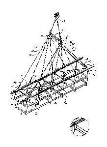
Un ensemble de levage de module comprend des première et seconde plaques dadaptateur multipoint séparées par une barre de répartition transversale horizontale; un bâti de levage ayant des première et seconde poutres de levage longitudinales séparées par un étançonnement transversal horizontal; une pluralité délingues de longueur réglable reliant la première plaque dadaptateur multipoint à la première poutre de levage et reliant la seconde plaque dadaptateur multipoint à la seconde poutre de levage; et une pluralité densembles délément de coulissement fixés chacun de façon à pouvoir coulisser aux première et seconde poutres de levage, et une manille de levage pour la fixation à un module.


Abrégé anglais

A module lift assembly includes first and second multipoint adapter plates separated by a horizontal transverse spreader bar; a lift frame having first and second longitudinal lift beams separated by horizontal transverse bracing; a plurality of slings of adjustable length connecting the first multipoint adapter plate to the first lift beam and connecting the second multipoint adapter plate to the second lift beam; and a plurality of slider assemblies each slidingly affixed to the first and second lift beams, and a a lift shackle for attaching to a module.

Revendications

Note : Les revendications sont présentées dans la langue officielle dans laquelle elles ont été soumises.


WHAT IS CLAIMED IS:
1. A module lift assembly comprising:
(a) a lift assembly comprising a first and second multipoint adapter plates
separated
by a horizontal transverse spreader bar;
(b) a lift frame comprising first and second longitudinal lift beams
separated by
horizontal transverse bracing;
(c) a first plurality of slings connecting the first multipoint adapter
plate to the first
lift beam and a second plurality of slings connecting the second multipoint
adapter plate
to the second lift beam, wherein each sling comprises a member of adjustable
length;
and
(d) a first plurality of slider assemblies and a second plurality of slider
assemblies,
each having a first end slidingly affixed to the first or second lift beams
respectively,
and a second end comprising a lift shackle for attaching to a module.
2. The assembly of claim 1 wherein each sling adjustable length member
comprises a
telescoping rod or flat bar and tube or rectangular shell assembly.
3. The assembly of claim 2 wherein each sling further comprises a turnbuckle
for secondary
length adjustment.
4. The assembly of claim 1 wherein each multipoint adapter plate comprises a
pair of
spaced apart plates, and having an apex for attachment to the transverse
spreader bar, and
8

a plurality of attachment points for the first or second plurality of slings,
arrayed on an
arc opposite the apex.
5. The assembly of claim 1 wherein the first plurality of slider assemblies
along the first lift
beam are interconnected and the second plurality of slider assemblies along
the second
lift beam are interconnected.
6. The assembly of claim 1 wherein the horizontal transverse spreader bar
comprises a lift
ear disposed at each end of the transverse spreader bar, wherein each lift ear
comprises a
pivoting attachment to a crane hook, and a pivoting attachment to a shackle
from which a
different one of the multipoint adapter plates is suspended, wherein the
pivoting
attachments permit pivoting movement of the horizontal transverse spreader bar
relative
to the crane hook and the multipoint adapter plates about a horizontal axis,
parallel to the
lift beams.
7. The assembly of claim 6 wherein each lift ear comprises a single pivot pin
as the pivoting
attachment to both the crane hook and the shackle from which the different one
of the
multipoint adapter plates is suspended.
8. The assembly of claim 1 wherein the first lift beam comprises an upper
flange and a
lower flange, wherein each of the first plurality of slings is attached to the
upper flange of
the first lift beam, and wherein each of the first plurality of slider
assemblies is supported
by the lower flange of the first lift beam.
9. The assembly of claim 8 wherein the first lift beam comprises an I-beam or
a double web
beam.
9

10. A module lift assembly comprising:
(a) an upper lift assembly;
(b) a lift frame comprising first and second longitudinal lift beams
separated by
horizontal transverse bracing;
(c) a first plurality of slings connecting the upper lift assembly to the
first lift beam and
a second plurality of slings connecting the upper lift assembly to the second
lift
beam, wherein each sling comprises a member of adjustable length; and
(d) a first plurality of slider assemblies, each having a first end
slidingly affixed to the
first lift beam, and a second end comprising a lift shackle for attaching to a
module,
and a second plurality of slider assemblies, each having a first end slidingly
affixed
to the second lift beam, and a second end comprising a lift shackle for
attaching to
the module.
11. The assembly of claim 10 wherein each sling adjustable length member
comprises a
telescoping rod or flat bar and tube or rectangular shell assembly.
12. The assembly of claim 11 wherein each sling further comprises a turnbuckle
for
secondary length adjustment.
13. The assembly of claim 10 wherein either or both the first or second
plurality of slider
assemblies are interconnected,
14. The assembly of claim 10 wherein the upper lift assembly comprises a
horizontal
spreader bar separating first and second multipoint adapter plates, to which
the first and
second plurality of slings are attached, respectively.

15. The assembly of claim 14 wherein the horizontal transverse spreader bar
comprises a lift
ear disposed at each end of the transverse spreader bar, wherein each lift ear
comprises a
pivoting attachment to a crane hook, and a pivoting attachment to a shackle
from which a
different one of the multipoint adapter plates is suspended, wherein the
pivoting
attachments permit pivoting movement of the horizontal transverse spreader bar
relative
to the crane hook and the multipoint adapter plates about a horizontal axis,
parallel to the
lift beams.
16. The assembly of claim 15 wherein each lift ear comprises a single pivot
pin as the
pivoting attachment to both the crane hook and the shackle from which the
different one
of the multipoint adapter plates is suspended.
17. The assembly of claim 10 wherein each lift beam comprises an upper flange
and a lower
flange, wherein each of the first and second plurality of slings is attached
to the upper
flange of either the first or second lift beams, and wherein each of the first
or second
plurality of slider assemblies is supported by the lower flange of either the
first or second
lift beam.
18. The assembly of claim 17 wherein either lift beam comprises an I-beam or a
double web
beam.
19. The assembly of claim 14 wherein each multipoint adapter plate comprises a
pair of
spaced apart plates, and having an apex for attachment to the transverse
spreader bar, and
a plurality of attachment points for the first or second plurality of slings,
arrayed on an
arc opposite the apex.
11

20. The assembly of claim 19 wherein each multipoint adapter plate further
comprises a
plurality of pins or bolts separating the pair of spaced apart plates and
forming the
plurality of attachment points for the first or second plurality of slings,
21. A method of lifting a module having a centre-of-gravity (COG) using a
module lift
assembly having two longitudinal, transversely spaced apart lift beams,
comprising the
steps of:
(a) attaching the module to the lift beams using slider assemblies attached
to the lift
beams;
(b) sliding the slider assemblies in the longitudinal direction until the
module COG is
centered longitudinally under the lift assembly; and
(c) adjusting the relative vertical position of the lift beams until the
module COG is
centered transversely under the lift assembly.
22. The method of claim 21 wherein the slider assemblies are interconnected,
such that all
the slider assemblies along one lift beam may be moved in unison.
23. The method of claim 21 or 22 wherein the slider assemblies may slide along
the length of
the lift beam without physical obstruction.
24. The method of claim 21, 22 or 23, wherein each slider assembly slides
along a lower
flange of a lift beam.
12

Description

Note : Les descriptions sont présentées dans la langue officielle dans laquelle elles ont été soumises.


CA 02798397 2012-12-10
ADJUSTABLE MODULE LIFT ASSEMBLY
Field of the Invention
The present invention is directed to a module lift frame which is conveniently
adjustable
to accommodate modules with a variable number of lift points, range of module
lengths and
widths, and off-centre centre of gravity.
Background
Heavy industrial plants, particularly in the bitumen, heavy oil and
petrochemical industries
are increasingly being constructed using pre-fabricated modules. A standard
module
comprises a structural steel frame, and may be 20 feet wide, 80 to 120 feet
long, and up to 24
feet high, with weights ranging from 50 to 160 metric tons,
These modules are lifted and installed using cranes and rigging assemblies
such as that
shown in Figure 1. However, as the centre of gravity of the module may not
coincide with the
physical centre of the module, the rigging must be adjusted so that the module
can be lifted
with substantially tension in the rigging components. The large number of
spreader bars,
slings and shackles introduce a large number of potential pinch points, each
of which carries a
potential injury site. The complexity of the rigging causes lengthy delays
while adjusting for
the module centre of gravity and pick point configurations. The rigging does
not provide any
stiffness to the module causing significant stresses within the module for
unequally loaded
modules.
1

CA 02798397 2012-12-10
Therefore, there is a need in the art for a module lift frame which mitigates
the difficulties
of the prior art.
Summary Of The Invention
In one aspect, the invention may comprise a module lift assembly comprising:
(a) a lift assembly comprising a first and second multipoint adapter plates
separated
by a horizontal transverse spreader bar;
(b) a lift frame comprising first and second longitudinal lift beams separated
by
horizontal transverse bracing;
(c) a plurality of slings connecting the first multipoint adapter plate to
the first lift
beam and connecting the second multipoint adapter plate to the second lift
beam,
wherein each sling comprises a member of adjustable length; and
(d) a plurality of slider assemblies each having a first end slidingly affixed
to the
first and second lift beams, and a second end comprising a lift shackle for
attaching
to a module.
Brief Description Of The Drawings
In the drawings, like elements are assigned like reference numerals. The
drawings are not
necessarily to scale, with the emphasis instead placed upon the principles of
the present
2

CA 02798397 2012-12-10
invention. Additionally, each of the embodiments depicted are but one of a
number of
possible arrangements utilizing the fundamental concepts of the present
invention. The
drawings are briefly described as follows:
[0002] Figure 1 is diagram of a prior art module lift rigging.
[0003] Figure 2 shows one embodiment of a module lift assembly of the present
invention.
[0004] Figure 3 shows a detail of Figure 2, showing one embodiment of a
multipoint adapter
plate.
[0005] Figure 4 shows one embodiment of an adjustable length member for
attachment
between one embodiment of the slings and the lift beam.
[0006] Figure 5 shows one embodiment of a slider assembly.
[0007] Figure 6 shows a side view of the adjustment of the slider assemblies
for a module
having a offset centre of gravity.
[0008] Figure 7 shows an end view of the assembly before adjustment of the
length of the
sling assemblies for a module having an offset centre of gravity.
Detailed Description Of Preferred Embodiments
The invention relates to a module lift assembly. When describing the present
invention,
all terms not defined herein have their common art-recognized meanings. To the
extent that
the following description is of a specific embodiment or a particular use of
the invention, it is
3

CA 02798397 2012-12-10
intended to be illustrative only, and not limiting of the claimed invention.
The following
description is intended to cover all alternatives, modifications and
equivalents that are
included in the spirit and scope of the invention, as defined in the appended
claims.
As shown in Figure 1, a prior art rigging assembly includes spreader bars
orientied in both
the longitudinal and transverse directions. Adjusting the rigging to
accommodate a non-
centred centre of gravity (COG) involves multiple adjustments of various
rigging components.
In one embodiment of the present invention, a module (M) lift assembly of the
present
invention comprises:
(a) an upper lift assembly comprising a first and second multipoint
adapter plates (10,
12) separated by a transverse spreader bar (14);
(b) a lift frame comprising first and second longitudinal lift beams (20, 22)
separated by transverse bracing (24) and diagonal bracing (26);
(c) a plurality of slings (30) connecting the first multipoint adapter plate
(10) to the
first lift beam (20) and connecting the second multipoint adapter plate (12)
to the
second lift beam (22), wherein each sling (30) comprises a member of
adjustable
length (40); and
(d) a plurality of slider assemblies (50) each having a first end (52)
slidingly affixed
to the first and second lift beams (20, 22), and a second end (54) comprising
a lift
shackle (56) for attaching to the module (M) being lifted.
4

CA 02798397 2012-12-10
The upper lift assembly connects to a crane hook (5) which is attached by wire
rope to
either end of the transverse spreader bar (14). First and second multipoint
adapter plates (10,
12) are attached to lift ears (101) disposed at the ends of the transverse
spreader bar (14).
Each multipoint adapter plate (10, 12) comprises a pair of parallel plates
spaced apart with
pins or bolts. Each adapter plate has an apex which accepts and hangs from a
shackle (102)
connected to the lift ear (101). A plurality of sling attachments (103) are
arrayed in an arc
opposite the apex, as may be seen in Figure 3.
The lift frame comprises first and second longitudinal lift beams (20, 22)
separated by
transverse bracing (24) and diagonal bracing (26). In one embodiment, the
longitudinal lift
beams comprise I-beams or double web beams having a lower flange (200). Each
lift beam
may be a single unitary beam or may comprise multiple interconnected lift
beams. The lift
frame is connected to the adapter plates (10, 12) by a plurality of a
plurality of slings (30)
connecting the first multipoint adapter plate (10) to the first lift beam (20)
and connecting the
second multipoint adapter plate (12) to the second lift beam (22). Each length
of sling (30)
may comprise a number of sling segments interconnected with intermediate
shackles (32) and
attached to an upper surface of each lift beam. Preferably, the lift assembly
comprises an even
number of slings, equally distributed between the first and second adapter
plates and lift
beams. Preferably, the slings attach to the lift beams in fixed positions,
spaced in equidistant
manner along the length of the lift beams.
Each sling (30) further comprises at least one member of adjustable length
(40). In a
preferred embodiment, the adjustable length member (40) comprises a
telescoping rod or flat
5

CA 02798397 2012-12-10
bar (42) and tube or rectangular shell (44) arrangement, which may be fixed
with a removable
pin (46) in various positions. Secondary length adjustment may be provided by
a turnbuckle
(48) which may be connected to the sling immediately above or below the
adjustable length
member (40).
Each lower flange of each lift beam (20, 22) supports a plurality of slider
assemblies (50),
which each have a first end (52) slidingly affixed to the first and second
lift beam (20, 22)
lower flanges, and a second end (54) comprising a lift shackle (56). The lift
shackle (56)
provides the connection to the module (M) being lifted.
As is apparent, the number and placing of the slider assemblies is dependent
upon the
module (M) being lifted. In the exemplary embodiment shown in Figure 2, the
module (M)
comprises 6 columns along each longitudinal side, therefore, there are 6
slider assemblies on
each lift beam, each of which connects to column. In one embodiment, the
slider assemblies
on each lift beam are linearly interconnected by means of cables (58) or rods,
so that the slider
assemblies move in unison along the length of the lift beam.
In one embodiment, the lift assembly may comprise a plurality of legs (70)
along the lift
beams (20, 22) upon which the lift assembly may rest upon for storage when the
assembly is
not in use. These legs may be permanently attached in a position which does
not interfere
with the use of the assembly, or may be detachable.
6

CA 02798397 2012-12-10
In the embodiment illustrated in Figure 2, the lift beams (20, 22) are of
unitary construction.
In alternative embodiments, the lift beams may be multi-component spliced
beams, which
may provide the ability to shorten or lengthen the lift beams as necessary or
desired.
In operation, the lift assembly may be adjusted so as to place the COG of the
module (M)
immediately below (vertically aligned) with the centre of the upper lift
assembly, which will
be the midpoint of the spreader bar (14).
In the longitudinal direction, this may be accomplished by moving the sliding
assemblies
along each lift beam until the COG of the module is vertically aligned with
the apex of the
first and second adapter plates, as is shown in Figure 6.
In the transverse direction, this may be accomplished by lengthening or
shortening the
slings along each lift beam. As may be seen in Figure 7, the COG of the module
may be
shifted towards the midpoint of the spreader bar (14) by shortening those
slings attached
between the first adapter plate (10) and the first lift beam (20) and/or
lengthening those slings
attached between the second adapter plate (12) and the second lift beam (22).
As will be apparent to those skilled in the art, various modifications,
adaptations and
variations of the foregoing specific disclosure can be made without departing
from the scope
of the invention claimed herein.
7

Dessin représentatif
Une figure unique qui représente un dessin illustrant l'invention.
États administratifs

2024-08-01 : Dans le cadre de la transition vers les Brevets de nouvelle génération (BNG), la base de données sur les brevets canadiens (BDBC) contient désormais un Historique d'événement plus détaillé, qui reproduit le Journal des événements de notre nouvelle solution interne.

Veuillez noter que les événements débutant par « Inactive : » se réfèrent à des événements qui ne sont plus utilisés dans notre nouvelle solution interne.

Pour une meilleure compréhension de l'état de la demande ou brevet qui figure sur cette page, la rubrique Mise en garde , et les descriptions de Brevet , Historique d'événement , Taxes périodiques et Historique des paiements devraient être consultées.

Historique d'événement

Description Date
Représentant commun nommé 2019-10-30
Exigences relatives à la révocation de la nomination d'un agent - jugée conforme 2017-05-25
Exigences relatives à la nomination d'un agent - jugée conforme 2017-05-25
Demande visant la nomination d'un agent 2017-04-28
Demande visant la révocation de la nomination d'un agent 2017-04-28
Inactive : Correspondance - Transfert 2017-04-28
Accordé par délivrance 2017-03-07
Inactive : Page couverture publiée 2017-03-06
Préoctroi 2017-01-27
Inactive : Taxe finale reçue 2017-01-27
Un avis d'acceptation est envoyé 2016-11-28
Lettre envoyée 2016-11-28
Un avis d'acceptation est envoyé 2016-11-28
Inactive : QS réussi 2016-11-24
Inactive : Approuvée aux fins d'acceptation (AFA) 2016-11-24
Modification reçue - modification volontaire 2016-11-15
Modification reçue - modification volontaire 2016-11-08
Inactive : Dem. de l'examinateur par.30(2) Règles 2016-08-08
Inactive : Rapport - Aucun CQ 2016-08-08
Avancement de l'examen jugé conforme - alinéa 84(1)a) des Règles sur les brevets 2016-07-13
Lettre envoyée 2016-07-13
Inactive : Avancement d'examen (OS) 2016-07-06
Exigences pour une requête d'examen - jugée conforme 2016-07-06
Inactive : Taxe de devanc. d'examen (OS) traitée 2016-07-06
Toutes les exigences pour l'examen - jugée conforme 2016-07-06
Requête d'examen reçue 2016-07-06
Lettre envoyée 2014-10-01
Inactive : Transfert individuel 2014-09-22
Demande publiée (accessible au public) 2014-03-21
Inactive : Page couverture publiée 2014-03-20
Inactive : CIB en 1re position 2013-03-26
Inactive : CIB attribuée 2013-03-26
Inactive : Certificat de dépôt - Sans RE (Anglais) 2012-12-20
Demande reçue - nationale ordinaire 2012-12-20

Historique d'abandonnement

Il n'y a pas d'historique d'abandonnement

Taxes périodiques

Le dernier paiement a été reçu le 2016-10-05

Avis : Si le paiement en totalité n'a pas été reçu au plus tard à la date indiquée, une taxe supplémentaire peut être imposée, soit une des taxes suivantes :

  • taxe de rétablissement ;
  • taxe pour paiement en souffrance ; ou
  • taxe additionnelle pour le renversement d'une péremption réputée.

Les taxes sur les brevets sont ajustées au 1er janvier de chaque année. Les montants ci-dessus sont les montants actuels s'ils sont reçus au plus tard le 31 décembre de l'année en cours.
Veuillez vous référer à la page web des taxes sur les brevets de l'OPIC pour voir tous les montants actuels des taxes.

Titulaires au dossier

Les titulaires actuels et antérieures au dossier sont affichés en ordre alphabétique.

Titulaires actuels au dossier
PCL INDUSTRIAL MANAGEMENT INC.
Titulaires antérieures au dossier
JACEK OLEARCZYK
ULRICH (RICK) HERMANN
Les propriétaires antérieurs qui ne figurent pas dans la liste des « Propriétaires au dossier » apparaîtront dans d'autres documents au dossier.
Documents

Pour visionner les fichiers sélectionnés, entrer le code reCAPTCHA :


Pour visualiser une image, cliquer sur un lien dans la colonne description du document (Temporairement non-disponible). Pour télécharger l'image (les images), cliquer l'une ou plusieurs cases à cocher dans la première colonne et ensuite cliquer sur le bouton "Télécharger sélection en format PDF (archive Zip)" ou le bouton "Télécharger sélection (en un fichier PDF fusionné)".

Liste des documents de brevet publiés et non publiés sur la BDBC .

Si vous avez des difficultés à accéder au contenu, veuillez communiquer avec le Centre de services à la clientèle au 1-866-997-1936, ou envoyer un courriel au Centre de service à la clientèle de l'OPIC.

({010=Tous les documents, 020=Au moment du dépôt, 030=Au moment de la mise à la disponibilité du public, 040=À la délivrance, 050=Examen, 060=Correspondance reçue, 070=Divers, 080=Correspondance envoyée, 090=Paiement})


Description du
Document 
Date
(aaaa-mm-jj) 
Nombre de pages   Taille de l'image (Ko) 
Description 2012-12-09 7 252
Abrégé 2012-12-09 1 16
Revendications 2012-12-09 2 38
Dessin représentatif 2014-01-28 1 7
Revendications 2016-11-07 5 164
Dessins 2016-11-14 7 116
Dessin représentatif 2016-11-20 1 16
Dessin représentatif 2016-11-27 1 17
Dessin représentatif 2017-02-02 1 17
Certificat de dépôt (anglais) 2012-12-19 1 167
Rappel de taxe de maintien due 2014-08-11 1 112
Courtoisie - Certificat d'enregistrement (document(s) connexe(s)) 2014-09-30 1 104
Accusé de réception de la requête d'examen 2016-07-12 1 176
Avis du commissaire - Demande jugée acceptable 2016-11-27 1 161
Taxes 2014-08-14 1 24
Taxes 2015-08-25 1 24
Avancement d'examen (OS) 2016-07-05 2 79
Demande de l'examinateur 2016-08-07 3 167
Modification / réponse à un rapport 2016-11-07 12 323
Modification / réponse à un rapport 2016-11-14 3 88
Taxe finale 2017-01-26 1 27