Note : Les descriptions sont présentées dans la langue officielle dans laquelle elles ont été soumises.
CA 02798606 2012-11-06
WO 2011/146219 PCT/US2011/034468
1
CUTTING DART AND
METHOD OF USING THE CUTTING DART
FIELD OF THE DISCLOSURE
[0001] The present disclosure relates generally to a cutting dart and a
method of cutting
coiled tubing using the cutting dart.
BACKGROUND
[0002] Coiled tubing is used in maintenance tasks on completed oil and gas
wells and
drilling of new wells. End connectors can be used to attach tools, such as a
drill motor with bit,
jetting nozzles, packers, etc, to the end of the coiled tubing. The tools can
then be run into the
well and operated on the coiled tubing.
[0003] There are two basic types of end connectors for coiled tubing:
internal connectors,
such as dimple connectors; and external connectors, such as grapple
connectors. Internal
connectors include a shaft that fits inside the end of the coiled tubing. The
coiled tubing can then
be crimped to provide a dimpled profile for the pipe and the internal shaft so
that the connector
grips tight and won't come off the coiled tubing.
[0004] External connectors are often used for deploying tools into wells.
External connectors
include, for example, "grapple connectors" or "slip connectors". They have an
external housing
that contains profiled segments with teeth that bite into the outside of
coiled tubing, thereby
holding the external connector in place on the coiled tubing. One grapple
connector is known to
include both an outer housing and an inner sleeve. The inner sleeve supports
the coiled tubing
and allows the teeth of the outer housing to bite more firmly into the end of
the coiled tubing
when the outer sleeve is tightened around the end of the coiled tubing,
thereby improving the
CA 02798606 2014-05-07
connection between coiled tubing and connector. This grapple connector is made
by BJ Services
Company LLC, and is marketed under the name GRAPPLE FM CONNECTORTm.
[0005] When running a tool attached to coiled tubing via internal or
external connectors,
there is a risk that the tool will get stuck in the well. To address this
problem, coiled tubing
downhole tool assemblies having a diameter greater than that of the coiled
tubing often include a
hydraulic disconnect. The hydraulic disconnect is attached between the end
connector and the
tool and includes a piston held in place by a shear pin. In the event the tool
becomes stuck, a ball
can be pumped down through the coiled tubing and into the hydraulic
disconnect. The ball lands
on a ball seat of the piston thereby blocking flow through the coiled tubing.
Sufficient hydraulic
pressure can then be applied to sheer the sheer pin, allowing the piston to
slide down and
disengage the 'dogs' holding the tool together with the result that the tool
disconnects from the
coiled tubing.
[0006] However, in some cases the coiled tubing remains stuck after
disconnecting the tool.
For example, this can occur where the coiled tubing is hung up in the well at
the end connector.
The solution for this problem is to kill the well and cut the coiled tubing on
surface. A severing
tool can then be run from the surface through the coiled tubing on electric
line. The severing tool
can be, for example, a plasma cutting tool or a shaped explosive charge, which
is used to cut the
coiled tubing above the end connector, thereby freeing the coiled tubing.
However, this solution
is problematic for several reasons. Killing the well can potentially cause
damage to the well, is
time consuming, and results in lost production until the well is brought back
on stream. Further,
cutting the coiled tubing string at the surface can potentially render the
string too short to be
reused in the well, thereby requiring deployment of a new tubing string, which
can be costly.
-2-
CA 02798606 2012-11-06
WO 2011/146219 PCT/US2011/034468
3
[0007] Other devices that are generally well known in the art for use in
coiled tubing include
pigs and darts. Pigs and darts are projectiles that can be pumped through the
coiled tubing to
accomplish, for example, the cleaning of unwanted debris from inside of the
coiled tubing. Darts
are sometimes used during well completions when pumping cement. After the
cement is pumped
into well through the coiled tubing, a dart can be inserted and then water can
be employed to
hydraulically push the dart and cement to displace the cement out of the coil.
It is well known
that the dart can include a frangible disc positioned in a flow path through
the center of the dart.
It is also well known that a polyurethane fin or seal can be positioned around
the outer
circumference of the dart. After displacing the cement, the pig/dart lands on
an internal
connector positioned at the end of the coiled tubing and seals off any further
flow. The coiled
tubing can then be pulled free from the cement without fear that displacement
fluid might
contaminate the cement slurry. Subsequently the coiled tubing can be pressured
up sufficiently to
burst the frangible disc and thereby reestablish flow through the coiled
tubing. However pigs and
darts are not known for use in solving the problem of a coiled tubing tool
assembly stuck in a
well.
[0008] Using sand slurries for erosive perforating and/or slotting of well
casing is well
known in the art. Typically the sand slurry can be water with approximately 5%
by volume of
sand. The sand slurry base fluid, which is water, can preferably have a light
loading of gelling
agent to help suspend the sand in the surface mixing apparatus and provide
fluid friction pressure
reduction when pumping the sand slurry into the well. Alternatively, a
conventional friction
reducer and surface mixing equipment can be used in place of the gel.
[0009] The cutting darts and methods of the present disclosure may reduce
or eliminate one
or more of the problems discussed above.
-3-
CA 02798606 2012-11-06
WO 2011/146219 PCT/US2011/034468
4
SUMMARY
[0010] An embodiment of the present disclosure is directed to a cutting
dart. The cutting dart
comprises a dart body including a first pathway. The first pathway is
configured to redirect
cutting fluid flowing through a coiled tubing so that the cutting fluid flows
radially to impinge
against an inner surface of the coiled tubing. A seal is positioned around an
outer circumference
of the dart body.
[0011] Another embodiment of the present disclosure is directed to a method
of cutting a
coiled tubing string in a well bore. The method comprises pumping a cutting
dart through a
coiled tubing until it lands at a location proximate the position at which the
coiled tubing is to be
cut. Cutting fluid can then be pumped through the cutting dart so that the
cutting fluid is
redirected radially against an inner diameter of the coiled tubing so as to
cut the coiled tubing.
The coiled tubing can then be retrieved from the well bore.
[0012] Yet another embodiment of the present disclosure is directed to a
coiled tubing
assembly. The coiled tubing assembly comprises a coiled tubing string
including a proximal end
at a surface location and a distal end positioned in a well bore. A cutting
dart is positioned in the
coiled tubing string. The cutting dart comprises a dart body comprising a
first pathway
configured to redirect cutting fluid flowing through the coiled tubing so that
the cutting fluid
flows radially to impinge against an inner surface of the coiled tubing. A
seal is positioned
around an outer circumference of the dart body.
[0013] Still another embodiment of the present disclosure is directed to an
anchor dart. The
anchor dart comprises a dart body. A swellable elastomer is positioned around
an outer
circumference of the dart body.
-4-
CA 02798606 2012-11-06
WO 2011/146219 PCT/US2011/034468
[0014] Another embodiment of the present disclosure is directed to a method
of isolating a
portion of a coiled tubing string. The method comprises pumping an anchor dart
through a coiled
tubing until it is positioned at a location at which the coiled tubing is to
be isolated. A swellable
elastomer can then be expanded to fix the anchor dart inside the coiled tubing
and thereby
inhibiting the flow of fluid through the coiled tubing.
BRIEF DESCRIPTION OF THE DRAWINGS
[0015] FIG. 1 illustrates a cutting dart, according to an embodiment of the
present disclosure.
[0016] FIG. 2A illustrates the cutting dart of FIG. 1, in which cutting
fluid is being pumped
through the dart so that the cutting fluid is redirected radially against an
inner diameter of a
coiled tubing to cut the coiled tubing, according to an embodiment of the
present disclosure.
[0017] FIG. 2B illustrates a cross-sectional view of a portion of the nose
of the cutting dart
of FIG. 2A, according to an embodiment of the present disclosure.
[0018] FIG. 3 illustrates the cutting dart of FIGS. 1 and 2A, in which an
upper portion of the
cut coiled tubing has been removed, according to an embodiment of the present
disclosure.
[0019] FIG. 4 illustrates an internal connector, according to an embodiment
of the present
disclosure.
[0020] FIG. 5 illustrates a cutting dart, according to an embodiment of the
present disclosure.
[0021] FIG. 6 illustrates an anchor dart, according to an embodiment of the
present
disclosure.
[0022] FIG. 7 illustrates an anchor dart and cutting dart arrangement,
according to an
embodiment of the present disclosure.
[0023] While the disclosure is susceptible to various modifications and
alternative forms,
specific embodiments have been shown by way of example in the drawings and
will be described
-5-
CA 02798606 2012-11-06
WO 2011/146219 PCT/US2011/034468
6
in detail herein. However, it should be understood that the disclosure is not
intended to be
limited to the particular forms disclosed. Rather, the intention is to cover
all modifications,
equivalents and alternatives falling within the spirit and scope of the
invention as defined by the
appended claims.
DETAILED DESCRIPTION
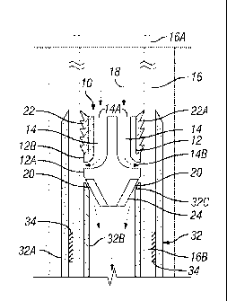
[0024] FIG. 1 illustrates a cutting dart 10, according to an embodiment of
the present
disclosure. The cutting dart 10 includes a dart body 12 with a first pathway
14 positioned there
through. The cutting dart 10 can be positioned in coiled tubing 16. By
redirecting cutting fluid
flowing through the coiled tubing 16 so that the cutting fluid impinges
against an inner surface of
the coiled tubing 16, the coiled tubing 16 can be severed. As will be
described in greater detail
below, this can be useful for releasing coiled tubing that is hung up in a
well bore.
[0025] The dart body 12 can include an inner body portion 12A and an outer
body portion
12B. The profiles of the inner body portion 12A and outer body portion 12B can
be shaped in
any manner that will redirect the cutting fluid flow, as desired. For example,
the inner body
portion 12A can have a trumpet shaped profile. Inner body portion 12A and
outer body portion
12B can be connected in any suitable manner, such as with ribs (not shown)
extending between
them. The dart body 12 can be made of any material that will resist erosion
long enough to
endure the passage of erosive slurry for the relatively short time required to
execute the cut. For
example, this could be steel stainless steel or other materials. The inner
body portion 12A and
outer body portion 12B can be made of different materials. In an embodiment,
the inner body
portion 12A can be made of materials that have increased resistance to
erosion. This is because
the inner body portion 12A may experience slightly higher erosion as the
cutting fluid is directed
radially away from the cutting dart versus the outer body 12B. Examples of
such materials
-6-
CA 02798606 2012-11-06
WO 2011/146219 PCT/US2011/034468
7
include steel or stainless steel that have been hardened by a variety of heat
treatment methods.
The inner body can also be made of ceramics or carbides such as tungsten
carbide. Alternatively,
the inner body portion 12A and outer body portion 12B can be made of the same
material.
[0026] The first pathway 14 comprises an inlet 14A at an upstream end of
the dart body 12.
An outlet 14B can be positioned at the outer circumference of the dart body
12. A second
pathway 20 is configured to allow the cutting fluid to flow past the cutting
dart 10 after the
cutting fluid impinges against the inner surface of the coiled tubing 16.
[0027] A seal 22 can be positioned around a circumference of the outer body
portion 12B of
the dart 12. The seal 22 can be any suitable type of seal that is capable of
inhibiting the flow of
fluid between the dart body 12 and the coiled tubing. The seal 22 can be
designed to be capable
of passing through coiled tubing 16 having a plurality of different inner
diameter dimensions
while still providing a seal at the location where the coiled tubing 16 is to
be cut. It is often the
case that heavy walled tubing, having a relatively small inner diameter, and
light wall pipe,
having a relatively large diameter compared to the heavy walled tubing, can be
employed. The
heavy wall tubing is generally employed near the surface, with the light wall
tubing being further
downhole. In an embodiment, seal 22 comprises a plurality of flexible ribs 22A
extending
around the outer circumference and positioned between the end of the dart body
and the outlet
14B. The ribs 22A can be made sufficiently flexible to allow the cutting dart
10 to pass through
the smaller diameter of the heavy wall tubing, while still providing the
desired seal in larger
diameter light walled tubing. For example, the ribs 22A of seal 22 can be
designed to fold over
as they go through heavy walled tubing, but extend out to provide enough
contact to seal in the
lighter walled portion where the cutting dart 10 lands. Seal 22 can be made of
any material
-7-
CA 02798606 2012-11-06
WO 2011/146219 PCT/US2011/034468
8
suitable for downhole use that provides the desired flexibility and seal
characteristics. An
example of one such material is polyurethane.
[0028] The dart body can include a nose 24 that is configured to self-
center the cutting dart
when landed in the coiled tubing 16. For example, the nose 24 can be tapered
to provide self-
centering when it contacts a tapered surface of shoulder 32C. The nose 24 is
also configured to
provide a desired second pathway 20 for allowing the cutting fluid to flow
past the cutting dart
10. For example, as most clearly shown in FIG. 2B, the nose 24 can include a
plurality of ribs
26. When the nose 24 is landed on internal shaft 32B, the ribs 26 can result
in a space between
the shoulder 32C and an inner surface 28 of nose 24, which provides the second
pathway 20. In
an embodiment, the inner surface 28 has a conical or frustoconical shape to
provide the desired
taper for self-centering the cutting dart 10. Centering the cutting dart 10
allows a more uniform
cut of the tubing wall.
[0029] The dart body 12, including the inner body portion 12A, outer body
portion 12B and
nose 24 can be formed as a single, integral piece. Alternatively, dart body 12
can be formed from
a plurality of different pieces bonded or otherwise connected together in any
suitable manner.
[0030] The cutting dart 10 can be configured to be pumped through the
coiled tubing 16 and
land on a shoulder positioned in an end connector of the coiled tubing. For
example, the cutting
dart 10 can have a length dimension that allows it to pass through coiled
tubing 16. Portions of
coiled tubing 16 may be coiled around a "drum," or reel, prior to passing
through an injector,
which lowers the coiled tubing into the well. Coiled tubing that is wrapped
around a drum can
have a bend radius that is relatively small. One of ordinary skill in the art
would understand that
the length of the cutting dart 10 can be chosen to traverse substantially the
entire length of the
-8-
CA 02798606 2012-11-06
WO 2011/146219 PCT/US2011/034468
9
coiled tubing, including the portions having a small bend radius. For example,
the cutting dart
can have a length ranging from about 2.5 inches to about 5 inches.
[0031] The cutting dart 10 can be employed as part of a coiled tubing
assembly 30. Coiled
tubing assembly 30 includes a coiled tubing 16 having a proximal end 16A at a
surface location
and a distal end 16B positioned in a well bore. An end connector 32 can be
attached to the distal
end 16B of the coiled tubing 16. A tool (not shown) can be attached to the end
connector 32.
[0032] Cutting dart 10 can be positioned proximate the end connector 32. In
an embodiment
as shown in FIG. 1, the end connector 32 can be an external connector,
typically known as
"grapple connectors" or "slip connectors." External connectors comprise an
outer housing 32A
having a grapple mechanism 34 proximate the outside surface of the distal end
16B of the coiled
tubing 16. The grapple mechanism 34 can comprise, for example, teeth
configured to bite into
the outside of coiled tubing 16, thereby fixing the external connector to the
distal end of the
coiled tubing. The grapple outer diameter is tapered to engage the conically
tapered inner
diameter of a connector outer sleeve (not shown). Rotation of the outer sleeve
engages the
grapple and creates radial engagement of the grapple teeth against the outer
sleeve.
[0033] An internal shaft 32B extends into the coiled tubing 16. Internal
shaft 32B can be
configured to provide a shoulder 32C on which the cutting dart 10 can land.
For example, the
shoulder 32C can be tapered to allow the cutting dart 10 to self-center in the
desired location. In
other embodiments, shoulder 32C can be rounded or have any other suitable
shape.
[0034] In an embodiment, the internal shaft 32B can extend up above the
grapple mechanism
34, but still below the upper portion of outer housing 32A, as illustrated in
the embodiments of
FIGS. 1 and 2. In this manner, the cutting dart 10 can be positioned to cut
the coiled tubing
above the grapple mechanism 34, thereby releasing the coiled tubing 16 from
the grapple
-9-
CA 02798606 2012-11-06
WO 2011/146219 PCT/US2011/034468
mechanism 34.This arrangement also positions the cutting dart 10 so that the
outer housing 32A
of the external connector extends over the portion of the coiled tubing 16
that will be cut. That
way, the outer housing can potentially function to contain slurry and stop it
from eroding the
customers well, as will be described in greater detail below.
[0035] In an alternative embodiment, the end connector 32 can be an
internal connector 36
(FIG. 4), which comprises an internal shaft extending into the coiled tubing
16. Internal
connector 36 can be attached to the coiled tubing by mechanically crimping
coiled tubing 16 so
that a dimple profile 16C forms in the coiled tubing and a corresponding
dimple profile 36A
forms in internal connector 36. The dimple profile 16C,36A allows the internal
connector 36 to
grip the coiled tubing 16 so as to be fixed thereto. Internal connector 36
also includes a thread
profile 36B for connecting to the top of the downhole tool 38. Shoulder 36C of
the internal
connector 36 can provide a landing seat for the cutting dart 10, similar to
the internal shaft 32B
of the external connector. In the traditional embodiment, the internal
connector 36 does not
employ an external housing, as in the external connector.
[0036] In an alternative embodiment, the internal connector 36 can be
employed with an
outer sleeve 40, illustrated in FIG. 4, which is capable of protecting the
well bore from being
damaged by the cutting fluid when the coiled tubing is cut. Outer sleeve 40
can be positioned
proximate the outside surface of the distal end of the coiled tubing between
the outlet 14B of the
cutting dart 10 (when positioned similarly as shown in FIG. 2A) and the well
bore 42. Outer
sleeve 40 can be attached in any suitable manner. For example, as shown in
FIG. 4, the outer
sleeve 40 can be held in place between a shoulder 36D of the internal
connector 36 and a box
connection of the tool 38.
-10-
CA 02798606 2014-05-07
[0037] FIG. 5 illustrates a cutting dart 50, according to another
embodiment of the present
disclosure. The cutting dart 50 is designed to be employed with a coiled
tubing string connector
52 that can be used to couple a first length of coiled tubing string 16D to a
second length of
coiled tubing string 16E. An example of one such tubing string connector 52
that is well known
in the art is the DURALINKTM spoolable connector, available from BJ Services
Company LLC.
[0038] Coiled tubing string connector 52 has a smaller inner diameter than
the coiled tubing,
and thus can potentially block passage of the dart 50, discussed above. In an
embodiment,
cutting dart 50 can be landed on a shoulder 52A, instead of on an end
connector 32 (as shown in
FIG. 1), in order to cut the first length of coiled tubing 16D above the
coiled tubing string
connector 52. However, it is sometimes desirable to cut the length of coiled
tubing 16E below
the coiled tubing string connector 52. Cutting dart 50 is designed for this
purpose.
[0039] The cutting dart 50 includes a dart body 12 with a first pathway 14
positioned there
through. The dart body 12 can include an inner body portion 12A and an outer
body portion,
similar to the cutting dart 10. However, the outer body portion of cutting
dart 50 has been
extended to include an outer body cutting portion 12C, a flexible tubular 12D,
and an outer body
sealing portion 12E. The profiles of the inner body portion 12A and outer body
portion
12C,12D,12E can be shaped in any manner that will redirect the cutting fluid
flow, as desired.
For example, the inner body portion 12A can have a trumpet shaped profile. A
seal 22, similar to
that described above with respect to cutting dart 10, can be positioned around
a circumference of
the outer body sealing portion 12E. The nose 24 of the dart body 12 can be any
desired shape,
including tapered or not tapered.
[0040] As shown in FIG. 5, the cutting dart 50 is configured to land on
shoulder 52A and
extend through coiled tubing string connector 52, so that an outlet 14B of the
pathway 14 is
-11-
CA 02798606 2012-11-06
WO 2011/146219 PCT/US2011/034468
12
positioned below the coiled tubing string connector 52. The cutting dart 50
can then be used to
cut the second length of tubing string 16E below the coiled tubing string
connector 52.
[0041] Cutting dart 50 can have any suitable length that will allow it to
extend through the
coiled tubing string connector 52. For example, the cutting dart 50 can have a
length ranging
from about 10" to about 36". The flexible tubular 12C allows the cutting dart
50 to bend when it
is passing through portions of coiled tubing 16 that may be coiled around a
"drum," or reel, and
that therefore have a bend radius that is relatively small. In this manner,
cutting dart 50 can
traverse the relatively small bend radius portions of the coiled tubing.
[0042] FIGS. 6 and 7 illustrate yet another embodiment of the present
disclosure. FIG. 6
illustrates an anchor dart 54 that can be used along with the cutting dart 10
(FIG. 1) of the
present disclosure. Anchor dart 54 can be fixed inside the coiled tubing 16 to
provide a shoulder
on which the cutting dart 10 can land. This allows the coiled tubing 16 to be
cut at any desired
location at which the anchor dart 54 can be fixed.
[0043] Anchor dart 54 can comprise a dart body 56 configured to include a
fluid pathway 58
positioned therein. The dart body 56 is not limited to the design illustrated
in FIG. 6, and can
have any suitable shape or configuration that will allow the anchor dart 54 to
pass through the
coiled tubing and be anchored at a desired position. For example, in cases
where the anchor dart
54 is used to isolate the coiled tubing, as discussed in detail below, the
dart body 56 can be
formed to be a solid mass without a fluid pathway so as not to allow fluid to
pass therethrough.
[0044] A blocking member, such as frangible disk 60, can be positioned to
selectively inhibit
the flow of fluid through the fluid pathway 58. Darts comprising a fluid
pathway and a frangible
disk arrangement are generally well known in the art for use in processes for
pumping cement
for both wellbore and formation isolation. Other suitable blocking members can
be used in place
-12-
CA 02798606 2012-11-06
WO 2011/146219 PCT/US2011/034468
13
of the frangible disk, including, for example, blow out plugs, such as a shear
pinned plug, or
valves, such as a spring loaded check valve.
[0045] The anchor dart 54 comprises a swellable elastomer 62 positioned
around an outer
circumference of the dart body 56. The swellable elastomer 62 can have any
configuration and
be positioned at any desired location on the outer circumference of the dart
body 56 that will
result in sufficient force applied to the coiled tubing 16 to fix the anchor
dart 54 in a desired
position in the coiled tubing 16 when the elastomer material swells. For
example, the elastomer
can be configured as a single ring or a plurality of fins or ribs.
[0046] The swellable elastomer 62 can comprise any suitable material that
is capable of
swelling to provide sufficient force to fix the anchor dart 54 in place while
still allowing it to
pass through the coiled tubing prior to swelling. Swellable elastomer
materials are well known in
the art. Examples of suitable elastomer materials include both natural and
synthetic rubbers.
[0047] The present disclosure is also directed to a method of cutting a
coiled tubing string in
a well bore. The method comprises pumping a dart through coiled tubing until
it lands at a
location proximate the position at which the coiled tubing is to be cut, such
as, for example, an
internal sleeve of end connector 32, as shown at FIG. 1. A cutting fluid can
be pumped through
the dart to redirect the cutting fluid radially against an inner diameter of
the coiled tubing so as
to cut the coiled tubing, as shown by fluid flow arrows 18 of FIG. 2. The
upper portion of the
coiled tubing 16 can then be removed from the well bore 42, as shown in FIG.
3.
[0048] In an embodiment, the cutting fluid can be a slurry comprising
abrasive particles. Any
suitable particles can be employed, such as sand. Sand slurries are generally
well known in the
art for use in abrasive perforating, and one of ordinary skill in the art
would be capable of
choosing a suitable sand slurry or other cutting fluid. The slurry from the
cutting dart 10 impacts
-13-
CA 02798606 2012-11-06
WO 2011/146219 PCT/US2011/034468
14
the coiled tubing surface with sufficient force so that the abrasive particles
mechanically cut
through the coiled tubing.
[0049] In another embodiment, the cutting fluid can be an acid capable of
dissolving the
coiled tubing 16. Where an acid is employed, the cutting fluid can also
include an acid inhibitor
that is capable of coating the coiled tubing 16, thereby protecting the coiled
tubing 16 as the acid
is pumped from the surface to the cutting dart 10. Such acid and acid
inhibitor systems are
generally well known in the art for use with coiled tubing applications. In
the present disclosure,
the acid forced through the cutting dart 10 impinges against the coiled tubing
surface with
sufficient force to disrupt the film forming capability of the acid inhibitor,
thereby allowing the
acid to dissolve through the coiled tubing 16 at the desired location.
[0050] A method of employing the anchor dart 54 will now be discussed.
Anchor dart 54 can
be employed in situations where it is desired to cut the coiled tubing 16 at a
location other than
where a shoulder, such as provided by an end connector or coiled tubing string
connector,
already exists. For example, this may occur where the coiled tubing string is
stuck and an
attempt to release the coiled tubing string by cutting it at the end connector
fails.
[0051] A method of using the anchor dart 54 includes inserting the anchor
dart 54 into the
coiled tubing at the surface. A measured volume of fluid can then be pumped
down the coiled
tubing 16 to displace the anchor dart 54 to a desired location inside the
coiled tubing 16. In an
embodiment, a swelling enhancer fluid 64 capable of accelerating swelling of
the elastomer 62
can be introduced into the coiled tubing 16 with the anchor dart 54. The
swelling enhancer fluid
64 can be any suitable reaction fluid or solvent that can increase the rate of
swelling. Reactive
fluids or solvents that can accelerate the swelling of the swellable elastomer
62 are well known
in the art. The combination of chemical action of the swelling enhancer fluid
64 assisted by
-14-
CA 02798606 2012-11-06
WO 2011/146219 PCT/US2011/034468
elevated temperatures causes the elastomer to swell and the anchor dart 54 to
become rigidly
affixed to the inside of the coiled tubing 16, as shown in FIG. 7. After
allowing time for a
desired amount of swelling, the frangible disk can be burst and circulation
reestablished through
coiled tubing 16.
[0052] The resulting affixed anchor dart 54 provides a shoulder within the
coiled tubing 16
on which the cutting dart 10 can land, similarly as shown in FIG. 7. The
coiled tubing 16 can
then be cut, as described above. Employing the anchor dart to cut the coiled
tubing string
partway along its length addresses the issue of the coiled tubing becoming
stuck by sand or fill
falling down and bridging around the outside of the coiled tubing higher up
the well, rather than
at the end connector. This operation of fixing the anchor dart 54 and cutting
the coiled tubing 16
can be repeated multiple times at different locations in the coiled tubing 16
until the remaining
coiled tubing string is no longer stuck and can be retrieved to the surface.
[0053] The anchor dart 54 can also be employed to isolate the coiled tubing
string. For
example, after making the cut with either the cutting dart 54 or some other
cutting means, a
check valve proximate the end of the coiled tubing string is lost, and fluids
from the wellbore can
enter the coiled tubing string at the location of the cut. The coiled tubing
is therefore "live" while
it is being pulled from the well. Under some conditions, it may be considered
too risky to
retrieve the live coiled tubing string under internal well pressure.
[0054] In such situations, the anchor dart 54 can be pumped downhole to
within a desired
distance from where the coiled tubing string has been cut and allowed to swell
and lock into
place. Alternatively, if well pressures cannot be managed within the burst
rating of the frangible
disk, a solid anchor dart designed to handle the well pressures or a dart with
a spring loaded
check valve can be employed; or the anchor dart 54 can be used as a landing
point for a regular
-15-
CA 02798606 2012-11-06
WO 2011/146219 PCT/US2011/034468
16
dart with a higher pressure rating that can isolate the coiled tubing string
after the cut. In this
manner, the anchor dart 54 can be used to isolate the coiled tubing string
prior to retrieving the
coiled tubing 16 from the well.
[0055] In still other situations, the anchor dart 54 can be employed to
isolate the coiled
tubing where, for example, the coiled tubing has been punctured to form a hole
therein through
which hydrocarbons can leak. The method can include pumping the anchor dart 54
through the
coiled tubing until it is positioned at a location at which the coiled tubing
is to be isolated, such
as a location proximate the hole. The swellable elastomer can then be expanded
to fix the anchor
dart inside the coiled tubing and thereby inhibiting the flow of fluid through
the coiled tubing. In
this manner, the anchor dart 54 can be fixed to isolate the hole in the coiled
tubing from the
portion of the coiled tubing pressurized by hydrocarbon fluid flowing from the
well. In this
manner, the amount of hydrocarbon fluid leaking through the hole can be
reduced.
[0056] When isolating the coiled tubing, the dart body 56 can include a
pathway 58 for
conducting fluid, along with a blocking member for selectively inhibiting
fluid flow through the
pathway, as discussed above. Alternatively, the dart body can be formed as a
solid mass without
a pathway capable of conducting fluid therethrough.
[0057] Although various embodiments have been shown and described, the
present
disclosure is not so limited and will be understood to include all such
modifications and
variations as would be apparent to one skilled in the art.
-16-