Note : Les descriptions sont présentées dans la langue officielle dans laquelle elles ont été soumises.
-11-
WO 2011/143483 PCT/US2011/036327
1
HIGH PRESSURE COFFEE BREWER
TECHNICAL FIELD
[0001] The present application relates generally to beverage
brewing mechanisms and, more specifically, to brewers for brewing
beverages requiring different brewing pressures and temperatures.
BACKGROUND
[0002] Systems for brewing beverages such as espresso must
often be made specific to a particular brew (e.g., North American
coffee, north European and/or Italian espresso, etc.) or
adjustable to prepare multiple types of beverages. One category
of brewer design, for example, uses an internal valve and/or a
variable volume brew chamber for producing both low and high
pressure brewed beverages. Such systems are described in EP 1
267 685 B1 and EP 1 267 686 B1, the content of which is
incorporated herein by reference. Within those designs, movement
of a spring-biased internal shuttle opens or closes a valve to
alter the size of an opening for an outlet from the brewing
chamber, thereby changing the pressure within the brewing
chamber. Such movement represents a point of mechanical wear
that can, over time, result in inconsistency in the quality of
the beverage brewed.
[0003] There is, therefore, a need in the art for an improved
beverage brewing system.
-11-
WO 2011/143483 PCT/US2011/036327
2
SUMMARY
[0004] A brewer for brewing different beverages requiring
different brewing pressures does not employ an internal valve
adjusting an outlet opening to achieve the different pressures.
Instead, compression of grinds within the brewer and pressure of
water injected to brew the beverage is employed to control the
brewing pressure, achieving a greater consistency of brew quality
over time. Overheating is implemented for certain beverages
based on a time since a last vend, and a back check valve between
a flow meter and pump provides greater control over the pump
output.
[0005] Before undertaking the DETAILED DESCRIPTION below, it
may be advantageous to set forth definitions of certain words and
phrases used throughout this patent document: the terms
"include" and "comprise," as well as derivatives thereof, mean
inclusion without limitation; the term "or," is inclusive,
meaning and/or; the phrases "associated with" and "associated
therewith," as well as derivatives thereof, may mean to include,
be included within, interconnect with, contain, be contained
within, connect to or with, couple to or with, be communicable
with, cooperate with, interleave, juxtapose, be proximate to, be
bound to or with, have, have a property of, or the like; and the
term "controller" means any device, system or part thereof that
controls at least one operation, such a device may be implemented
in hardware, firmware or software, or some combination of at
least two of the same. It should be noted that the functionality
associated with any particular controller may be centralized or
distributed, whether locally or remotely. Definitions for
certain words and phrases are provided throughout this patent
document, those of ordinary skill in the art should understand
that in many, if not most instances, such definitions apply to
prior, as well as future uses of such defined words and phrases.
-11-
WO 2011/143483 PCT/US2011/036327
3
BRIEF DESCRIPTION OF THE DRAWINGS
[0006] For a more complete understanding of the present
disclosure and its advantages, reference is now made to the
following description taken in conjunction with the accompanying
drawings, in which like reference numerals represent like parts:
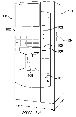
[0007] FIGURE 1A is a front perspective view of a coffee
vendor for delivering brewed beverages requiring different
brewing pressures according to one embodiment of the present
disclosure;
[0008] FIGURE 1B is a front view of the vendor of FIGURE 1A
with the service door open, revealing internal features of the
vendor;
[0009] FIGURE 2 is a block diagram of portions of the control
system for the vendor of FIGURES 1A and 1B;
[0010] FIGURE 3A is a vertical cross-section of portions of a
brewer within the vendor of FIGURES 1A and 1B;
[0011] FIGURE 3B is a sectional view of the brewer depicted in
FIGURE 3A taken at section lines 3B-3B;
[0012] FIGURES 4A through 4D are sectional views similar to
FIGURE 3B that illustrate operation of the brewer of FIGURES 3A
and 3B;
[0013] FIGURE 5 is a view from the rear into the cabinet of
the vendor of FIGURES 1A and 1B, with cabinet sidewalls removed
to show additional components employed in brewing beverages; and
[0014] FIGURE 6 is a high level flow diagram illustrating a
process for brewing a beverage within the vendor of FIGURES 1A
and 1B.
-11-
WO 2011/143483 PCT/US2011/036327
4
DETAILED DESCRIPTION
[0015] FIGURES 1A through 6, discussed below, and the various
embodiments used to describe the principles of the present
disclosure in this patent document are by way of illustration
only and should not be construed in any way to limit the scope of
the disclosure. Those skilled in the art will understand that
the principles of the present disclosure may be implemented in
any suitably arranged vending machine currency handling system.
[0016] FIGURE 1A is a front perspective view of a coffee
vendor for delivering brewed beverages requiring different
brewing pressures according to one embodiment of the present
disclosure. The vendor 100 includes a cabinet 101 with a door
102 on the front of the cabinet. Mounted on the door 102 is a
display 103 such as a continuous or segmented liquid crystal
display (LCD), for displaying messages to the customer. Also
mounted on the door 102 is a selection keypad 104 with buttons
optionally associated with selection decals or other identifiers
for enabling the customer to make a vend selection. One or more
of slot(s) 105 and button(s) 106 communicates with a payment
system inside the cabinet 101, such as a coin acceptor, a bill
validator and/or recycler, or both. In the exemplary embodiment,
a single slot providing access to a coin acceptor is provided,
together with a coin return button that, when actuated, causes
deposited coins to be returned to the coin return 107. Also
mounted in the front of door 102 is a delivery station 108, to
which a cup and the brewed beverage are delivered for removal by
the customer.
[0017] FIGURE 1B is a front view of the vendor 100 of FIGURE
1A with the door 102 open, revealing internal features of the
vendor 100. Mounted on the inside of door 102 is a service
keypad 108, which is connected to a vending machine controller
(not visible in FIGURE 1B) also mounted on the inside of door
102. Cup turret 109 mounted on the inside of door 102 holds
-11-
WO 2011/143483 PCT/US2011/036327
empty cups for delivery by cup drop unit 110 to cup catcher 111
at the delivery station 108. Inside cabinet 101, a fresh beans
canister 112 holds coffee beans to be ground for preparation of
coffee-based beverages, and ingredients canisters 113 hold other
5 ingredients (e.g., flavorings) for use in brewing beverages.
Canisters 112 and 113 are communicably coupled to dispense head
115, to deliver predetermined quantities of ingredients thereto.
Wasted from brewer 114 is received by container 116. Brewed
beverages from brewer 114, mixed with other ingredients from
canisters 113, are delivered by dispense head 115 to a cup held
within cup catcher 111 at the delivery station 108. The customer
may retrieve the cup and contents from the delivery station.
[0018] FIGURE 2 is a block diagram of portions of the control
system 200 of the vendor 100 of FIGURES 1A and 1B. Control
system 200 includes a vending machine controller (VMC) 201
coupled by wiring or other means for communicating signals to
and/or receiving such signals from: a customer interface 202,
which includes at least customer display 103 and keypad 104 and
service keypad 108 in the exemplary embodiment; payment system
electronics 203, including at least the coin acceptor mounted
behind slot 105 and coin return button 106 in the exemplary
embodiment; dispensing system controls 204 controlling rotation
of cup turret 109 and release of cups from cup turret 109 through
cup drop unit 110 to cup catcher 111; product storage valves 205
controlling dispensation of beans from bean canister 112 to the
grinder (located at the top of the brewer) and ingredients from
the ingredients canisters 113 to the dispensing head 115; heater
controls 206; an optional delivery sensing system 207; and
grinder and brewer controls 208, controlling operation of the
brewer 114 and the associated grinder (not separately visible in
FIGURE 1B). Controller 201 is programmed to operate the controls
coupled thereto in a manner known in the art, and as described in
further detail below.
-11-
WO 2011/143483 PCT/US2011/036327
6
[0019] Those skilled in the art will recognize that the
complete structure of a vending machine is not depicted in the
drawings, and the complete details of the structure and operation
of the brewed beverage vendor is not described herein. Instead,
for simplicity and clarity, only so much of the structure and
operation of a brewed beverage vendor as is unique to the present
disclosure or necessary for an understanding of the present
disclosure is depicted and described. Additional details
regarding the structure and operation of one brewed beverage
vendor of the type in which the improvements of the present
disclosure may be implemented may be found by reference to an
"Evolution" model brewed beverage vendor, available from Crane
Merchandising Systems and described in Evolution Technical
Manual, part no. PR10909000 issue C 02/09 available at
www.cranems.co.uk/techdocs/PR10909000revCsml.pdf and/or Evolution
Operators Manual, part no. PR 10908000 issue B 04/06 available at
www.cranems.co.uk/techdocs/PR10908000IssueB.pdf, both of which
are incorporated herein by reference.
[0020] Brewer 114 is adapted in the present disclosure to brew
beverages requiring different pressures, such as coffee (lower
pressure) and espresso (higher pressure). Unlike the systems
described above, however, the outlet aperture is not changed in
order to achieve the requisite pressure. Instead, the grind of
the coffee within the brewer, together with the pressure applied
to the grind and the pressure of the water supplied to the
brewer, is employed to achieve the required brewing pressure.
[0021] FIGURE 3A is a vertical section of portions of a brewer
114 within the vendor 100 of FIGURES 1A and 1B. FIGURE 3B is a
cross-section of the brewer 114 depicted in FIGURE 3A taken at
section lines 3B-3B. Brewer 114 includes a housing formed in
part by a cylinder 301. A press 302 that is movable within the
cylinder 301 is provided with seals 303-304. Apertures 305 in
fluid communication with dispensing apertures 306 are bounded by
-11-
WO 2011/143483 PCT/US2011/036327
7
seals 303-304 and may be selectively brought into fluid
communication with a supply line 307 for heated, pressurized
water supplied by pump 308 by movement of press 302. Press 302
is connected by drive rod 309 to a crank pin 310, which in turn
forms part of a crankshaft 311 connected to motor 312. Switches
209 and 210 controlling pump 308 and motor 312 are among the
grinder and brewer controls 208. In addition, a pump motor
current sensor 211 is employed to determine compression of the
grinds as described in further detail below.
[0022] A rocker arm 313 includes control apertures 314 and 315
each having an edge engaging on curved disk 316, and is biased by
two coil springs 317. Rocker arm 313 includes a cover 318 in
which a filter plate 319 and filter 320 are fitted. Filter plate
319 is provided with a sealing ring 321, fitting against an end
of the cylinder 301. Curved disk 316 is fitted on the crankshaft
311 and includes recesses 322 and 323. Cam 324 in control
apertures 314 and 315 of rocker arm 313 is designed to engage
curved disc 316 or recesses 322, 323. Outlet 325 for the brewed
beverage from the brewing chamber formed by cylinder 301, press
302 and filter plate 319/filter 320 is connected by outlet piping
and/or tubing 326 to the dispense head 115. As shown, outlet 325
does not include a valve or other movable mechanism for
controlling an effective size of the outlet (and therefore
pressure within the brewing chamber).
[0023] FIGURES 4A through 4D illustrate operation of the
brewer of FIGURES 3A and 3B. The view depicted is similar to
that of FIGURE 3B. During a first phase of the beverage-brewing
process (FIGURE 4A) the rocker arm 313 is situated in such a
position that the aperture of cylinder 301 is open, so that
coffee grinds 40 may be fed by gravity from a grinder (not shown)
located above the brewing chamber onto the press 302. The
quantity and type of grind of coffee grinds is dependent, for
example, on the desired product. For example, a small quantity
-11-
WO 2011/143483 PCT/US2011/036327
8
of a first type of grind is required for "ordinary" or North
American coffee, and a larger quantity of a second type of grind
is required for espresso coffee.
[0024] In the position illustrated in FIGURE 4A, rocker arm
313 rests against stop 325 of the housing for brewer 114. Cam
324 is situated in recess 323 and, through the action of coil
springs 317, the rocker arm 313 is pressed away from cylinder
301. In addition, the coil springs 317 also to generate a
clockwise (as seen in FIGURE 4A) rotational force on rocker arm
313, biasing rocker arm 313 toward a position over the end of
cylinder 301.
[0025] Motor 312 turns the crankshaft 311 clockwise, with
press 302 moving downwards and at the same time rocker arm 313
moved to the left until positioned over the open end of cylinder
301. Further clockwise rotation of crankshaft 311 pulls rocker
arm 313 downwards since, once the limit of motion to the left is
reached, on reaching the end of the recess 323 the cam 324 is
pressed downwards by the curved disk, against the spring force of
springs 317. As a result, seal 321 of filter plate 319 engages
the end of cylinder 301. Press 302, driven by motor 312 still
turning clockwise, then moves upwards again, so that coffee
grinds 40 are compressed by press 302 against the filter plate
319 as depicted in FIGURE 4B. Depending on the quantity of
coffee, the press will stop at a higher or lower level, but with
region containing grinds 40 always in communication with the
supply line 307. The proper compression of the grinds 40 for the
brew desired is controlled by controller 201 based on the current
draw of motor 312, as described in further detail below.
[0026] Heated water is then supplied through supply line 307
at a pressure controlled by controller 201 by controlling the
output of the pump 308 to obtain the desired product. For
traditional North American coffee, a relatively low pressure will
be used, while for espresso coffee the pressure will be higher
-11-
WO 2011/143483 PCT/US2011/036327
9
(for example, 9-11 bar). In both cases the heated water passes
into the grinds 40 through apertures 306 and leaves the grinds 40
again by way of filter plate 319 and between filter plate 319 and
cover 318 to be dispensed through outlet 325, during which
process the grinds 40 are retained by the filter plate.
[0027] After the beverage has been brewed, motor 312 is driven
counter-clockwise (as seen in FIGURE 4C). During this return
motion the "coffee-tablet" 41 of compressed grinds remains
adhering to the cylinder 301, and not to the rocker arm 313
because of a scraper strip. The motion of rocker arm 313
progresses until cam 324 falls into recess 323 and, owing to the
spring force, rocker arm 313 moves upwards to break the seal
between seal edge 321 and the top end of cylinder 301. The
rocker arm 313 then moves along with the crankshaft 311. As
rocker arm 313 moves to the position shown in FIGURE 4C, the
press 302 moves up. The rocker arm 313 is then pressed downwards
by the fact that crank 311 continues rotating and the "end" of
recess 323 is reached. Upon further rotation of crank 311, press
302 moves back to top center, pushing tablet 41 above the level
of cylinder 301. Cam 324 then goes into recess 322 and, under
the influence of coil springs 317, rocker arm 313 moves upwards
and to the left, pushing the tablet 41 off the surface of press
302 as shown in FIGURE 4D. On further rotation, when there is
engagement with the "end" of recess 322, cam 30 rotates until the
rocker arm 313 returns to original position shown in FIGURE 4A.
[0028] Unlike the internal valve systems described above,
brewer 114 does not include a valve in the opening 325 above
filter 320 leading to piping/tubing 326, adjusted to control
brewing pressure by changing the size of the opening allowing
brewed beverage to flow out of the brewer. Instead, brewer 114
relies on the grind of the coffee employed, the force applied by
press 302 (as determined from the current draw of motor 312
driving press 302) and the pressure of water injected into the
-11-
WO 2011/143483 PCT/US2011/036327
brewer 114 through supply line 307 by pump 308. The press motor
current sensor 211 may be employed to determine the compression
being applied to the grinds, as greater compression will require
higher current draw. The pump 308 may be operated at variable
5 speeds to generate different pressures of the heated water being
pumped. Thus, brewing a North American coffee would involve
producing a first quantity and first type of grinds, applying a
first compression to those grinds during brewing and pumping
water in at a first pressure during brewing, while brewing a
10 north European espresso would involved producing a second
quantity and second type of grinds, applying a second compression
and pumping water at a second pressure.
[0029] FIGURE 5 is a view from the rear into the cabinet of
the vendor of FIGURES 1A and 1B, with cabinet sidewalls removed
to show additional components employed in brewing beverages. A
350 milliliter (ml) brass heater 500 having an internal heating
element is employed to heat water supplied to vendor 100.
Depending on the length of time since the vendor 100 last
dispensed a drink, the heating algorithm applied by controller
201 to heater controls 206 for heater 500 varies depending upon
the time since the last beverage was vended. The heating element
is generally controlled by controller 201 based on thermocouple
temperature measurements, to maintain the water in heater at a
predetermined temperature. However, when the user selects
certain beverages, such as an espresso, the controller 201
activates an overheating algorithm as set forth in TABLE I below.
Time between vends (MINS)
From To Heater on time
0.00 1.59 4.00
2.00 5.59 5.00
6.00 9.59 6.00
10.00 13.59 7.00
14.00 17.59 8.00
-11-
WO 2011/143483 PCT/US2011/036327
11
18.00 21.59 9.00
22.00 25.59 10.00
26.00 29.59 11.00
30.00 * 16.00
TABLE I
Overheating time is set to 0 is the vendor is in standby mode or
is not preparing beverages requiring overheating. The heater on
time is measured from when the brewer 114 starts to move. During
the beverage delivery period, the heater element is switched off
until delivery is complete (the pump is switched off) and the
overheating algorithm is reset.
[0030] From heater 500, water flows through a pressure relief
valve 501 to a flow meter 502 controlling the amount of water
that is injected into the brewer 114. (No description is made of
the tubing connecting these elements, since the necessity of such
tubing is understood). In the present disclosure, a back check
valve 503 is situated between the flow meter 502 and the pump 308
to prevent spurious output due to action (e.g., vibration) of the
pump 308. The internal valve designs described above do not
employ such flow regulation. In addition, only a single pump 308
is employed to pump water into brewer 114, whereas the internal
valve designs described above generally employ two separate
pumps.
[0031] FIGURE 6 is a high level flow diagram illustrating a
process for brewing a beverage within the vendor 100 of FIGURES
1A and 1B. The process 600 is executed by controller 201, and
begins with a customer selection of a beverage being received
(step 601). A determination is made as to whether the customer's
beverage selection required overheating by heater 500 (step 602),
and if so overheating is applied based on the lapse of time since
a last vend (step 603). Concurrently therewith, controller 201
may set the parameters for operation of the bean grinder (i.e.,
-11-
WO 2011/143483 PCT/US2011/036327
12
quantity and/or type of grind), the pump pressure and the press
compression corresponding to the customer's beverage selection
(step 604). Once the water is heated to the correct temperature
(step 605), the grinder is activated (step 606) to produce the
correct quantity and type of grind within the grinder for the
selected beverage. The motor driving the press is then activated
(step 607) to provide the required compression on the grinds
within the brewer. The compression is determined based upon the
current draw by the press drive motor. Next, the pump is
activated (608) to provide water of the correct temperature at
the pressure needed to produce the selected beverage within the
brewer. The process then becomes idle until another beverage
selection is made. Those skilled in the art will recognize that
some steps are not explicitly shown, such as activating controls
to release beans from the bean canister to the grinder or
activating one or more valves allowing other ingredients to be
mixed with the brewed beverage at the dispense head.
[0032] The present disclosure eliminates the need for an
internal valve in brewing different types of beverages requiring
different brewing pressure, employing compression of the grinds
and water pressure to achieve the correct brew. A temperature
algorithm matches heating of the water to the beverage being
brewed, and a back check valve between a flow meter and pump
prevents spurious output. In this manner, a greater consistency
in the brew with less potential for mechanical wear is achieved.
[0033] Although the present disclosure has been described with
exemplary embodiments, various changes and modifications may be
suggested to one skilled in the art. It is intended that the
present disclosure encompass such changes and modifications as
fall within the scope of the appended claims.