Note : Les descriptions sont présentées dans la langue officielle dans laquelle elles ont été soumises.
CA 02799441 2012-11-13
WO 2011/153401 PCT/US2011/039009
METHOD AND SYSTEM FOR NON-INTRUSIVE LOAD MONITORING
AND PROCESSING
BACKGROUND
[0001] The present disclosure generally relates to a method and system for
monitoring
load characteristics of electric loads in a residential or commercial setting
through the use of an
electricity meter and identifying the specific types of loads and their
respective operating
conditions. More specifically, the present disclosure relates to a method and
system that
monitors the load characteristics of electrical loads and communicates the
identification
information related to each of the loads to a system operator or a third party
for review, analysis
and possible direct communication to the owner/operator of the electrical
load.
[0002] Electric utilities in commercial facilities are interested in
monitoring detailed
electric power consumption profiles of their customers to analyze the amount
of energy being
utilized and for monitoring peak load levels and the time of such peaks.
Typically, this energy
consumption is monitored for the complete residence or commercial facility,
since monitoring
the energy consumption of each individual appliance contained within the
residence or facility
typically requires placing a monitoring device on each of the electric loads
within the facility.
However, acquiring knowledge of the energy consumption of each individual load
within the
facility would provide additional information for both the owner and the
utility in monitoring
energy consumption.
[0003] In an attempt to monitor energy consumption by each individual electric
load
within the facility, systems and methods have been developed to track the
energy consumption of
electric loads within the facility without requiring separate monitoring of
each of the loads. One
technique to carry out this type of monitoring is referred to as non-intrusive
load monitoring.
Non-intrusive load monitors (NILM) are devices intended to determine the
operating schedule of
major electrical loads in a building from measurements made outside of the
building. Non-
intrusive load monitoring has been known since the 1980's (see Hart U.S.
Patent No. 4,858,141).
Non-intrusive load monitoring is generally a process for analyzing the changes
in the voltage and
currents going into a house and, from these changes, deducing what appliances
are used in the
house as well as their individual energy consumption. The NILM compares the
energy
consumption information from the home, such as recorded at an electric meter,
and compares the
energy consumption information to known load profiles for different types of
electrical loads.
-1-
CA 02799441 2012-11-13
WO 2011/153401 PCT/US2011/039009
[0004] Although non-intrusive load monitoring has been known for many years,
utilities
and other interested parties have been unable to leverage the information
obtained from a non-
intrusive load monitor.
SUMMARY
[0005] The present disclosure relates to a system and method for the non-
intrusive
monitoring and identification of one or more electrical loads located within a
facility. The
system generally includes an electricity meter positioned to monitor the load
characteristics, such
as voltage, current and phase, of a series of loads in a residential or
commercial setting. The
electricity meter includes both a current monitor and a voltage monitor that
receive the load
characteristics for the facility and convert the load characteristics to a
digital voltage signal and a
digital current signal.
[0006] In one embodiment of the disclosure, a correlator is contained within
the
electricity meter and is configured to receive the digital voltage signal and
the digital current
signal and compare select attributes of the signals to a plurality of
representative load signatures
also stored within the electricity meter. Based up on the comparison between
the digital voltage
signal and the digital current signal and the stored, representative load
signatures, the correlator
within the electricity meter identifies a particular model (e.g., manufacturer
model) and/or type
(e.g., type of appliance) of various electrical loads operating within the
monitored facility.
[0007] The load identification information, as well as time of day usage
information, is
relayed from the electricity meter to a remote location, such as a back end
server provided by the
utility or a separate data aggregator. The load identification information
could be stored for a
period of time in the electricity meter before being relayed to the remote
location or could be
relayed in near real-time. In an alternate embodiment, the remote utility back
end or data
aggregator includes the load profile storage device, such as non-volatile
memory, as well as the
correlator such that the load identification step is performed outside of the
electricity meter. In
each case, the correlator and load profile storage device combine to identify
the specific type
and/or of electric load operating at the monitored facility.
[0008] Once the specific type and/or model of electric load has been
identified by a
comparison between the operating load profile(s) for the facility and the
stored load signatures,
the system and method of the present disclosure can send email or other types
of messages to the
-2-
CA 02799441 2012-11-13
WO 2011/153401 PCT/US2011/039009
home/business owner regarding the specific operation of the electric loads
within the facility. As
an example, messages may be sent to the home/business owner suggesting a
change in the time
of operation of the electric loads to reduce the home/business owner's
electric utility bill by
operating the loads during off-peak periods. Additionally, information can be
sent to the
home/business owner suggesting replacement of electric loads or suggesting
service that needs to
be performed on the electric loads to have the electric loads operating in a
more efficient manner.
[0009] In yet another contemplated embodiment, the electric load
identification
information can be relayed to a third party for a subscription fee paid to the
utility. The third
party may be a product manufacturer, a product distributor, a product retailer
or a third party data
provider. A third party data provider, in turn, could contract with the
product manufacturer,
product distributor or product retailer to provide service leads at a fee.
[0010] Various other features, objects and advantages of the invention will be
made
apparent from the following description taken together with the drawings.
BRIEF DESCRIPTION OF THE DRAWINGS
[0011] The drawings illustrate the one mode presently contemplated of carrying
out the
disclosure. In the drawings:
[0012] Fig. 1 is a schematic illustration of a non-intrusive load monitoring
system of the
present disclosure;
[0013] Fig. 2 is an alternate embodiment of the non-intrusive load monitoring
system of
the present disclosure;
[0014] Fig. 3 is an illustration of the various different types of load
profiles that can be
stored in the system of the present disclosure;
[0015] Fig. 4 is a representative load on an electricity meter;
[0016] Fig. 5 depicts current and voltage profiles that occur after a
triggering event; and
[0017] Fig. 6 is a flowchart illustrating one possible operating procedure
utilized while
operating within the scope of the present disclosure.
DETAILED DESCRIPTION OF THE INVENTION
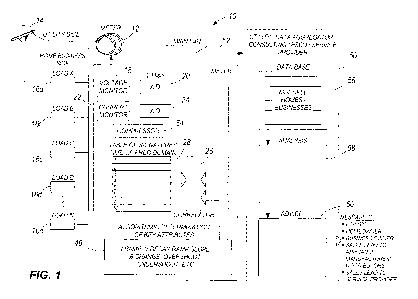
[0018] Fig. 1 is a block diagram of a non-intrusive load monitoring (NILM)
system 10.
The NILM system 10 illustrated in Fig. 1 includes an electricity meter 12
connected to a supply
-3-
CA 02799441 2012-11-13
WO 2011/153401 PCT/US2011/039009
of electricity from a utility service provider 14. Electric power from the
utility service provider
14 travels through the meter 12 and is distributed to a series of individual
loads 16a-16n. The
individual loads 16 receive electricity through the meter 12 such that the
meter 12 monitors and
determines the amount of electricity consumed by the aggregate combination of
the loads 16a-
16n, Each of the individual loads 16a-16n is typically contained within a
single facility, such as
a home residence or commercial facility. The electricity meter 12 accumulates
the amount of
energy consumed by the facility and reports the total energy consumption to a
utility for billing
and monitoring purposes.
[0019] Non-intrusive load monitoring can be used to determine the operating
schedule of
individual electric loads contained within a facility by monitoring and
analyzing the energy
consumption for the entire facility. In the embodiment shown in Fig. 1, non-
intrusive load
monitoring can be performed on the aggregated energy consumption for the loads
16a-16n to
identify the particular types and models of the loads 16a-16n contained within
the facility. Non-
intrusive load monitoring is a known technique, as set forth in "Non-Intrusive
Appliance Load
Monitoring System Based On A Modern kWH-Meter ", Technical Research Center of
Finland,
ESPOO 1998, as well as U.S. Patent No. 4,858,141. The NILM monitoring
techniques described
in the two references set forth above disclose the concept of comparing a load
profile from a
facility to known load signatures for different types of electric loads and,
based upon the
comparison, identifying the type of load contained within a facility. The
disclosure of the
references set forth above is incorporated herein by reference.
[0020] In the embodiment shown in Fig. 1, the electricity meter 12 includes a
series of
internal components that allow the electricity meter 12 to function as part of
a non-intrusive load
monitoring system. The electricity meter 12 includes a voltage monitor 18 that
monitors the
voltage consumption of the series of electrical loads 16. The voltage monitor
18 includes an
analog to digital converter 20 that samples the analog voltage signal at, for
example, a sample
rate of 20 ks/s.
[0021] In addition to the voltage monitor 18, the meter 12 includes a current
monitor 22
that also feeds an analog to digital converter 24. The analog to digital
converter 24 samples the
analog current signal at, for example, 20 ks/s. Although sampling rates for
both the A/D
converters 20, 24 are described, it should be understood that the A/D
converters could sample the
signals at different sampling rates.
-4-
CA 02799441 2012-11-13
WO 2011/153401 PCT/US2011/039009
[0022] In the embodiment shown in Fig. 1, the sampled voltage and current
signals from
the A/D converters 20, 24 are each fed to a correlator 26. The correlator 26
is a component of, or
operates with, the electricity meter 12 and is programmed and functions to
compare the sampled
voltage and current signals to a table of stored load signatures for both a
plurality of different
types of electric loads as well as a plurality of different electric load
models within each of the
electric load types. The table of load signatures is generally indicated by
reference numeral 28 in
Fig. 1. The table of signatures 28 can include as many load signatures as
desired, depending
upon the memory capabilities of the electricity meter 12.
[0023] Fig. 3 illustrates one possible structure for the table of signatures
28. In the
illustration of Fig. 3, a first load type 30 is illustrated, load type 1. In
this embodiment, load type
I represents the general category of air conditioners. However, it should be
understood that load
type I could be other types of electrical loads, such as hot water heaters,
pool pumps, baseboard
heaters, electric cars, hair dryers, computers, televisions or any other type
of relatively
significant electricity-consuming loads that could be utilized within the
facility being monitored.
[0024] Load type I, shown by reference numeral 30, is a first level of a
memory tree
structure. The memory tree structure includes a series of specific model types
32-38 that fall
within the general category of load type I. As an example, Model A could be a
specific model
provided by a first air conditioner manufacturer. Model B, illustrated by
reference numeral 34,
could be a different model number also from the first manufacturer. Model C,
referred to by
reference numeral 36, could be a model from a second air conditioner
manufacturer.
[0025] The primary profile 32 for Model A is shown as one of the load
signatures stored
in the memory of the electricity meter. In addition to the general operating
signature, the
database could also store a startup signature40, a first fault/failure
signature 42, a second
fault/failure signature 44 and possibly a third fault/failure signature 46 (or
more). Each of these
load signatures is provided by the manufacturer of the electricity-consuming
appliance or a third-
party profile generator. The fault/failure signatures 42-46 can represent
various different
common failure modes for the electrical load, such as the failure of a
compressor in an air
conditioner, the failure of a starting capacitor, or any other fault mode for
the electrical load and
can be detected through a monitored load profile. It should be understood that
under each of the
model types, various different startup signatures, fault signatures and
failure signatures can be
provided depending upon the specific manufacturer for the appliance. The use
of both the
-5-
CA 02799441 2012-11-13
WO 2011/153401 PCT/US2011/039009
startup signature and the various fault/failure signatures allows the non-
intrusive load monitoring
system of the present disclosure to not only identify the particular type and
model of the
electrical load, but also to diagnose operating problems that may occur or are
present during
operation of the electrical load. The significance of this monitoring feature
will be described in
detail below.
[0026] Referring back to Fig. 1, the correlator 26 receives the voltage and
current signals
from the analog to digital converters 20, 24 as well as uploading algorithm
information from an
algorithm database 48. The algorithm database 48 includes an identification of
which key
attributes of both the voltage and current signals that the correlator 26
should utilize to compare
the voltage and current information from the meter 12 to the stored signature
profiles from the
table of signatures 28. As an illustrative example, the correlator 26 will
compare between ten to
twelve key attributes from each of the input signals to the same attributes in
the load profiles
from the table of signature profiles 28. These attributes may include the
current ramp upon
initial activation of the load, the voltage decay ramp slope, the phase
change, overshoot,
undershoot, as well as other key attributes that can be identified and
utilized to compare the
voltage and current profiles from the electricity meter to the stored
signature profiles. The
various key attributes are detected in the load profile of the facility being
monitored. Although
several possible key attributes are set forth above, it should be understood
that other types of
attributes could be detected depending upon the type of load and the
fault/failure profiles for
each. The algorithm database may indicate both the type and number of key
attributes use for
the comparison and may vary based on the signature profile to which the
voltage and current
information are compared.
[0027] The signature profiles stored in the table of signature profiles 28 are
provided by
manufacturers and identify key attributes in the activation and/or operation
of the electric load
that are utilized to compare a load profile from the facility to stored
information. Although in the
illustrative example the correlator compares between ten to twelve key
attributes, it should be
understood that different numbers of attributes could be utilized while
operating within the scope
of the present disclosure. In general, the larger the number of attributes
compared between the
measured load profile from the facility and the signature profiles stored in
the table of signature
profiles 28 will increase the accuracy of the comparison process. However, the
larger number of
key attributes that are compared will also increase the processing
requirements for the electricity
-6-
CA 02799441 2012-11-13
WO 2011/153401 PCT/US2011/039009
meter and the volume of information that must be stored for each of the load
profiles from the
facility. It is contemplated that a comparison of between ten to twelve key
attributes will
typically be adequate to perform the comparison process of the present
disclosure. In some
cases, less than ten to twelve key attributes will be sufficient, depending
upon the load.
[0028] Based upon the comparison of the load profile from the meter 12 to the
series of
load signatures stored in the table of signature profiles 28, the correlator
26 can identify what
type of load is being activated and/or operating at the facility.
Alternatively, the correlator 26
can instead initially determine the specific model of the electric load at the
facility without
having to first identify the type of load. In some embodiments, the correlator
26 can determine
both the type and model of the load.
[0029] In some embodiments, the correlator 26 calculates a confidence
indicator that is
based upon the degree of matching between the analyzed profile and the
signature profiles
contained within the table of signature profiles 28 (e.g., the number of
attributes used or
matched, how well the attributes from the analyzed profile align with those of
the signature
profiles, etc.). The confidence value can range, for example, between 0-100
depending upon the
level of matching detected. It is contemplated that a particular load profile
from the facility may
correspond to a signature profile for different models of a certain type of
load. As an example, a
measured load profile may correspond to different models of an air conditioner
from the same
manufacturer or different models of air conditioners from different
manufacturers. After each
measurement cycle, the correlator selects the identified type of load and
specific model that has
the highest confidence value as the most likely type of electric load being
operated within the
monitored facility. The correlator 26 provides a confidence value during each
measurement
cycle and, over time, can more accurately determine and estimate the type of
load at the facility
based upon a history of analysis.
[0030] As illustrated in Fig. 1, the meter 12 relays information to a
utility/data aggregator
50 over a wired or wireless connection 52. In the embodiment shown in Fig. 1,
the utility 50 can
be a utility service provider or, alternatively, can be other types of data
aggregators, consulting
companies or different types of service providers that are designated to
receive information from
the electricity meter 12. Throughout the rest of the disclosure, the term
"utility" will be utilized;
however, it should be understood that the utility 50 could be an independent
service provider,
-7-
CA 02799441 2012-11-13
WO 2011/153401 PCT/US2011/039009
data aggregator (e.g., an advertiser or advertising service), or any other
facility that receives
information from the electricity meter 12.
[0031] The electricity meter 12 includes a data compressor 54 that compresses
data prior
to transmitting the data over the wireless connection 52. It is contemplated
that the data
compressor could be utilized to compress information before the information is
transmitted in
various different manners. In one contemplated embodiment, the utility meter
12 compresses all
of the measured voltage and current information, as well as the analysis
generated by the
correlator 26. In such an embodiment, the compressor 54 is required due to the
large amount of
data as a result of the high sampling rate of both the A/D converters 20, 24.
[0032] In an alternate embodiment, the data compressor 54 compresses only the
selected
attributes of the current and voltage information from the facility as
determined by the correlator
26 in combination with the algorithm database 48. In this embodiment, the
amount of
information transmitted from the meter to the utility 50 is reduced relative
to the transmission of
the entire load profile such that different types of compression techniques
can be utilized.
[0033] In each type of data compression technique, the information from the
meter 12
also includes time stamps such that the consumption information is relayed to
the utility 50 with
the specific time of day in which the energy consumption occurred. The time of
use information
is useful to the utility in analyzing the energy consumption and providing
information and
suggestions to the home/business owner.
[0034] Once the utility 50 receives the information from the electricity meter
12, the
utility stores the received information in a database 56 for each of the
homes/businesses being
served by the utility. The database 56 is typically a hardware-based database
contained at the
utility 50.
[0035] An analysis module 58 contained as a processor or processors at the
utility 50
accesses the information contained on the database 56 for each individual
residence/business
served by the utility. The analysis module 58 analyzes the current and voltage
information
received from the meter 12, the time of use information and the identified
electrical load types
and/or models as identified by the correlator 26. As discussed, the voltage
and current
information sent from the meter 12 includes time stamping such that the
analysis module 58 can
determine the amount of energy consumed by each of the identified loads and
the time of day of
such consumption. As an illustrative example, the analysis module 58 may
determine that the
-8-
CA 02799441 2012-11-13
WO 2011/153401 PCT/US2011/039009
homeowner operated an electric washing machine, having a specific model number
and
manufacturer, from 2 p.m. to 4 p.m. on Wednesday afternoon. Based upon this
time of operation
and the increase in the energy consumption for the facility at that time, the
analysis module 58
can determine the cost of electricity for operating the identified load at the
specific time.
[0036] The processors at the utility 50 further include an advice module 60
that processes
the analysis results created by the analysis module 58 to generate different
advice
recommendations to the home/business owner based upon the amount of time each
of the
identified electrical loads was operated and suggest improvements in the use
of their electrical
appliances to save energy costs. As an example, the advice module 60 can
generate a message to
a homeowner that advises the homeowner that if they operate their washing
machine at 9 p.m. on
Wednesday night instead of 3 p.m., the energy savings will be approximately
$8.00 per month.
It should be understood that the advice module 60 can include various
different algorithms that
allow the advice module 60 to generate different messages to the home/business
owner. As an
illustrative example, the advice module can use historical rate information to
generate the cost
difference for operation of the load at different times and generate a maximum
cost savings in a
time window.
[0037] As discussed previously with reference to Fig. 3, the table of
signature profiles
can include fault/failure profiles, such as failure profiles 42-46 for each
one of the different
models of each load type. In some embodiments, the entire category of load
type, such as air
conditioners, can have a specific fault/failure profile that can be
identified. When the correlator
26 identifies a failure mode in any one of the electrical loads at the
home/business, the advice
module 60 can relay message to the home/business owner indicating that a
particular electrical
load is not operating properly. For example, if the correlator 26 identifies
that a compressor of
an air conditioner is operating improperly, the advice module 60 can send a
message to the
homeowner that the compressor is in need of service or replacement.
[0038] In addition to messages sent to the home/business owner, the advice
module 60
can contact different manufacturers, retailers, distributors, or other
interested personnel to
provide electric load information to this third party provider. As an example,
if the analysis
module 58 determines that a homeowner has a particular brand and model of air
conditioner that
is either old or operating improperly (based on the matching to a certain
signature profiles), the
advice module 60 can send a message to a subscribing
manufacturer/distributor/retailer with
-9-
CA 02799441 2012-11-13
WO 2011/153401 PCT/US2011/039009
information regarding the electric load operation or condition. The
manufacturer/distributor/retailer can then tailor a particular email or other
type of message to the
homeowner that their particular air conditioner is operating improperly. It is
contemplated that
such a message may also include purchasing information for a new model that
operates more
efficiently.
[0039] In such a configuration, the utility 50 can obtain revenue from the
manufacturer/distributor/retailer to provide the model and operating
parameters of electric
load(s) at each individual home or business. By selling this information to a
manufacturer/distributor/retailer, the utility 50 can recover costs associated
with the system as
well as generate additional revenue.
[0040] In yet another alternate configuration, the utility 50 can provide load
identification
information for each individual home/business being monitored to a third party
data provider,
such as online search engine providers. In such an embodiment, the third party
data provider
could then, in turn, use such information for targeted advertising. It is
contemplated that
interested parties may include manufacturers, distributors and/or retailers of
electrical appliances.
Third party data providers can serve as an intermediate party between the
utility 50 and the third
party interested in contacting the home owner or business. The third party
receiving information
from the data provider could then contact the home owner to advertise
replacement products
where the replacement products are specifically tailored to the current
products contained within
the home. The information from the data provider would serve as a sales lead
to the third party
manufacturer/distributor/retailer and would be valued by the data provider as
demanded.
[0041] In addition to selling information to product
manufacturers/distributors/retailers, it
is also contemplated that the analysis module 58 and the advice module 60 can
be utilized by the
utility to suggest updates/changes to the homeowner's electric loads to reduce
energy
consumption or to otherwise tailor energy consumption profiles as desired by
the utility.
[0042] As part of the information provided to the homeowner to reduce or
optimize
energy consumption, it is contemplated that the electricity meter 12 may
include a temperature
sensor such that the information received by the utility 50 will include the
current temperature at
the business/home. Alternatively, the utility 50 can obtain temperature
information for the area
and correlate the obtained temperature data with the time stamp on the energy
consumption.
Temperature information is particularly desirable to determine whether air
cooling devices or
-10-
CA 02799441 2012-11-13
WO 2011/153401 PCT/US2011/039009
heaters are operating efficiently. In addition, the utility 50 can also obtain
information about the
home through commercially available channels, such as online maps or the
equivalent thereof.
The home-type information will allow the utility 50 to generate a profile for
the home which will
allow the utility 50 to better analyze the energy consumption information
provided from the
electricity meter 12.
[0043] Based upon all of the information acquired by the utility 50, the
utility 50 can
contact the homeowner and provide messages to the homeowner related to the
operating
efficiency of the home. Such messages may suggest additional insulation for
the home to reduce
heating or cooling costs, replacement of inefficiently operating electric
loads or changes in the
operating schedule of energy consuming loads which may result in energy
savings, and hence
cost savings, for the homeowner.
[0044] Referring now to Fig. 2, thereshown is an alternate configuration of
the non-
intrusive load monitoring system, as generally referred to by reference
numeral 70. Many of the
operating components in the system 70 shown in Fig. 2 are similar to those in
Fig. 1 and similar
reference numerals are utilized when appropriate.
[0045] In the embodiment shown in Fig. 2, the electricity meter 12 is
configured to
include four operating components as compared to the embodiment shown in Fig.
1. The
electricity meter 12 still includes a voltage monitor 18, a current monitor 22
and associated A/D
converters 20, 24. However, in the embodiment shown in Fig. 2, the electricity
meter no longer
includes the correlator or a stored table of load profiles. Instead, the
system shown in Fig. 2
includes a data recorder 72 that communicates with the algorithm database 48.
The data recorder
72 records the key attributes of the voltage and current signals, as indicated
by the algorithms
contained in the database 48. The data recorder 72 communicates with the
compressor 54 to
compress the identified key attributes and transmit the compressed key
attributes over the
connection 52. Alternatively, the data recorder 72 may record and transmit the
entire voltage
and current profiles from the electricity meter 12 over the connection 52.
[0046] In the embodiment of Fig. 2, the utility 50 also includes many similar
operating
components as the embodiment shown in Fig. 1. The information received from
the meter 12 is
stored within the database 56. However, in the embodiment of Fig. 2, a
correlator 74 and a table
of signature profiles 76 are included at the utility 50 rather than on each
individual meter. The
-11-
CA 02799441 2012-11-13
WO 2011/153401 PCT/US2011/039009
correlator 74 and the table 76 operate in the same manner as described with
reference to Fig. 1.
However, these components are included at the utility 50 rather than on each
individual meter.
[0047] The results of the correlator 74 are fed to a similar analysis module
58 and advice
module 60 in the same manner as previously described.
[0048] Referring now to Fig. 4, thereshown is a sample load profile from the
electricity
meter 12. The load profile 78 illustrates the power consumption (kW) as a
function of time.
Transition point 80 indicates that an electric load has been activated, which
results in the increase
in power consumption at point 80. When the electricity meter 12 identifies the
transition shown
at point 80, the voltage and current monitors 18, 22 begin to sample the
voltage and current
information at the data sampling rate of 20 ks/s. In addition to sampling the
data after the
transition point 80, it is contemplated that the internal memory within the
meter can also retrieve
voltage and current information from a time immediately prior to the
transition point 80. In
some cases the load profile for an individual electrical device has most of
its distinguishing and
identifying characteristics near startup. Thus, it is important to record
current and voltage
information near the startup of an electrical device to conduct the load
profile comparison
process described above.
[0049] Fig. 5 illustrates a current profile 82 and a voltage profile 84
following the
transition in the load profile 78. As previously described, based upon the
voltage and current
profiles, the correlator attempts to identify the type and model of the
electric load. In some
cases, the load profile for the electric load can be most easily identified
utilizing load profile
identification techniques based on voltage and current signal characteristics
at the point
immediately prior to and immediately following the activation of an electric
load. Thus, in some
embodiments, the system of the present disclosure relies on key attributes of
the electric load
operation typically around starting, and possibly around shutdown of the
electric load.
[0050] Fig. 6 illustrates one operational example for the non-intrusive load
monitoring
system of the present disclosure. Although one example is shown in Fig. 6, it
should be
understood that various other steps and embodiments are contemplated as being
within the scope
of the present disclosure.
[0051] As illustrated in step 100, the system initially receives the current
and voltage
profile from the facility. In the embodiment shown in Fig. 1, the current and
voltage profile is
for each of the loads 16a-16n that exists at the facility.
-12-
CA 02799441 2012-11-13
WO 2011/153401 PCT/US2011/039009
[0052] Once the current and voltage profiles are received from the facility
being
monitored, the operating components within the electricity meter 12 identify a
triggering event,
as illustrated in step 101. As described with reference to Fig. 3, a
triggering event may be a
sudden increase in the power consumption at the facility, which signifies the
activation of an
additional electrical load. Triggering events may also include decreases and
other changes in the
power consumption at the facility. Since most of the key attributes used to
identify the type of
load being activated occur near the initial startup of the electrical load,
the step 101 of
identifying the triggering event includes recording information from the
current and voltage
signals slightly before and after the triggering event occurs. In one
embodiment, the triggering
event is a change in the power consumption of a facility above a threshold
value. It is
contemplated that the threshold value may be a percentage increase in the
power consumption,
which indicates the activation of a relatively large power consuming load.
When the change in
power consumption exceeds the threshold value, the system begins the analysis
process.
[0053] In both of the embodiments shown in Figs. 1 and 2, once the triggering
event has
been detected, the current and voltage profiles are compared to an algorithm
database 48 to
identify key attributes of each of the current and voltage profiles, as
indicated in step 102. As
previously described, the key attributes of both the voltage and current
signals may include ten to
twelve values, including, but not limited to, the current ramp slope, the
voltage decay ramp
slope, the phase change, overshoot, undershoot, as well as other different
attributes that can be
utilized to identify a load profile.
[0054] In step 104, the identified key attributes are compared to a database
of stored load
signatures. In the embodiment shown in Fig. 1, the database of stored load
signature profiles are
contained within the table 28 in the electricity meter. In the embodiment of
Fig. 2, a similar
table exists at the utility 50. In each case, the key attributes of the
voltage and current profiles
are compared to stored signature profiles in step 104.
[0055] In step 106, the correlator 26 of Fig. I or the correlator 74 of Fig. 2
identifies the
type and/or model of the electric load based upon a comparison to the table of
signatures. The
correlator assigns a confidence value to the identification to indicate the
probability of the load
corresponding to the identified profile.
[0056] Once the load type has been identified in step 106, the load type is
relayed to an
analysis and advice module such as analysis module 58 and advice module 60.
The analysis and
- 13 -
CA 02799441 2012-11-13
WO 2011/153401 PCT/US2011/039009
advice modules prepare and forward messages to the owner regarding the usage
and health of the
electric load identified, as indicated in step 108. As previously described,
the message sent by
the utility can provide various different types of information to the
home/business owner, such as
a suggestion to the owner to modify operation of the electric load, a health
report of the load, or
any other type of information that the utility wishes to direct to the
home/business owner.
[0057] In step 110, the system can additionally relay the identified load type
and
consumption profile information to a third party subscriber, such as a product
retailer, product
distributor or manufacturer. It is contemplated that the product manufacturer,
product distributor
or retailer can contract with the utility to receive messages from the utility
regarding use of
various different electric loads.
[0058] In step 110, the system determines whether the identified load is one
type of load
in which the system will send a report to a third party subscriber, such as
the manufacturer,
distributor, retailer or data provider identified above. If it is not one of
the selected types, the
system returns to step 100 and continues to monitor the current and voltage
profile from each
electricity meter.
[0059] It is contemplated that the system will allow a user the ability to opt
in/out of the
data analysis procedure and the relay of usage information to third party
subscribers. If the user
does not want their information relayed to the third party subscriber, the
user can inform the
utility and be removed from the program.
[0060] However, if in step 110 the system identifies that the load is one of
the types in
which a subscriber is interested in receiving information, the system relays
this information to
the subscriber in step 112. Once this information is received, the subscriber
can send
information to the homeowner/business owner regarding information and
potential sales
information for the homeowner. As an example, if the system identifies that a
home occupant
has a model A refrigerator that is no longer operating efficiently, the system
may send the
information to a retailer of model A refrigerators. The retailer would then
contact the
homeowner to tell the homeowner that the current refrigerator in their home is
not operating
properly and/or is out of date, and may include information about the
possibility of purchasing an
updated product and the energy savings that may result. As previously
described, each
subscriber would pay a fee to the utility to receive information from the
utility customers.
-14-