Note : Les descriptions sont présentées dans la langue officielle dans laquelle elles ont été soumises.
CA 02799758 2012-11-16
WO 2011/146593 PCT/US2011/036966
1
BONE ANCHORS
Background
[01] Bone anchors may be used in orthopedic surgery to fix bone during the
healing or fusion process. In spinal surgery, bone anchors may be used with
spinal
fixation elements, such as spinal rods, to stabilize multiple vertebrae either
rigidly, in
which no relative motion between the vertebrae is desired, and dynamically, in
which
limited, controlled motion between the vertebrae is desired. One problem with
the
use of bone anchors is that bone anchors may pullout or otherwise be displaced
from
the bone prior to the healing or fusion process completing. This problem is
particularly common when a bone anchor is positioned in poor quality bone such
as
osteoporotic bone. Accordingly, there is need for improved bone anchors that
minimize instances of anchor pull out.
Summary
[02] Disclosed herein are improved bone anchor assemblies and, in particular,
improved bone anchor assemblies used in connection with spinal fixation
elements to
fix multiple vertebrae either rigidly or dynamically.
[03] In accordance with one aspect, a bone anchor assembly may include a bone
anchor, a receiver member for receiving a spinal fixation element to be
coupled to the
bone anchor, and a closure mechanism to capture a spinal fixation element
within the
receiver member and fix the spinal fixation element with respect to the
receiver
member. The bone anchor may have a proximal head and a distal shaft configured
to
engage bone. The distal shaft may include a distal threaded section and a
proximal
threaded section. The distal threaded section may have a first pitch and a
first number
of thread starts and the proximal threaded section may have a second pitch
less than
the first pitch and a second number of thread starts greater than the first
number of
thread starts. The distal threaded section and the proximal threaded section
may have
a constant lead. The receiver member may have a proximal end having a pair of
spaced apart arms defining a recess therebetween and a distal end having a
distal end
surface defining opening through which at least a portion of the bone anchor
extends.
CA 02799758 2012-11-16
WO 2011/146593 PCT/US2011/036966
2
The closure mechanism may be positionable between and may engage the receiver
member to capture a spinal fixation element within the receiver member and fix
the
spinal fixation element with respect to the receiver member.
Brief Description of the Figures
[04] These and other features and advantages of the devices and methods
disclosed
herein will be more fully understood by reference to the following detailed
description
in conjunction with the attached drawings in which like reference numerals
refer to
like elements through the different views. The drawings illustrate principles
of the
devices and methods disclosed herein and, although not to scale, show relative
dimensions.
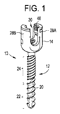
[05] FIGURE 1 is a perspective view of an exemplary embodiment of a bone
anchor assembly;
[06] FIGURE 2 is a side view of the bone anchor assembly of FIGURE 1;
[07] FIGURE 3 is a side view in cross section of the bone anchor assembly of
FIGURE 1;
[08] FIGURE 4 is a side view of the bone anchor of the bone anchor assembly
FIGURE 1;
[09] FIGURE 5 is a cross sectional view of the distal threaded section of the
bone
anchor of the bone anchor assembly FIGURE 1; and
[10] FIGURE 6 is a cross sectional view of the proximal threaded section of
the
bone anchor of the bone anchor assembly FIGURE 1.
Detail Description of Exemplary Embodiments
[11] Certain exemplary embodiments will now be described to provide an overall
understanding of the principles of the structure, function, manufacture, and
use of the
devices and methods disclosed herein. One or more examples of these
embodiments
are illustrated in the accompanying drawings. Those of ordinary skill in the
art will
understand that the devices and methods specifically described herein and
illustrated
CA 02799758 2012-11-16
WO 2011/146593 PCT/US2011/036966
3
in the accompanying drawings are non-limiting exemplary embodiments and that
the
scope of the present invention is defined solely by the claims. The features
illustrated
or described in connection with one exemplary embodiment may be combined with
the features of other embodiments. Such modifications and variations are
intended to
be included within the scope of the present invention.
[12] The articles "a" and "an" are used herein to refer to one or to more than
one
(i.e. to at least one) of the grammatical object of the article. By way of
example, "an
element" means one element or more than one element.
[13] The terms "comprise," "include," and "have," and the derivatives thereof,
are
used herein interchangeably as comprehensive, open-ended terms. For example,
use
of "comprising," "including," or "having" means that whatever element is
comprised,
had, or included, is not the only element encompassed by the subject of the
clause that
contains the verb.
[14] FIGURES 1-3 illustrate an exemplary embodiment of a bone anchor assembly
including a bone anchor 12, a receiver member 14 for receiving a spinal
fixation
element, such as a spinal rod, to be coupled to the bone anchor 12, and a
closure
mechanism 16 to capture a spinal fixation element within the receiver member
14 and
fix the spinal fixation element with respect to the receiver member 14. The
bone
anchor 12 includes a proximal head 18 and a distal shaft 20 configured to
engage
bone. The distal shaft 20 has a distal threaded section 22 and a proximal
threaded
section 24. The distal threaded section 22 may have a first pitch and a first
number of
thread starts and the proximal threaded section 24 may have a second pitch
less than
the first pitch and a second number of thread starts greater than the first
number of
thread starts. The distal threaded section 22 and the proximal threaded
section 24
may have a constant lead. The receiver member 14 has a proximal end 26 having
a
pair of spaced apart arms 28A, 28B defining a recess 30 therebetween and a
distal end
32 having a distal end surface 34 defining opening through which at least a
portion of
the bone anchor 12 extends. The closure mechanism 16 may be positionable
between
and may engage the arms 28A, 28B to capture a spinal fixation element within
the
receiver member 14 and fix the spinal fixation element with respect to the
receiver
member 14.
CA 02799758 2012-11-16
WO 2011/146593 PCT/US2011/036966
4
[15] Continuing to refer to FIGURES 1-3 and also referring to FIGURE 4, the
proximal head 16 of the bone anchor 12 in the exemplary embodiment is
generally in
the shape of a truncated sphere having a planar proximal surface 36 and an
approximately spherically shaped distal surface 38. The exemplary bone anchor
assembly is a polyaxial bone screw designed for posterior implantation in the
pedicle
or lateral mass of a vertebra. In this regards, the proximal head 18 of the
bone anchor
12 engages the distal end 32 of the receiver member 14 in a ball and socket
like
arrangement in which the proximal head 18, and thus the distal shaft 20, can
pivot
relative to the receiver member 14. The distal surface 38 of the proximal head
18 of
the bone anchor 12 and the mating surface of the within the distal end 32 of
the
receiver member 14 may have any shape that facilitates this ball and socket
like
arrangement, including, for example, spherical (as illustrated), toroidal,
conical,
frustoconical, and any combinations of these shapes.
[16] The distal shaft 20 of the bone anchor 12 may be cannulated, having a
central
passage or cannula 40 extending the length of the bone anchor 12 to facilitate
delivery
of the bone anchor 12 over a guide wire in, for example, minimally invasive
procedures. The distal shaft 20 may also include one or more side wall
openings 42
or fenestrations that communicate with the cannula 40 to permit bone in-growth
or to
permit the dispensing of bone cement or other materials through the bone
anchor 10.
The side wall openings 42 extend radially from the cannula 40 through the side
wall
of the distal shaft 20. Exemplary systems for delivering bone cement to the
bone
anchor assembly 10 and alternative bone anchor configurations for facilitating
cement
delivery are described in U.S. Patent Application Publication No.
2010/0114174,
which is hereby incorporated herein by reference. The distal shaft 20 of the
bone
anchor 12 may also be coated with materials to permit bone growth, such as,
for
example, hydroxyl apatite, and the bone anchor assembly 10 may be coated all
or in-
part with anti-infective materials, such as, for example, tryclosan.
[17] Continuing to refer to FIGURES 1-3, the proximal end 26 of the receiver
member 14 of the exemplary bone anchor assembly 10 includes a pair of spaced
apart
arms 28A, 28B defining the U-shaped recess 30 therebetween for receiving a
spinal
fixation element. The distal end 32 of the receiver member 14 is generally
cylindrical
in shape and includes distal end surface 34 which is generally annular in
shape
CA 02799758 2012-11-16
WO 2011/146593 PCT/US2011/036966
defining a circular opening through which at least a portion of the bone
anchor 12
extends. For example, the distal shaft 20 of the bone anchor 12 may extend
through
the opening. Each arm 28A, 28B of the proximal end 26 of the receiver member
14
extends from the distal end 32 of the receiver member 14 to a free end. The
outer
surface of each arm 28A, 28B may include a feature, such as a recess, dimple,
notch,
projection, or the like, to facilitate connection of the receiver member 14
and, thus,
the bone anchor assembly 10, to instruments. In the exemplary embodiment, for
example, the outer surface of each arm 28A, 28B includes an arcuate groove
44A,
44BA at the respective free end of the arms. Such grooves are described in
more
detail in U. S. Patent No. 7,179,261, which is incorporated herein by
reference.
[18] The proximal end 26 of the receiving member 14 may be configured to
receive
a closure mechanism, such as internal set screw (closure mechanism 16) or an
external cap or nut. For example, the interior surface of each arm 28A, 28B
may
include a feature, such as a recess, dimple, notch, projection, thread or the
like, to
facilitate connection of the closure mechanism 16 to the receiver member 14.
In the
exemplary embodiment, for example, the interior surface of each arm 28A, 28B
includes an internal thread 46 on the interior surface of each arm 28A, 28B
for
engaging the closure mechanism 16. In the exemplary embodiment, the thread
starts
at the free, proximal end and extends distally along at least a portion of the
length of
the arms 28A, 28B.
[19] The closure mechanism 16 in the exemplary embodiment is an internal set
screw having an external thread that engages the internal thread of the
receiver
member to capture a spinal fixation element within the recess 30 of the
receiver
member and, when fully tightened, to fix the spinal fixation element relative
to the
receiver member 14. Alternatively, the closure mechanism may be dual closure
mechanism having an inner and an outer set screw, such as, for example, the
Expedium Dual Innie Polyaxial Screw available from DePuy Spine, Inc. of
Raynham,
MA. In addition, the closure mechanism may be a non-threaded twist in cap,
such as,
for example, the Monarch Typhoon Cap available from DePuy Spine, Inc. of
Raynham, MA, and described in U.S. Patent No. 6,755,829, incorporated herein
by
reference.
CA 02799758 2012-11-16
WO 2011/146593 PCT/US2011/036966
6
[20] The exemplary bone anchor assembly 10 may be used with a spinal fixation
element such as a rigid spinal rod. The spinal rod may be constructed
titanium,
titanium alloys, stainless steel, cobalt chrome, PEEK, or other materials
suitable for
rigid fixation. Alternatively, the spinal fixation element may be a dynamic
stabilization member that allows controlled mobility between the instrumented
vertebrae.
[21] The exemplary bone anchor assembly is a rigid polyaxial screw in which
the
bone anchor 12 is fixed, rather than mobile, when the spinal fixation element
is fixed
to the receiver member 14 of the bone anchor assembly. The spinal fixation
element
may either directly contact the proximal head 18 of the bone anchor 12 or may
contact
an intermediate element, e.g., a compression member 100, interposed between
the
spinal fixation element and the proximal head 18 of the bone anchor 12 to
compress
the distal outer surface of the proximal head 18 into direct, fixed engagement
with the
distal inner surface of the receiver member 18 when the spinal fixation
element is
fixed to the receiver member 16 of the bone anchor assembly by the closure
mechanism. In alternative embodiments, the bone anchor assembly may be a
mobile
screw in which the proximal head 18 of the bone anchor 12 can move relative to
the
receiver member 14 when the spinal fixation element is fixed to the receiver
member
14. An exemplary mobile polyaxial screw is described is U.S. Patent
Application No.
12/580,777, filed October 16, 2009, which is hereby incorporated herein by
reference.
Alternatively, the bone anchor assembly may be a monoaxial screw, a favored
angle
screw or a uniplanar screw.
[22] The threaded distal section 22 and the threaded proximal section 24 of
the
distal shaft of the bone anchor 12 may be configured to increase fixation of
the bone
anchor assembly 10 in bone. For a bone anchor assembly designed to be
implanted
through the pedicle of a vertebra, for example, the threaded distal section 22
may be
configured to engage the cancellous bone in the anterior vertebral body of the
vertebra
and the threaded proximal section 24 may be configured to engage the cortical
bone
of the pedicle of the vertebra. In particular, the threaded distal section 22
may have a
pitch that is greater than (i.e., more coarse) the pitch of the proximal
section 24. To
facilitate insertion of the bone anchor 12 into the vertebra and prevent
stripping of the
pedicle wall, the distal shaft 20, both the threaded distal section 22 and
threaded
proximal section 24, can have a constant thread lead. The lead of a thread is
the
CA 02799758 2012-11-16
WO 2011/146593 PCT/US2011/036966
7
distance the distal shaft 20 travels in a direction parallel to the
longitudinal axis 50 of
the shaft when the distal shaft 20 is rotated one turn (360 ). The lead of a
thread is
equal to the number of thread starts multiplied by the pitch of the thread. As
the
threaded distal section 22 and the threaded proximal section 24 have different
pitches,
the threaded distal section 22 and the threaded proximal section 24 must have
a
different number of thread starts in order to have a constant or equal lead.
In the
exemplary polyaxial bone anchor assembly 10, for example, the lead of the
distal
shaft 20 is 6mm, the pitch of distal threaded section 22 is 3mm and the distal
threaded
section 22 has two thread starts (i.e., the distal threaded section 22 is dual
threaded)
and the pitch of proximal threaded section 24 is 1.5mm and the proximal
threaded
section 24 has four thread starts (i.e., the proximal threaded section 24 is
quad
threaded). FIGURE 5 is a cross section of the distal threaded section 22 and
illustrates the two thread crests 52A and 52B of the dual thread of the distal
threaded
section 22. FIGURE 6 is a cross section of the proximal threaded section 24
and
illustrates the four thread crests 54A-54D of the quad thread of the proximal
threaded
section 24. Table 1 provides a summary for the exemplary bone anchor assembly
10:
Table 1
Pitch Starts Lead
Distal Threaded Section 22 3 mm 2 6mm
Proximal Threaded Section 24 1.5mm 4 6mm
[23] The lead of the threaded distal section 22 and the threaded proximal
section 24
can vary depending on, for example, the type of bone anchor assembly (e.g.,
polyaxial, monoaxial, uniplanar) and the vertebra or other bone in which the
assembly
is to be implanted. For polyaxial bone anchors designed to be inserted through
the
pedicle of a lumbar or thoracic vertebra, for example, the lead may be from
4mm to
8mm and the pitch of the distal threaded section 22 may be from 2mm to 4mm,
and
the pitch of the proximal threaded section 24 may be from 1mm to 3mm. In
monoaxial screws, for example, the lead may be 2mm to 4mm.
[24] The axial length (i.e., the length in a direction parallel to the
longitudinal axis
50) of the proximal threaded section 24 of the distal shaft 20 can vary
depending on
CA 02799758 2012-11-16
WO 2011/146593 PCT/US2011/036966
8
the vertebra or other bone in which the assembly is to be implanted and may be
selected to correspond to the length of bone the proximal threaded section 24
will
engage. For bone anchors designed to be inserted through the pedicle of a
lumbar or
thoracic vertebra, the axial length of the proximal threaded section 24 may be
selected
to approximate the length of the pedicle including the distance from the
posterior
surface of the vertebra through the pedicle to the junction of the pedicle and
the
anterior vertebral body of the vertebra. In such bone anchors, the axial
length Ll of
the proximal threaded section 24 may be between 14mm and 26mm and preferably
is
20mm. The axial length of the distal shaft 20 may also vary depending on the
bone in
which the bone anchor 12 is to be inserted. For bone anchors designed to be
inserted
through the pedicle of a lumbar or thoracic vertebra, the axial length L2 of
the distal
shaft 20 may be between 20mm and 100mm. For bone anchors designed to be
inserted through the iliac, the axial length L2 of the distal shaft 20 may be
between
60mm and 150mm.
[25] The major diameter and the minor diameter of the distal threaded section
22
and the proximal threaded section 24 may be selected based on the bone in
which the
bone anchor 12 is to be inserted. For bone anchors designed to be inserted
through
the pedicle of a lumbar or thoracic vertebra (such as the exemplary bone
anchor 12),
for example, the major diameter of the distal threaded section 22 and the
proximal
threaded section 24 may be between 4mm and 10mm. In the exemplary embodiment,
the major diameter of the distal threaded section 22 and the major diameter of
the
proximal threaded section 24 are equal and constant over the axial length of
the distal
threaded section 22 and the proximal threaded section 24. In the exemplary
embodiment, the minor diameter of the proximal threaded section 24 is greater
than
the minor diameter of the distal threaded section 22. The increased minor
diameter of
the proximal threaded section 24 provides reduced thread depth for the
proximal
threaded section 24 which increases bone purchase by compressing the bone of
the
pedicle of the vertebra. The minor diameter of the distal threaded section 22
is
constant over the axial length of the distal threaded section 22 and the minor
diameter
of the proximal threaded section 24 is constant over the axial length of the
proximal
threaded section 24. The minor diameter may increase step wise or gradually
from
the distal threaded section 22 to the proximal threaded section 24. Table 2
provides
CA 02799758 2012-11-16
WO 2011/146593 PCT/US2011/036966
9
exemplary major and minor diameters for the distal threaded section 22 and
proximal
threaded section 24.
[26] Table 2
Major Distal Threaded Proximal Threaded Minor
Diameter (mm) Section Minor Section Minor Diameter Diameter
Diameter (mm) (mm) Increase
(mm)
4.425 3.075 3.425 0.35
4.9 3.66 4.03 0.37
5.89 4.06 4.31 0.25
6.85 4.47 5 0.53
7.85 5.05 6 0.95
8.85 6.05 7 0.95
9.85 7.05 8 0.95
10.85 8.05 9 0.95
11.85 9.05 10 0.95
[27] In alternative embodiments, the minor diameter of the distal threaded
section
22 and the minor diameter of the proximal threaded section 24 may be equal and
constant over the axial length of the distal threaded section 22 and the minor
diameter
of the proximal threaded section 24.
[28] In alternative embodiments, the major diameter of the proximal threaded
section 24 may be greater than the major diameter of the distal threaded
section 22.
The major diameter may increase step wise or gradually from the distal
threaded
section 22 to the proximal threaded section 24.
[29] While the devices and methods of the present invention have been
particularly
shown and described with reference to the exemplary embodiments thereof, those
of
ordinary skill in the art will understand that various changes may be made in
the form
and details herein without departing from the spirit and scope of the present
invention.
Those of ordinary skill in the art will recognize or be able to ascertain many
equivalents to the exemplary embodiments described specifically herein by
using no
more than routine experimentation. Such equivalents are intended to be
encompassed
by the scope of the present invention and the appended claims.