Note : Les descriptions sont présentées dans la langue officielle dans laquelle elles ont été soumises.
CA 02799810 2012-12-20
247468
CONNECTOR ASSEMBLY AND METHOD OF
FABRICATING THE SAME
BACKGROUND OF THE INVENTION
[0001] The field of this disclosure relates generally to connector
assemblies and, more particularly, to a connector assembly for connecting a
wire to a
device.
[0002] Many known systems (e.g., automobiles, watercraft, aircraft,
spacecraft, etc.) utilize a plurality of devices (e.g., electro-mechanical
devices such as
motors, pumps, and sensors). At least some of these known systems utilize
harnesses to
route bundles of wires through the system in an organized manner that enables
providing
electrical power to, or communication with, the devices with minimal
interference
between the devices and the wires. It would be useful to provide an improved
interface
between the wires and the devices to reduce costs associated with
manufacturing,
installing, and operating the systems.
BRIEF DESCRIPTION OF THE INVENTION
[0003] In one aspect, a method of fabricating a connector assembly for
connecting a wire to a device of a gas turbine engine is provided. The method
includes
providing a wire having a termination and providing a first shell having a
first proximal
end, a first distal end, and a first passage extending from the first proximal
end to the first
distal end. The method further includes coupling the first shell to the wire
such that the
wire extends into the first passage through the first proximal end, wherein
the first shell is
displaceable along the wire relative to the termination.
[0004] In another aspect, a connector assembly for connecting a
termination of a wire to a device of a gas turbine engine is provided. The
connector
-1-
CA 02799810 2012-12-20
247408
assembly includes a first grommet structure configured to be coupled to the
wire and a first
shell having a first proximal end, a first distal end, and a first passage
extending from the
first proximal end to the first distal end. The first shell is configured to
be coupled to the
wire such that the wire extends into the first passage through the first
proximal end. The
first shell is also configured to be displaceable along the wire relative to
the termination
and the first grommet structure from a first position in which the first
grommet structure is
disposed within the first passage to a second position in which the first
grommet structure
is exposed outside of the first passage.
[0005] In another aspect, a gas turbine engine is provided. The gas
turbine engine includes a device, a wire having a termination, and a connector
assembly
operatively coupling the termination to the device. The connector assembly
includes a first
shell having a first proximal end, a first distal end, and a first passage
extending from the
first proximal end to the first distal end. The first shell is coupled to the
wire such that the
wire extends into the first passage through the first proximal end, and the
first shell is
displaceable along the wire relative to the termination.
BRIEF DESCRIPTION OF THE DRAWINGS
[0006] Figure 1 is a schematic illustration of a gas turbine engine;
[0007] Figure 2 is a schematic illustration of an electrical or
communication system of the gas turbine engine shown in Figure 1;
[0008] Figure 3 is a schematic cross-sectional illustration of the system
shown in Figure 2 taken along line 3-3;
[0009] Figure 4 is a perspective view of a portion of the system shown in
Figure 2 (taken within Portion 4) illustrating a device coupled to a wire via
a connector
assembly;
[0010] Figure 5 is a side view of the connector assembly shown in
Figure 4;
-2-
CA 02799810 2012-12-20
247408
[0011] Figure 6 is a cross-sectional view of the connector assembly
shown in Figure 4 and taken along line 6-6 of Figure 5;
[0012] Figure 7 is a partial perspective view of the connector assembly
shown in Figure 4 in an assembled state;
[0013] Figure 8 is a partial perspective view of the connector assembly
shown in Figure 4 in a first disassembled state; and
[0014] Figure 9 is a partial perspective view of the connector assembly
shown in Figure 4 in a second disassembled state.
DETAILED DESCRIPTION OF THE INVENTION
[0015] The following detailed description sets forth a connector
assembly and a method of fabricating the same by way of example and not by way
of
limitation. The description should clearly enable one of ordinary skill in the
art to make
and use the connector assembly, and the description sets forth several
embodiments,
adaptations, variations, alternatives, and uses of the connector assembly,
including what
is presently believed to be the best mode thereof. The connector assembly is
described
herein as being applied to a preferred embodiment, namely an electrical
harness for a gas
turbine engine. However, it is contemplated that the connector assembly and
the method
of fabricating the same have general application in a broad range of systems
and/or a
variety of other commercial, industrial, and/or consumer applications.
[0016] Figure 1 is a schematic illustration of an exemplary gas turbine
engine 100 including a fan system 102, a compressor system 104, a combustion
system
106, a high pressure turbine system 108, and a low pressure turbine system
110. During
operation, ambient air is directed through fan system 102 into compressor
system 104, in
which the ambient air is compressed and directed into combustion system 106.
In
combustion system 106, the compressed air is mixed with fuel and ignited to
generate
combustion gases that are directed through high pressure turbine system 108
and low
-3-
CA 02799810 2012-12-20
247468
pressure turbine system 110. The combustion gases are subsequently exhausted
from gas
turbine engine 100 via an exhaust system 112. In other embodiments, gas
turbine engine
100 may include any suitable number of fan systems, compressor systems,
combustion
systems, and/or turbine systems configured in any suitable manner.
[0017] Figure 2 is a schematic illustration of an electrical or
communication system 200 of gas turbine engine 100, and Figure 3 is a
schematic cross-
sectional illustration of system 200 taken along line 3-3. In the exemplary
embodiment,
system 200 includes a harness 202, a plurality of devices 204 (e.g.,
electrical devices such
as motors, pumps, sensors, etc.) coupled to ends 206 of harness 202, and a
plurality of
mounting devices 208 coupled at intermediate locations along harness 202
between ends
206. System 200 also includes an electrical or communication source 209 (e.g.,
a
generator or a control unit) for providing electrical power to, or
communication with,
devices 204 via harness 202. Harness 202 includes at least one wire 210 that
may be
disposed within a covering 212 (e.g., a layer of a braided material) to
facilitate protecting
wire 210 from chaffing and/or electromagnetic interference (EMI). Harness 202
has a
main segment 214 and a plurality of breakout segments 216 extending from main
segment 214, thereby enabling wire 210 to be more easily routed to devices
204.
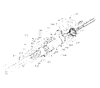
[0018] Figure 4 is a perspective view of a portion of system 200 (taken
within Portion 4 of Figure 2) illustrating one device 204 coupled to wires 210
via a
connector assembly 300. Figure 5 is a side view of connector assembly 300, and
Figure 6
is a cross-sectional view of connector assembly 300 taken along line 6-6 of
Figure 5. In
the exemplary embodiment, connector assembly 300 includes a first shell 302, a
second
shell 304, and a wire connection 306 housed within first and second shells
302, 304.
[0019] In the exemplary embodiment, first shell 302 includes a generally
cylindrical body 308 and an annular coupling segment 310. Body 308 has a
proximal end
312, a distal end 314, a radially inner surface 316, and a radially outer
surface 318. Distal
end 314 has a plurality of teeth 320, and radially inner surface 316 extends
from proximal
end 312 to distal end 314 to define a passage 322. Passage 322 has a proximal
region 324
-4-
CA 02799810 2012-12-20
247408
near proximal end 312 and a distal region 326 near distal end 314, and
proximal region
324 is narrower than distal region 326 such that a lip 328 is defined between
proximal
region 324 and distal region 326. Coupling segment 310 is integrally formed
with, and
extends distally from, body 308 and includes a threaded inner surface 330. In
one
embodiment, coupling segment 310 and body 308 are integrally formed together
from a
metallic material (e.g., a stainless steel material). In other embodiments,
first shell 302
may have any suitable configuration that facilitates enabling connector
assembly 300 to
function as described herein (e.g., coupling segment 310 may be rotatable
relative to
body 308 to facilitate threadably coupling first shell 302 to second shell 304
via threaded
inner surface 330 as described below).
[0020] In the exemplary embodiment, second shell 304 is generally
cylindrical and has a proximal end 332, a distal end 334, a radially inner
surface 336, and
a radially outer surface 338. Radially inner surface 336 extends from proximal
end 332
to distal end 334 to define a passage 340. Second shell 304 is fabricated from
a metallic
material (e.g., a stainless steel material) and is configured to be coupled to
(e.g., welded
to) a housing 205 of device 204 at proximal end 332. Outer surface 338 is
threaded near
distal end 334, and distal end 334 has a plurality of teeth 342 that are
configured to mate
with (e.g., be interdigitated with) teeth 320 of first shell 302. In other
embodiments,
second shell 304 may have any suitable shape, may be fabricated from any
suitable
material, and may be coupled to housing 205 of device 204 in any suitable
manner (e.g.,
second shell 304 may be fabricated from a plastic material and may be
integrally formed
with housing 205 in some embodiments). Additionally, second shell 304 may have
any
suitable configuration near proximal end 332 and/or distal end 334 that
facilitates
coupling second shell 304 to first shell 302 and device 204 in the manner
described
herein. As used herein, references to first shell 302 and/or second shell 304
in terms of
orientation within (e.g., references such as first shell 302 or second shell
304 has an
'proximal end' or an 'distal end') are intended to mean that first shell 302
and second
shell 304 are configured to be oriented in such a manner when connector
assembly 300 is
at least partially assembled as described herein, and such references to
orientation are not
-5-
CA 02799810 2012-12-20
2474e8
intended to limit the scope of this disclosure to only those connector
assemblies that are
actually assembled. Rather, this disclosure is intended to apply to connector
assemblies
in general, whether assembled or not.
[0021] Wire connection 306 includes at least one wire 210, at least one
contact 344 (e.g., a pin), and a support assembly 346. In the exemplary
embodiment,
wire connection 306 includes four contacts 344 and four corresponding wires
210. In
other embodiments, wire connection 306 may have any suitable number of
contacts 344
and wires 210. In the exemplary embodiment, contacts 344 are operatively
coupled to
device 204 (e.g., to provide power to device 204 or to provide communication
with
device 204) and extend into passage 340 via proximal end 332 of second shell
304. Each
wire 210 includes a termination 211 having a retainer ring 213 and a socket
contact 215,
and wires 210 extend into passage 322 via proximal end 312 of first shell 302.
In other
embodiments, contacts 344 and wires 210 may be configured in any suitable
manner that
facilitates enabling connector assembly 300 to function as described herein.
[0022] In the exemplary embodiment, support assembly 346 includes a
ceramic structure 348, a rigid dielectric structure 350, a first rigid grommet
structure 352,
and a second rigid grommet structure 354 (e.g., a sealing grommet structure).
Ceramic
structure 348, dielectric structure 350, and second grommet structure 354 are
fixedly
coupled within second shell 304 (e.g., via an adhesive) such that ceramic
structure 348 is
adjacent proximal end 332, second grommet structure 354 is adjacent distal end
334, and
dielectric structure 350 is disposed between ceramic structure 348 and second
grommet
structure 354. At least one through-port 356 is defined through ceramic
structure 348,
dielectric structure 350, and second grommet structure 354 and extends
generally from
distal end 334 to proximal end 332. In the exemplary embodiment, four through-
ports
356 are provided to correspond with four wires 210 and four contacts 344. In
other
embodiments, any suitable number of through-ports 356 may be provided. In the
exemplary embodiment, a retention mechanism (e.g., a tapered retainer sleeve
358) lines
a portion of each through-port 356 in dielectric structure 350. Alternatively,
support
-6-
CA 02799810 2012-12-20
247408
assembly 346 may be configured with any suitable number of ceramic structures,
dielectric structures, and/or second grommet structures arranged in any
suitable manner
that facilitates enabling connector assembly 300 to function as described
herein.
[0023] In the exemplary embodiment, first grommet structure 352 is
coupled to, and is displaceable along, wires 210 via a plurality of through-
ports 360
defined in first grommet structure 352. First shell 302 is also displaceable
along wires
210. In this manner, first grommet structure 352 and first shell 302 are
displaceable
relative to one another along wires 210. Because first grommet structure 352
is
configured to be disposed within distal region 326 of passage 322 and is sized
to be larger
than proximal region 324 of passage 322, first grommet structure 352
facilitates
preventing first shell 302 from being removed from wires 210 because first
grommet
structure 352 would contact lip 328 and provide a limit stop for displacing
first shell 302
toward terminations 211. In other embodiments, wires 210, first shell 302, and
first
grommet structure 352 may be configured in any suitable manner that
facilitates enabling
connector assembly 300 to function as described herein.
[0024] Figures 7, 8, and 9 are partial perspective views of connector
assembly 300 in an assembled state, a first disassembled state, and a second
disassembled
state, respectively. Referring to Figure 7, in the assembled state of
connector assembly
300, second shell 304 is coupled (e.g., welded) to housing 205 of device 204
such that
contacts 344 extend into passage 340 via proximal end 332 of second shell 304.
Ceramic
structure 348, dielectric structure 350, and second grommet structure 354 are
fixedly
retained within passage 340 (e.g., via adhesive) such that contacts 344 extend
into
dielectric structure 350 via through-ports 356. Additionally, first shell 302
is coupled to
second shell 304 such that teeth 320 of distal end 314 mate with teeth 342 of
distal end
334 and such that threaded inner surface 330 of coupling segment 310
interfaces with
threaded outer surface 338 of second shell 304. Wires 210 extend through
passage 322 of
first shell 302 (e.g., into proximal end 312 and out of distal end 314) via
through-ports
360 of first grommet structure 352. Wires 210 also extend into passage 340 of
second
-7-
CA 02799810 2012-12-20
247408
shell 304 via distal end 334 such that wires extend through second grommet
structure 354
and into dielectric structure 350 via through-ports 356.
[0025] In this manner, socket contact 215 of each wire 210 receives one
associated contact 344 in order to couple (e.g., electrically couple or
communicatively
couple) wires 210 to device 204. To facilitate maintaining the coupling
between socket
contacts 215 and contacts 344, retainer rings 213 of terminations 211 are
inserted into
corresponding retainer sleeves 358, and the tapered shape of retainer sleeves
358 restricts
uncoupling of socket contacts 215 from contacts 344. Because first grommet
structure
352 and second grommet structure 354 are substantially aligned (i.e., through-
ports 360,
356 are substantially aligned), wires 210 are maintained in a substantially
linear, parallel
orientation as they extend from first grommet structure 352 into second
grommet
structure 354, thereby spacing wires 210 relative to one another and relative
to shells 302,
304 to minimize interference and chaffing.
[0026] Referring now to Figures 8 and 9, to disassemble connector
assembly 300 (i.e., to uncouple wires 210 from device 204), coupling segment
310 of
first shell 302 is unthreaded from second shell 304, and first shell 302 is
displaced toward
(and, in some embodiments, over) covering 212 along wires 210 from a first
position
(Fig. 7) in which first grommet structure 352 is disposed within passage 322
to a second
position (Fig. 8) in which first grommet structure 352 is exposed outside of
passage 322.
With first grommet structure 352 exposed outside of passage 322, first grommet
structure
352 is displaced toward covering 212 along wires 210 to provide sufficient
spacing
between first grommet structure 352 and second grommet structure 354 to enable
removal of wires 210 from second shell 304 (Fig. 9). To remove wires 210 from
second
shell 304, retainer rings 213 are uncoupled from retainer sleeves 358, socket
contacts 215
are uncoupled from contacts 344, and wires 210 are pulled out of through-ports
356 (e.g.,
tools may be inserted into through-ports 356 to grip and uncouple terminations
211).
With socket contacts 215 uncoupled from contacts 344, device 204 is no longer
electrically or communicatively coupled to wires 210, thereby better enabling
device 204
-8-
CA 02799810 2012-12-20
247408
(e.g., the sensor device) and/or harness 202 (e.g., wires 210) to be repaired
or replaced in
the field. By suitably reversing the aforementioned steps, connector assembly
300 may
be reassembled after the desired repair or replacement.
[0027] The methods and systems described herein facilitate enabling a
device to be coupled and uncoupled from a wire. The methods and systems
described
herein also facilitate exposing wire terminations for repair or replacement
when a device
is uncoupled from the wire. The methods and systems described herein further
facilitate
reducing the number of components associated with a connector assembly,
thereby
reducing the raw materials used to fabricate the connector assembly and
reducing space
and weight of the connector assembly. The methods and systems described herein
therefore facilitate simplifying the interface between a wire and an
associated device to
reduce costs associated with manufacturing, installing, and operating a
system.
[0028] Exemplary embodiments of a connector assembly and a method
of fabricating the same are described above in detail. The methods and systems
are not
limited to the specific embodiments described herein, but rather, components
of the
methods and systems may be utilized independently and separately from other
components described herein. For example, the methods and systems described
herein
may have other industrial and/or consumer applications and are not limited to
practice
with only electrical harnesses of gas turbine engines as described herein.
Rather, the
present invention can be implemented and utilized in connection with many
other
industries.
[0029] While the invention has been described in terms of various
specific embodiments, those skilled in the art will recognize that the
invention can be
practiced with modification within the spirit and scope of the claims.
-9-