Note : Les descriptions sont présentées dans la langue officielle dans laquelle elles ont été soumises.
CA 02800192 2012-11-21
WO 2011/149579 PCT/US2011/027969
PRELOADED DUAL-SPRING ASSEMBLY
INVENTOR
Charles F. Pepka
FIELD OF THE INVENTION
[0001] This invention relates generally to a dual-spring assembly for varying
the
combined resultant spring rate of the assembly as the dual springs are
compressed, and more
specifically to a shock absorber unit having the dual-spring assembly with a
system for adjusting
an amount of preload in one or both of the springs.
BACKGROUND OF THE INVENTION
[0002] Conventional shock absorbers of the type used in vehicles, such as
automobiles,
typically include a shock damper and a compression spring. At least two
parameters considered
when designing shock absorbers include the weight of the vehicle and the
probable range of
driving speeds. Typically, the damping coefficient of the shock damper and the
spring constant
of a compression spring are often fixed and thus not adjustable once the shock
absorber has been
fully assembled. However, one or more of the following may affect the
efficiency and operation
of the shock absorber: the vehicle weight, the range of driving speeds, the
terrain (e.g., uneven or
rough terrain), steering requirements and the environment. While it is
appreciated that a stiffer
spring (i.e., larger spring constant or spring rate) permits restoration of
the spring to its original
state quicker and easier after a deflection, it is also appreciated that a
softer spring (i.e., smaller
or lower spring constant or spring rate) absorbs energy more easily. Over the
years, much effort
-1-
CA 02800192 2012-11-21
WO 2011/149579 PCT/US2011/027969
has been devoted to researching spring constants in an attempt to achieve
higher stability and
comfort when a vehicle is driven over uneven roads, at high speeds, or is
subjected to harsh
steering maneuvers. As a consequence, many conventional shock absorbers have a
single
compression spring with a spring constant selected to handle "average" road or
terrain
conditions, which are those conditions assumed to be encountered during use of
a particular
vehicle or type of vehicle.
[0003] Some conventional suspension or coil spring systems are described in
U.S.
Patent Nos. 5,263,695 and 7,350,774 and in U.S. Patent Publication Nos.
2002/0038929 and
2008/0099968. By way of example, the conventional spring system described in
U.S. Patent No. 5,263,695 attempts to achieve a good level of comfort and a
good level of
behavior using two springs mounted in series around a shock absorber. The
conventional spring
system described in U.S. Patent No. 7,350,774 includes a mechanical spring
combination having
a large travel, with an initial low spring rate during an initial range of
compression and
developing a high spring force through a second, but shorter range of
compression. However,
typical dual-spring shock absorber arrangements are used as simply a
progressive combination to
avoid movement through the entire stroke of the springs in a large impact
scenario.
SUMMARY OF THE INVENTION
[0004] The present invention relates to dual-spring assembly that may be
employed in
cooperation with a damper unit to form a shock absorber. The spring rate of at
least one of the
springs is adjustable with a preload mechanism, which in turn is movable
relative to the damper
unit. Further, the dual-spring assembly includes at least two compression
springs arranged in
series and each having selected spring rates. The first spring primarily
absorbs the energy of
applied loads that are below a first amplitude of applied load. Once the
applied loads exceed the
first amplitude of applied load and once an amount of preload in the spring
with the second
spring rate is overcome, the dual-spring assembly operates with a lower
"effective" spring rate to
absorb the energy of applied loads that exceed the first amplitude of applied
load (e.g., high
impact loads, such as hitting a curb with a front wheel).
[0005] In accordance with an aspect of the invention, a dual-spring assembly
for a
shock absorber includes a first compression spring having a first spring rate;
and a second
-2-
CA 02800192 2012-11-21
WO 2011/149579 PCT/US2011/027969
compression spring having a second spring rate that may be lower, higher, or
the same as the
first spring rate, the second compression spring having an amount of preload,
the first and second
compression springs arranged in series and operable to have an effective
spring rate for
absorbing energy from an applied load after the applied load is large enough
to overcome the
amount of preload in the second compression spring. The combined effective
spring rate of the
springs, once the preload is overcome (i.e., both springs engaged) is lower
than the spring rate of
the first spring. This lower effective spring rate allows the vehicle to
better deal with high
amplitude impact occurrences that would otherwise be very disruptive to a
completely
progressive suspension with a high spring rate.
[0006] In accordance with another aspect of the invention, a shock absorber
includes a
piston-cylinder assembly having at least one piston movable within a cylinder
at least partially
filled with a fluid; and a dual-spring assembly having first and second
compression springs
arranged in series, the first compression spring having a first mean coil
diameter relative to a first
coil axis and a first spring rate, and the second compression spring having a
second mean coil
diameter relative to a second coil axis aligned substantially parallel with
the first coil axis, the
second compression spring includes a second spring rate, the second
compression spring further
includes an amount of preload such that it compresses only after the first
spring reaches a certain
load, wherein the first and second compression springs operate with a lower
effective spring rate
than that of the first spring alone for absorbing energy from an applied load
after the applied load
exceeds a load sufficient to overcome the amount of preload in the second
compression spring.
[0007] In accordance with yet another aspect of the invention, a method of
absorbing
applied loads with a dual-spring assembly includes the steps of (1) arranging
first and second
compression springs in series about the body of a shock absorber; (2)
absorbing energy from a
first applied load primarily with the first compression spring when the first
applied load is below
a predetermined amplitude of applied load; and (3) absorbing energy from a
second applied load
primarily with the first and second compression springs operating in series
when the second
applied load is above the predetermined amplitude of applied load and after
the second applied
load overcomes an amount of preload in the second compression spring. The
combined spring
rate of the first and second springs being lower than that of the first
spring.
-3-
CA 02800192 2012-11-21
WO 2011/149579 PCT/US2011/027969
BRIEF DESCRIPTION OF THE DRAWINGS
[0008] Preferred and alternative embodiments of the present invention are
described in
detail below with reference to the following drawings:
[0009] FIGURE 1 is schematic view of a shock absorber having a dual spring
assembly
that is adjustable by a preload system according to an embodiment of the
present invention;
[0010] FIGURE 2 is cross-sectional view of the dual-spring assembly of FIGURE
1
with the springs in free state;
[0011] FIGURE 3 is a spring rate curve for at least one of the springs of the
dual-spring
assembly of FIGURE 1;
[0012] FIGURE 4 is a spring rate curve for the dual-spring assembly of FIGURE
1
showing various regions and applied load thresholds relating to the operation
of the dual-spring
assembly according to an embodiment of the present invention; and
[0013] FIGURE 5 is a schematic view of the shock absorber and preload system
of
FIGURE 1 with stop limiters of the preload system preventing further
deflection of a lower
spring according to an embodiment of the present invention.
DETAILED DESCRIPTION OF THE PREFERRED EMBODIMENT
[0014] As will be described in further detail below, at least one embodiment
of the
invention includes a dual-spring assembly that may cooperate with a damper
unit of a shock
absorber. In addition, the shock absorber may include a preload system for
preloading at least
one of the springs. The dual springs are arranged in series. In one
embodiment, the spring with
the higher spring rate operates as the primary spring to absorb the energy
from applied loads that
are less than a desired amplitude of applied load. For loads greater than the
desired amplitude of
applied load and after the preload in the second spring has been overcome, the
springs operate
together with a lower effective spring rate to absorb high amplitude impact
loads, for example. In
another embodiment, the spring with the lower individual spring rate operates
as the primary
spring, with the higher rate spring being preloaded. However, even in this
embodiment, the
combined effective spring rate, once the preload is overcome and both springs
are engaged, is
lower than that of the primary spring. The primary spring in either case may
also have a preload.
However, the preload of the primary spring is less than that of the secondary
spring such that the
-4-
CA 02800192 2012-11-21
WO 2011/149579 PCT/US2011/027969
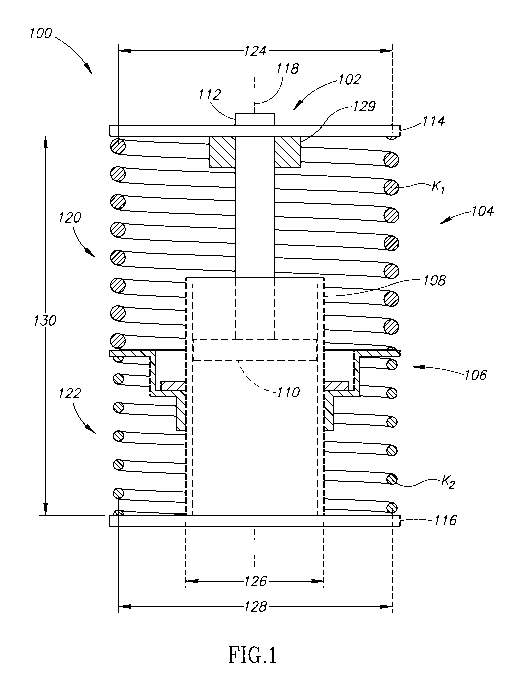
support member 114, secured to the cylinder 108. In one embodiment, the lower
support
member 116 is adjustable relative to the cylinder 108 and may be used with the
preload
system 106 to adjust the amount of preload in one or both springs of the dual-
spring
assembly 104. It is appreciated the terms "upper" and "lower' as used herein
are for reference
purposes only. Further, the terms "upper" and "lower" merely orient the reader
to the illustrated
embodiment and they do not limit the invention to any particular spatial
orientation or
configuration.
[0017] The cylinder 108 defines a cylindrical axis 118 that coincides with a
longitudinal axis of the piston rod 112. Accordingly, movement of the piston
110 occurs along a
linear direction substantially parallel to the cylindrical axis 118. In one
embodiment, the
cylinder 108 is at least partially filled with a hydraulic fluid (not shown),
such as, but not limited
to oil. In another embodiment, the cylinder 108 may take the form of a gas
charged cylinder
filled at least partially with air or nitrogen to minimize aeration of the
hydraulic fluid.
[0018] The dual-spring assembly 104 includes dual springs 120, 122 arranged in
series,
and more specifically the dual springs 120, 122 take the form of an upper
spring 120 and a lower
spring 122 according to an embodiment of the present invention. The springs
120, 122 may take
the form of helical compression springs, which may include closed and ground
end portions. The
upper spring 120 includes a first mean coil diameter 124 that is larger than a
cylinder
diameter 126. Similarly, the lower spring 122 includes a second mean coil
diameter 128, which
is also larger than the cylinder diameter 126. The first and second mean coil
diameters 124, 128
may be, but are not required to be, substantially equal. The dual springs 120,
122 may be formed
from round-wire (i.e., circular) having a desired wire diameter. In addition,
the round-wire may
take the form of steel wire and be heat treated, peened or otherwise processed
to increase the
strength and operational life of the springs 120, 122. An installed length 130
of the dual-spring
assembly 104 may achieved by preloading one or both springs 120, 122, as will
be discussed in
greater detail below. For purposes of brevity, other structural aspects and
features of
compression springs, such as helical compression springs, will not be
described in detail.
[0019] Optionally, the shock absorber 100 may include an energy absorption
device 129 attached to the upper support member 114. The energy absorption
device 129 may
-6-
CA 02800192 2012-11-21
WO 2011/149579 PCT/US2011/027969
take the form of an elastomeric bumper, sleeve, stiff spring, or collar
operable to engage the
cylinder 108 before the upper spring 120 achieves a solid height, which may be
otherwise
referred to as "stacking out". The solid height is the length of a compression
spring when under
sufficient load to bring all coils into contact with adjacent coils such that
no additional deflection
of the compression spring is possible.
[0020] FIGURE 2 shows the upper spring 120 having a first free length 130 and
the
lower spring 122 having a second free length 132. The free length is the
overall length of a
spring when it is not under an applied load. The overall free length 136 is
simply the free
lengths 130 and 132 summed together when the springs 120, 122 are arranged in
series. Further,
the upper spring 120 includes a first spring rate or spring constant, K1, and
the lower spring 122
includes a second spring rate or spring constant, K2. The spring rate is the
change or gradient
(e.g., rate of inclination or slope) of the applied load on the spring per
unit of deflection. The
spring rate for a compression spring is generally given in units of force
divided by units of
distance, for example pounds per inch (lbf/in) or Kilograms per millimeter
(Kg/mm). The spring
rate reflects the stiffness of the spring and may be measured by measuring the
spring's free
length and then adding load (e.g., weight) onto the spring. With each
increment of added load,
the change in length of the spring is measured. Linear springs maintain a
constant rate of
compression throughout their travel.
[0021] FIGURE 3 shows a non-preloaded, linear spring 138. The graphed spring
rate of
the linear spring 138 indicates that each load increment applied to the spring
results in an
incremental reduction in the length of the spring. By way of example if the
spring 138 had a
spring rate of 100 lbf/in then 100 pounds of compression force applied to the
spring 138 would
produce a reduction in the spring's length by one inch; 200 pounds of
compression force applied
to the spring 138 would produce a reduction in the spring's length by two
inches, and so on until
the spring 138 stacks out and reaches a solid height 140.
[0022] FIGURE 4 shows the spring assembly 104 in which the upper spring 120
includes a first spring rate Ki and the lower spring 122 includes a second
spring rate K2. The
upper spring may have a higher or lower spring rate than the lower spring,
depending on the
desired effective spring rate of the combination. One or both springs 120, 122
may also include
-7-
CA 02800192 2012-11-21
WO 2011/149579 PCT/US2011/027969
an amount of preload. Referring briefly back to FIGURE 1, the installed length
130 may be
achieved by inducing preload into the lower spring 122, the upper spring 120,
or into both
springs 120, 122, during or after installation. The amount of preload may be
defined in terms of
applied load or in terms of actual deflection (i.e., change in spring length).
Further, changing the
amount of pre-load does not change the spring rate, meaning one does not
obtain a stiffer spring
by adding pre-load. Once the compression spring starts to compress it will
change length in
accordance with its spring rate (for constant rate springs).
[0023] In a preferred embodiment, the first spring rate Ki of the upper spring
120 is
substantially different than the second spring rate K2 of the lower spring
122. Specifically, the
first spring rate Ki of the upper spring 120 is higher than the second spring
rate K2 of the lower
spring 122 (i.e., the upper spring 120 is stiffer than the lower spring 122).
However, the reverse
situation and other situations are possible depending on the type of springs
used in the spring
assembly 104. For example, the spring rate of the lower (secondary) spring 122
may be higher
than that of the upper (primary) spring as long as the combined effective
spring rate is lower than
that of the upper spring. In addition, the energy absorption device 129
(FIGURE 1) may have a
spring rate K3 that operates to absorb energy during very high impact events
and preferably after
the upper spring 120 has been deflected by a maximum design amount, which may
occur before
the upper spring 120 reaches its solid height.
[0024] In operation, the upper spring 120 with the spring rate Ki operates as
the
primary or active spring when the applied load on the dual-spring assembly 104
is below a first
amplitude of applied load 142, for example during normal driving conditions
for a specific type
of vehicle. In the illustrated embodiment, the applied load 142 is equivalent
to the preload
induced in the lower spring 122. Concurrently while the upper spring 120 is
active, the lower
spring 122 may remain inactive or stated otherwise the lower spring 122 will
not undergo a
change in length while the applied loads remain below the first amplitude of
applied load.
Accordingly, FIGURE 4 shows an initial loading region 144 in which the upper
spring 120 is
active while the lower spring 122 remains inactive. In region 146 when the
applied loads exceed
the first amplitude of applied load 142, both springs 120, 122 are
simultaneously active and thus
-8-
CA 02800192 2012-11-21
WO 2011/149579 PCT/US2011/027969
secondary spring is compressed only after compression of the primary spring to
such an extent as
to overcome the preload on the secondary spring. The preload system may
include an
interfacing bracket positioned between the springs. In the preferred
embodiment, the interfacing
portion is linearly movable to adjust the preload in at least one of the
springs. For example, the
interfacing portion may be coupled to a threaded collar and moved on a shock
absorber body to
increase or decrease the preload in one or both springs. Moreover, the preload
system may
include stops to limit the total compression of the preloaded spring.
[0015] The dual-spring system may be employed in a variety of applications
ranging
from a bicycle shock absorber to a vehicle suspension system to a suspension
system for an
interplanetary landing craft. The dual-spring system in combination with the
preload system and
optionally in combination with an auxiliary energy absorption member may
advantageously
provide numerous ways to customize and tune a shock absorber. By way of
example, the dual-
spring system in combination with the auxiliary energy absorption member
permits the shock
absorber to actively operate over at least three different spring rate
regions. In addition, the
preload system permits adjustment of the preload in one or both springs of the
dual-spring
system. Advantageously, preloading one or both springs may help stabilize the
springs when
installed and may alter an initial point at which the spring begins to further
compress. For
example, a spring preloaded by 100 pounds will not begin to compress under any
applied load
until such applied load is over 100 pounds. Optionally, preloading one or both
of the springs may
also provide improved tuning with respect to the dynamic response frequency of
the system.
[0016] FIGURE 1 shows a shock absorber 100 having piston-cylinder damping
assembly 102, which may also be referred to as a damper unit, a dual-spring
assembly 104, and a
preload system 106. The piston-cylinder assembly 102 includes a cylinder 108
sized to receive a
piston 110, which in turn is coupled to a piston rod 112. The piston-cylinder
assembly 102 may
take the form of a conventional shock absorber, such as, but not limited to
those described in
U.S. Patent Nos. 7,478,708; 7,455,154; 7,441,640 and 5,263,695 and those
described in U.S.
Patent Publication No. 2002/0038929, all of which are incorporated herein by
reference in their
entireties. In one embodiment, an upper spring seat or upper support member
114 is fixed to the
rod 112 and a lower spring seat or lower support member 116 is distally
located from the upper
-5-
CA 02800192 2012-11-21
WO 2011/149579 PCT/US2011/027969
operate with an effective spring rate, KEFF. Because the springs 120, 122 are
arranged in series,
the effective spring rate KEFF is defined as follows:
1 1 -1
Keff= +
K1 KZ
[0025] By way of example, the dual-spring assembly 104 operates in the region
146
when the shock absorber 100 encounters a significant impact, such as a tire of
a formula one race
car running up onto a curb. Because the amplitude of the impact load exceeds
the first amplitude
of applied load 142, the springs 120, 122 operate together to absorb energy
from the impact.
[0026] In the illustrated embodiment, the springs 120, 122 continue to operate
together
with the effective spring rate KEFF until the applied load exceeds a second
amplitude of applied
load 148. At this time and briefly referring to FIGURE 5, the lower spring 122
may achieve its
solid height 149 or alternatively, a stop limiter 150 engages the lower
support member 116
before the lower spring 122 achieves its solid height. The stop limiter 150
may take the form of a
bumper device made from a variety of materials, such as, but not limited to
polymeric materials,
rubber materials, metals, and even fiber-reinforced composites materials.
Contemporaneously,
the lower spring 122 once again becomes inactive and the upper spring 120
absorbs the energy
from the applied loads as indicated by region 152 in FIGURE 4. Preferably, the
upper spring 120
is configured to avoid stacking out when the stop limiter 150 engages the
lower support
member 116 because this allows the dual-spring assembly 104 to continue to
absorb energy even
though the lower spring 122 has become inactive. In the event the applied load
exceeds a third
amplitude of applied load 154, which occurs when the upper spring 120 reaches
a stacked out
configuration or close thereto, the energy absorption device 129 (FIGURE 1)
attached to the
upper support member 114 engages the cylinder 108 and begins to absorb the
energy from the
applied load as indicated generally by region 156 of FIGURE 4. In the
illustrated embodiment,
the energy absorption device 129 (FIGURE 1) includes a spring rate K3, which
may be higher or
lower than the spring rate Ki of the upper spring 120. The energy absorption
device may
alternatively be a much stiffer spring either in place of the bumper so that
it doesn't engage
except under extreme compression of the springs in series, or it may be
stacked in series with the
other springs.
-9-
CA 02800192 2012-11-21
WO 2011/149579 PCT/US2011/027969
[0027] FIGURE 5 shows the dual-spring assembly 104 with the preload system 106
having a slidable bracket 158 secured about cylinder 108 with an interfacing
portion 160
positioned between the upper and lower springs 120, 122, respectively. The
slideable
bracket 158 is sized to be received by the cylinder 108 and may include the
stop limiters 150,
discussed above. The bracket 158 may take a variety of forms and shapes as
long as it slidably
fits over the cylinder 108 and includes the interfacing portion 160 to
separate the upper
spring 120 from the lower spring 122.
[0028] In one embodiment, the slidable bracket 158 is a freely floating
bracket that
may be initially positioned during installation with a collar 162. During
installation of the dual-
spring assembly 104, the collar 162 may be moved along the cylinder 108 to
adjust the amount
of preload in one or both springs 120, 122. In one embodiment, the collar 162
may take the form
of a threaded collar that is threadably engaged with an externally threaded
cylinder 108. Further,
the collar 162 may be located above or below the slidable bracket 158.
[0029] Advantageously, the dual-spring assembly 104 with or without the
preload
system 106 may be retrofitted to existing shock absorbers. In addition and as
described above,
the dual-spring assembly 104 permits the upper and lower springs 120, 122 to
be de-coupled
(i.e., both springs active) once the applied load exceeds a certain threshold
or level. Once de-
coupled, the upper and lower springs 120, 122 operate together to provide a
regressive spring
rate, KEFF (FIGURE 4), which may allow for more energy absorption by the
assembly 104
during high impact loading conditions. In addition, the dual-spring assembly
104 may
advantageously be tuned before or after installation to achieve a desired
suspension response
based on a vehicle's chassis requirements.
[0030] In conclusion, the dual-spring assembly 104 allows for only a first
spring to be
active during normal operating conditions. When the vehicle encounters a large
impact force, the
first spring deflects by a desired amount and then begins to cooperate with a
second spring to
allow a shock absorber to absorb energy with a regressive or lower effective
spring rate. Once
the second spring deflects by a desired amount, preferably before stacking
out, the second spring
again becomes inactive while the first spring continues to absorb energy from
the applied load.
-10-
CA 02800192 2012-11-21
WO 2011/149579 PCT/US2011/027969
[0031] While at least one embodiment of the invention has been illustrated and
described, as noted above, many changes can be made without departing from the
spirit and
scope of the invention. For example, an additional shorter spring with a much
lower spring rate
may be employed in series with the primary and secondary springs to act as a
"ride-in" spring,
compressing under load of the vehicle driver and/or passenger. Accordingly,
the scope of the
invention is not limited by the disclosure of the embodiments described above.
Instead, the
invention should be determined by reference to the claims that follow.
-11-