Note : Les descriptions sont présentées dans la langue officielle dans laquelle elles ont été soumises.
CA 02800215 2012-11-21
WO 2011/148128 PCT/G82011/000789
-i-
FLUID FLOW MONITOR
The invention provides a method of monitoring fluid flow in a conduit. The
invention may be applied, for example, to monitoring production flow in a gas
or
oil well, or to monitoring fluid flow along a pipeline.
Introduction
The monitoring of fluid flow in a hydrocarbon well or other down-hole
environment can provide the operator with a number of benefits. These may
to include, for example, the ability to better optimise production from the
well, to
help monitor fluid composition, and to assist in monitoring the mechanical
health
or potential damage to down-hole components such as pumps which may be
vulnerable to erosion and similar problems.
In the oil industry there are traditionally two main classes of down-hole
is flow sensor installation: permanent, and intervention. Permanent
installations are
rather less common than the intervention type. However, both tend to be
complex
and need a power supply for the down-hole sensor. This could be in the form of
a
cable supply from the surface, or a local battery. The sensors need to operate
in
harsh, potentially dangerous environments, and electrical discharges have the
20 potential for catastrophic results. Permanent installations also tend to be
large,
associated with high operational expenditure, and require installation either
during the initial well completion stage, or during scheduled recompletion
activities. Well intervention flow sensor installations are used for periodic
production logging, provide only temporary monitoring, and still require well
25 recompletion activity for their installation.
Any well intervention activity is considered costly (and thus undesirable), in
that not only is the well in a non-producing state while the monitoring
equipment
is deployed, but steady-state production will only be re-achieved once the
well
state has returned to a stable-state. This re-stabilisation period can last
from as
30 little as a few hours up to as long as a number of weeks.
Production logging is an activity that is carried out on a periodic basis for
the purpose of providing a well log for a number of production measurands,
CA 02800215 2012-11-21
WO 2011/148128 PCT/GB2011/000789
2 -
including for example temperature, pressure, and fluid flow rates. During
production logging activity the well is taken out of service and the required
sensors are installed. Thereafter the well is brought back into service and
the
sensor of interest is 'run-in' to the required depth. This is achieved either
with the
aid of gravity or a 'tractor (a propelled mechanical device that assists
deployment). Once at the required depth, and once the well is again producing
to
the required standard, flow data will be logged for a predefined period. When
this
operation is complete the sensor will be redeployed to a further location
within the
well and the logging procedure will be repeated. This whole activity is
repeated a
number of times (dependant on the well architecture) until the entire length
of the
well (or region) of interest has been logged. When this data has been gathered
the well will again be taken out of service in order to enable the temporary
sensor
to be removed.
With such intervention methods of flow monitoring it is possible to use
measurements of fluid flow at a number of separate locations to provide a
combined view across the whole of the down-hole environment. This has the
benefit of providing both gross flow and zonal flow information. This can
subsequently allow the operator to understand relative contributions of each
production zone and thus enable production activities to be optimised (for
2o example by plugging certain non-producing regions etc). With permanent
installations it is often only possible to provide gross-flow information, and
dependant on the location of the sensor this may only relate to partial-
production
gross-flow. In either type of installation, sensors only provide point
measurements, and it is only possible to obtain flow profile information for a
whole well with the deployment of multiple sensors.
It would be desirable to address problems and limitations of the related
prior art.
Summary of the invention
The invention provides for the sensing and measurement of the velocity or
velocity profile of fluid flowing in a conduit, such as within an oil or gas
well, using
an optical-fibre based, distributed, vibro-acoustic sensing method. A
distributed
CA 02800215 2012-11-21
WO 2011/148128 PCT/GB2011/000789
3 -
optical fibre sensor permits measurements of vibrations in the environment
about
a sensor fibre as a function along the length of the fibre, providing data for
which
a large number of discrete sensors would otherwise be needed.
An interrogator is arranged to measure properties of probe light
backscattered within the sensor optical fibre, and these properties are used
to
determine a measure of the vibrational excitation exerted on the sensor fibre.
Fluid flowing through the conduit will cause vibrations which couple into the
sensor fibre. For example, the fluid may flow over or across a structure
incorporating the sensor fibre, causing vibration in the structure and
consequently
1o the sensor fibre. The vibration at the sensor fibre could be due to
mechanical
coupling to the fluid flow, through coupling of acoustic waves resulting from
the
dynamics of the fluid flow, or through other means.
The vibration at the sensor fibre may be detected by analysing various
properties of backscattered probe light. In some embodiments relative changes
in
the intensity of light backscattered from a particular part of the fibre may
be
interpreted as relative changes in vibrational intensity, although a variety
of other
more complex schemes may be used for example phase-sensitive optical-time-
domain-reflectometry (OTDR), which is based on a form of coherent OTDR. In
any case, as the fluid flows along the conduit in the vicinity of the sensor
optical
fibre, spatially localised features in the detected vibrational excitation are
tracked
as they move along the sensor fibre, and the velocity of this movement then
provides a measure of the fluid flow velocity.
It is becoming common practice to install optical fibres at the initial
completion stage of oil or gas wells, so a large majority of currently
operated oil
and gas wells are fitted with existing optical fibres. Some of these optical
fibres
are provided for optical-fibre distributed-temperature-sensing (DTS). The
present
invention may utilise such optical fibres for fluid flow monitoring purposes.
Where
a pre-installed optical fibre is not available in a pre-existing production
well, a
single, simple well intervention period would be required for the deployment
of a
suitable optical-fibre structure. For new wells, an additional, suitable
optical-fibre
structure may be installed during the initial well completion stage. In either
case,
CA 02800215 2012-11-21
WO 2011/148128 PCT/CB2011/000789
4 -
once the optical-fibre is installed no further well intervention (and
associated
costly lost production time) need be incurred.
Once the sensor optical fibre is installed in the well the invention provides
for either a permanent or periodic flow metering capability as required by the
well
operator. Moreover, as the distributed optical fibre sensor effectively
fulfils the
same role as a large number of discrete sensors the invention enables both
gross
and zone based production flow information to be derived across the whole of a
well, including any branches, subject only to appropriate installation of
sensor
fibre. Flow velocities at particular locations of interest, for example in
prime
to production zones or where wells are multi-lateral may be derived, as well
as
gross velocities for example near the well head.
Furthermore, embodiments of the invention are intrinsically safe in harsh
or adverse environments. The sensor fibre may be provided by a conventional,
telecommunications grade optical-fibre, requiring only probe light to travel
along
is its path in order to ascertain flow velocities in the monitored areas. No
electronics
are required in the well, and the sensor optical fibre will emit no dangerous
electrical discharges.
The invention may also be applied to fluid flowing in other types of conduit,
such as water boreholes, flexible and rigid risers, and pipelines.
20 Accordingly, the invention provides a method of monitoring fluid flow along
a conduit, comprising: using an interrogator optically coupled to a sensor
optical
fibre disposed along a length of the conduit to measure vibration signals at a
plurality of locations along the fibre by detecting properties of light
backscattered
within the fibre from the plurality of locations; detecting movement along the
25 optical fibre of a feature in the vibration signals; and determining a
measure of
the fluid flow from said detected movement. The method may also include a
preliminary step of disposing the sensor optical fibre along a length of the
conduit.
The measure of fluid flow may be determined automatically, manually for
3o example from a graphical output of the vibration signal, or semi-
automatically for
example by manual identification of suitable features followed by automatic
analysis of the movement of such features.
CA 02800215 2012-11-21
WO 2011/148128 PCT/GB2011/000789
-
The vibration signal may be within particular frequency bands, or over
broad ranges of acoustic wavelengths and/or frequencies, and may represent
detected acoustic waves and/or other vibrational modes. For example in an oil
well, noise resulting from medium flow is typically broadband in nature, with
fluid
5 flow noise typically ranging over 0 - 2000 HZ, and sand flow over 0 - 4000
H. The
features in the vibration signal which are detected and tracked may be spatial
peaks or troughs in total vibrational signal or power, periodic signals,
features in
particular frequency bands or combinations of features in different frequency
bands, or any other identifiable feature which moves along the sensor fibre
over
lo time. The measure of fluid flow may then be determined from a rate of
movement of the features along the sensor optical fibre, or from some other
aspect of the behaviour of the features. In particular, the measure of fluid
flow
may be a measure of velocity of the fluid flow, or some related measure such
as
volume flow rate which can be derived from the velocity. For example, in a
single
phase flow in an oil or gas well the flow volume can be simply calculated from
the
flow velocity and the diameter of the production tubing. In mixed phase flow,
for
example a mixture of gas and water, the movement of features in the vibration
signals may be caused by either flow of gas or of water, and further on-site
testing may be required to determine which of these is giving rise to the
moving
feature, and what the relationship to production flow should be.
The properties of light backscattered within the fibre may be properties of
light which has been Rayleigh backscattered within the sensor optical fibre.
For
example the intensity of Rayleigh backscattering may be used. The properties,
such as intensity, may be normalised for each part of the sensor fibre so that
only
changes in the properties likely to indicate feature movement, for example to
exclude long term drift and background signals. For example, a ratio of the
instantaneous intensity and a longer term average of intensity at a given
location
of the fibre may be used.
In particular, phase sensitive optical time domain reflectometry may be
used in which a time domain self interference pattern (temporal speckle
pattern)
of an at least partially coherent probe light pulse is detected. Vibrations
imposed
on the sensor fibre cause strain and associated variations in refractive
index,
CA 02800215 2012-11-21
WO 2011/148128 PCT/CB2011/000789
- 6 -
which lead to changes in the self-interference pattern at a point in the time
domain of the detected light which corresponds to the spatial position of the
vibrations. The strength or other properties of these changes, for example
between successive pulses, may be used as or to derive the vibration signal
mentioned above.
According to another aspect the invention provides a method of monitoring
fluid flow along a well bore comprising: using a distributed fibre optical
sensor
extending along the well bore to detect signals arising from fluid flow along
the
well bore; identifying one or more features in said signals; measuring
movement
io along the well bore of said features; and monitoring said fluid flow using
said
measured movement. The signals may be signals indicative of mechanical
vibration arising from said fluid flow, and monitoring said fluid flow may
comprise
determining a velocity of said fluid flow at a plurality locations along said
well
bore.
is Advantageously, the invention may be used to monitor the fluid flow in a
plurality of locations along the conduit, for example simultaneously or over a
common time period. A composite indication of fluid flow, for example a
differential or total flow at some part of the conduit, may then be derived
from a
plurality of measures of fluid flow from the plurality of locations.
20 The invention also provides apparatus arranged to implement the above
methods, for example apparatus comprising: a sensor optical fibre disposed
along a conduit; an optical interrogator arranged to launch probe light pulses
into
said sensor optical fibre and to determine properties of said probe light
backscattered within the sensor optical fibre, said properties being
indicative of
25 mechanical vibration at said sensor optical fibre; and an analyser arranged
to
automatically analyse said properties to detect one or more vibration features
moving along said conduit. The apparatus may also automatically analyse the
movement of the features to determine a measure of fluid flow from the
movement of said one or more features.
30 The conduit may, in particular, be a well bore, for example the well bore
of
an oil or gas well, and the sensor optical fibre may be used for production
monitoring of flow rates simultaneously in multiple zones or regions of the
well.
CA 02800215 2012-11-21
WO 2011/148128 PCT/GB2011/000789
7 -
Alternatively, the conduit may be a pipeline, such as a water, oil or gas
pipeline,
installed overground, underground, or on or under a sea bed. The sensor
optical
fibre may be installed within, on the outside, or in a wall of the conduit,
for
example in a well bore casing or in the fluid flow itself. Typically the
sensor optical
fibre may be housed within a tube installed or disposed along the conduit, for
example along an outside, inside or within a wall of the conduit. The tube may
be, for example, a stainless steel, plastic or carbon fibre tube, and such a
tube
may be filled with a fluid such as a silicon oil, or a water based fluid. The
fluid
filling the tube may thereby help to transmit vibration from the walls of the
tube to
to the sensor optical fibre.
Where the conduit is a well bore, the fibre may be installed, in a tube if
required, on or in the structure of the well bore casing, or on the outside of
an
additional instrument string.
The sensor fibre may be installed along or around the outside of a conduit,
for example in a helically wound arrangement.
Brief summary of the drawings
Embodiments of the invention will now be described, by way of example
only, and with reference to the accompanying drawings of which:
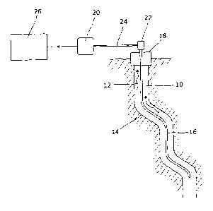
Figure 1 shows schematically an embodiment of the invention
implemented in an oil or gas well;
Figure 2 shows how movement of a feature in a vibrational signal detected
using the arrangement of figure 1 may be analysed to determine an indication
of
fluid flow; and
Figure 3 illustrates the intensity of a vibrational signal determined as a
function of time and distance along a gas well using an arrangement as
illustrated
in figure 1.
Detailed description of preferred embodiments
Referring now to figure 1 there is shown, schematically, apparatus for
monitoring fluid flow in a conduit 10 which carries a flowing fluid 12. In
this
example the conduit is provided by a well bore 14 which could be part of an
oil
CA 02800215 2012-11-21
WO 2011/148128 PCT/6B2011/000789
- 8 -
well or similar. A sensor optical fibre 16 which enters the wellhead through a
conventional fibre penetration system 18, and extends along the conduit. The
sensor optical fibre is optically coupled to an interrogator unit 20 by an
optical
coupling 22 and a link optical fibre 24. The interrogator 20 generates probe
light
using one or more lasers, and launches the probe light into the sensor optical
fibre 16. Some of the probe light is backscattered within the sensor optical
fibre
16, and backscattered probe light is detected and analysed by the interrogator
20. The time delay between launching a pulse of probe light into the fibre and
arrival back at the interrogator 20 of a particular portion of the
backscattered
probe light identifies the location along the fibre of the backscattering that
gave
rise to that portion of backscattered probe light. The nature of the
backscattering,
and hence properties of the backscattered light from any particular location
along
the sensor fibre, depend upon the properties of the sensor fibre at that
location,
which in turn is influenced by the environment around sensor optical fibre at
that
location.
The sensor fibre may be made up of a single length of a suitable optical
fibre, or if necessary may comprise multiple joined lengths of optical fibre.
Examples of optical fibre types which may be suitable for putting the
invention
into effect include single mode ITU-T G652 (SMF28), and multi-mode ITU-T
2o G651 (graded index 50/125).
Data relating to the properties of the backscattered light is passed from the
interrogator to an analyser 26 which derives information about the environment
around the sensor optical fibre from the properties of the backscattered
light. In
particular, the flow of the fluid 12 causes vibrations at the sensor fibre 16
which
influence backscattering of probe light within the sensor fibre, and the
analyser
derives a vibration signal both as a function of time and position along the
sensor
fibre. Sources of vibration in the flowing fluid 12 such as regions of
turbulent flow
move along the conduit 10 with the flowing fluid, and this gives rise to
features in
the derived vibration signal which change position with a velocity
characteristic of
the velocity of the flowing fluid. The analyser detects such moving features
and
automatically determines from their movement a measure of velocity of the
fluid
CA 02800215 2012-11-21
WO 2011/148128 PCT/GB20 1 1/000 789
9 -
flow. Alternatively, the vibration signal may be displayed graphically and a
measure of velocity of the fluid flow derived manually by a human operator.
The analyser may be implemented using computer apparatus, for example
a suitably programmed general purpose computer such as a laptop or other PC,
or a more specifically constructed data processing device, and may include
input
means such as a keyboard and pointer device, as well as visual display and
other
output means, for example to provide graphical indications of the vibration
signal,
the identified features, and determined measures of fluid flow as required.
Data
processing aspects of the interrogator 20 may be combined in with such
1o computer apparatus.
The vibration signal may be indicative of an intensity or power of vibration
across a wide frequency band, or features may be identified in more restricted
or
narrow frequency bands of vibration, or from combinations of sub features in
multiple frequency bands. Features may be or include peaks, troughs, periodic
signals of various other kinds, or any other features identifiable from the
vibration
signal which move or change in a way which is related to the fluid flow in a
manner sufficiently consistent for a measure of the fluid flow to be derived.
Vibration signals may be derived from the properties of the backscattered
probe light in a variety of ways. For example, a series of partially coherent
laser
pulses may be launched into an optical fibre, and the light which is received
continuously at the launched end, as a result of Rayleigh backscatter from
fibre
inhomogeneities, can be observed. Pulses are launched at intervals greater
than
the time needed for light to reach the far end of the fibre and to return to
the
launched end. This prevents backscattered light being received from more than
one pulse at a time. The backscattered signal detected at any instant
corresponds to the vectorial sum of all of the components of the light
reflected
from the illuminated section of fibre at the location of the optical pulse.
When the
fibre is unperturbed, the time-resolved backscatter signature is random but
stable. Any local external disturbance that changes the propagation constant
of
3 0 the fibre at a particular location perturbs the phase difference between
the
interfering waves at that location and can be detected as a modulation of the
attenuation trace by comparing the signal before and after the action of the
CA 02800215 2012-11-21
WO 2011/148128 PCT/CB2011/000789
- 10 -
disturbance. When the fibre cable is stretched, for example, by the action of
a
vibrational force, the strain state of the fibre changes at the location of
the
vibration, disturbing the spatial distribution of the Rayleigh scattering
centres.
This in turn causes a change in the back-reflected self-interference signal,
occurring only at the location of the perturbation, and this signal variation
can be
used to detect the existence and the character of the vibration. For more
details
on this technique, see WO 2006/048647 and WO 2008/056143.
Figure 2 is a graph showing example vibration signals derived by the
analyser 26, and shows how the analyser additionally determines a measure of
io fluid flow velocity from these signals. The abscissa of the graph
represents a
distance along the sensor optical fibre 16, which could, for example, equate
to a
range of depths of a few tens of metres within an oil well. The six curves
show
the detected vibration signal at successive time points, for example at
intervals of
one second, and the ordinate of the plotted data shows the strength of the
detected vibration signal at each point in time and space. A particular
feature in
the vibration signal is a vibration signal peak 30, which might typically be a
few
metres long, and which is seen to move to smaller distances over time. The
velocity of this movement is shown by gradient 32, which can be derived from
the
data by the analyser 26, for example by fitting a curve to the peak feature
and
using the apex of the fitted curve. The gradient 32 then provides a measure of
velocity of the flowing fluid. Of course other features of the vibration
signal such
as minima, periodic signals, or any other detectable moving feature could be
used to determine the measure of velocity.
The sensor optical fibre may be installed along the conduit in a variety of
ways, although different techniques have advantages and disadvantages in
respect of factors such as the intensity of coupling of fluid flow vibrations
to the
sensor fibre, likely erosion and damage to the sensor fibre, ease of
installation,
and so forth. Some suitable techniques for installing a sensor optical fibre
in an
oil or gas well include:
- running the sensor fibre in a stainless steel tube, for example of about
3mm diameter, the tube being filled with a silicon oil, and installing the
tube inside
or outside of the well production tubing;
CA 02800215 2012-11-21
WO 2011/148128 PCT/GB2011/000789
- 11 -
- running the sensor fibre in a 6mm stainless steel control line filled with
silicon oil or water, and installing the control line inside or outside the
production
tubing, or clamping the control line to another well insertion component;
- running the sensor fibre in a 14 mm carbon fibre rod pushed down
through the production tubing;
- incorporating the sensor fibre into the well casing or externally to the
well
casing.
Example vibrational data derived using a distributed optical fibre sensor
installed in a real tight gas production well is shown in figure 3. The well
is 6000
1o m in length and of horizontal formation, descending vertically for
approximately
3800 m after which the well path turns to run horizontally for the remaining
2200
m which forms the production zone. Within this production zone there are nine
production stages of significant operational interest. A pre-existing optical
fibre
structure was housed in the well structure, which contained a suitable, single
mode Corning SMF-28 (RTM) optical fibre. An interrogator was coupled to the
optical fibre and vibrational signals were acquired for the whole of the well
profile.
Vibrational events of interest, in which a feature in the vibrational signal
moves
along the fibre over time, were identified in production zones seven and nine,
which were the only two zones found to be producing.
Figure 3 is a plot where the grey scale density is indicative of vibrational
intensity. The abscissa represents well depth from 4583 m to 5962 m and the
ordinate represents increasing elapsed time. A number of ramp features can be
seen adjacent to production zone nine which is characterised by a dark
vertical
band on the plot labelled 52, with distance from the production zone
increasing
with time both in an upwards (leftward movement on the graph) and downwards
direction. A particular event of interest labelled as 54 on the plot comprises
a
peak in vibrational intensity which moves upwards in the well at a velocity of
approximately 78.3 metres per second, indicating a corresponding velocity of
fluid
flow in that region of the well.
A range of modifications and variations may be made to the described
embodiments without departing from the scope of the invention. For example the
analyser 26 and interrogator 20 of figure 1 may be implemented in a single
unit.
CA 02800215 2012-11-21
WO 2011/148128 PCT/CB2011/000789
- 12 -
The interrogator 20 may be implemented using an optical based sub-component
coupled to a separate computer based signal processing sub-component, and
these subcomponents may be provided in separate units suitably connected.
Probe light pulses may be generated using a pulsed laser source or by
modulation of continuous wave light.