Note : Les descriptions sont présentées dans la langue officielle dans laquelle elles ont été soumises.
CA 02802255 2013-01-17
11-PCS-107(230)
- 1 -
ENCLOSED SWITCH INCLUDING A SHUNT TRIP MECHANISM
BACKGROUND
Field
The disclosed concept pertains generally to enclosed switches and, more
particularly, to enclosed switches, such as, for example, dead-front switches,
safety
switches and disconnects.
Background Information
Enclosed and dead-front switches are defined by UL Standard 98. These
include individually enclosed air switches, rated 4000 A or less at 600 V or
less, having all
current-carrying parts enclosed, and manually operable by means of external
handles.
There is room for improvement in electrical switching apparatus, such as
enclosed switches.
SUMMARY
These needs and others are met by embodiments of the disclosed concept,
which provides an enclosed switch including a shunt trip mechanism. As a
result, a
manually operated enclosed switch can be tripped open by an external signal.
In accordance with embodiments of the disclosed concept, an enclosed
switch comprises: a switch assembly comprising separable contacts; an
operating
mechanism structured to open and close the separable contacts; and a shunt
trip
mechanism cooperating with the operating mechanism to trip open the separable
contacts,
wherein the operating mechanism comprises a manual operating mechanism.
The shunt trip mechanism may be structured to operate and engage the
operating mechanism only when the manual operating mechanism is in a closed
position.
The manual operating mechanism may comprise a manual operating
handle; the shunt trip mechanism may further comprise a pawl lever; a latch
lever, when
released, may cause rotation of the pawl lever to disengage the manual
operating handle
from the manual operating mechanism; and the manual operating handle moves to
an
intermediate position between a closed position and an open position thereof
in response
to release of the latch lever.
The manual operating mechanism may comprise a pair of wheels normally
coupled together by a coupling member mounted to one of the wheels and an
opening in
the other one of the wheels; the manual operating handle may be rotatably
coupled to the
CA 02802255 2013-01-17
11-PCS-107(230)
- 2 -
one of the wheels; and rotation of the pawl lever may cause the other one of
the wheels to
decouple from the one of the wheels, thereby allowing the manual operating
handle to
move to the intermediate position.
The shunt trip mechanism may comprise a trip shaft; the operating
mechanism may comprise a first pair of wheels normally coupled together by a
plurality of
coupling members of the wheels; a first one of the first pair of wheels may
comprise a
latch arm normally held by the trip shaft; rotation of the trip shaft may
release the latch
arm of the first one of the first pair of wheels; the first one of the first
pair of wheels may
be biased to cause rotation of a second one of the first pair of wheels to an
off position
thereof, in order to open the separable contacts; the manual operating
mechanism may
comprise a second pair of wheels normally coupled together by a pawl lever
coupled to
one of the second pair of wheels and an opening in the other one of the second
pair of
wheels; the manual operating handle may be rotatably coupled to the one of the
second
pair of wheels; the shunt trip mechanism may further comprise a pawl lever to
disengage
the manual operating handle from the manual operating mechanism; the manual
operating
handle may move to an intermediate position between a closed position and an
open
position thereof in response to the pawl lever causing the other one of the
second pair of
wheels to decouple from the one of the second pair of wheels, thereby allowing
the
manual operating handle to move to the intermediate position.
BRIEF DESCRIPTION OF THE DRAWINGS
A full understanding of the disclosed concept can be gained from the
following description of the preferred embodiments when read in conjunction
with the
accompanying drawings in which:
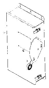
Figure 1 is an isometric view of an enclosed or dead-front switch in
accordance with embodiments of the disclosed concept.
Figure 2 is a side vertical elevation view of the switch of Figure 1.
Figure 3 is a vertical elevation view of the switch of Figure 1 with the front
cover removed to show internal structures.
Figure 4 is an exploded isometric view of the shunt trip mechanism of the
switch of Figure 1.
Figure 5 is an isometric view of the shunt trip mechanism of Figure 4 in the
off position by shunt trip, ready to restore the opening spring to a charged
position.
CA 02802255 2013-01-17
11-PCS-107(230)
- 3 -
Figure 6 is an isometric view of the shunt trip mechanism of Figure 4 in the
opening spring charged position and the switch in the on position.
Figure 7 is an isometric view of the shunt trip mechanism of Figure 4 in the
discharged position with the switch open.
Figure 8 is an isometric view of the shunt trip mechanism of Figure 4 in the
off and discharged position with some parts removed to show engagement of the
first and
second wheels.
Figure 9 is an isometric view of the shunt trip mechanism of Figure 4 in the
charged position showing the pawl lever in the engaged position, switch
closed.
Figure 10 is an isometric view of the shunt trip mechanism of Figure 4 in
the tripped position showing the pawl lever disengaged position, switch opened
by shunt
trip.
DESCRIPTION OF THE PREFERRED EMBODIMENTS
As employed herein, the term "number" shall mean one or an integer
greater than one (i.e., a plurality).
As employed herein, the term "enclosed switch" shall mean a switch
defined by UL Standard 98. Such an enclosed switch is also commonly referred
to as a
dead-front switch, a safety switch or a disconnect (switch).
As employed herein, the statement that two or more parts are "connected"
or "coupled" together shall mean that the parts are joined together either
directly or joined
through one or more intermediate parts. Further, as employed herein, the
statement that
two or more parts are "attached" shall mean that the parts are joined together
directly.
Referring to Figures 1-6, the disclosed shunt trip mechanism 100 (Figure 4)
enables an enclosed switch 102 (Figure 3) of an operating mechanism, such as a
side
mounted mechanism 104, to be relatively quickly opened with a momentary
electrical
signal (not shown). The side mounted mechanism 104 is manually reset upon a
subsequent manual operation to an "off' (or open) position (Figure 5) and then
to an "on"
(or closed) position (Figure 6) to close separable contacts 106 (Figure 6) of
the enclosed
switch 102.
The side mounted mechanism 104 employs stored mechanical energy to
trip open the switch separable contacts 106, when using a manual operating
mechanism 3
of a main switch assembly 38 (Figure 3). During normal, non-automatic opening
of the
enclosed switch 102, normal manual operation with an operating handle 36
bypasses the
CA 02802255 2013-01-17
11-PCS-107(230)
- 4 -
shunt trip mechanism 100. The shunt trip mechanism 100 is structured to
operate and
engage only when the manual operating mechanism 3 is in the "on" (or closed)
position
(Figure 6). When the manual operating mechanism 3 is in the closed position, a
solenoid
108 of the shunt trip mechanism 100 is enabled with contacts (not shown) of
micro-switch
24A being closed when its arm 25 is not engaged by cam surface 110 (Figure 4)
of wheel
three 15 as shown in Figures 4 and 6. Conversely, the solenoid 108 is disabled
with
contacts (not shown) of micro-switch 24A being open when its arm 25 is engaged
by cam
surface 110 of wheel three 15 as shown in Figure 7.
When current flows in the solenoid 108 with micro-switch 24A closed, the
solenoid plunger 112 is pulled in. This rotates clockwise (with respect to
Figures 4, 6 and
7) trigger lever latch 114 that, in turn, releases a trip latch lever 10 (as
shown in Figure 7).
The trip latch lever 10 performs two actions in tandem with energy stored in a
latch shaft
drive spring 30 that biases the lever 10 at one end and is fixed at its other
end at an
opening (not shown) in trip shaft bracket 9 (Figure 4). These two actions
include: (1)
rotation of the pawl lever 75; and (2) rotation (counter-clockwise with
respect to Figures 4,
6 and 7) of the trip shaft 26.
Rotation of the bushing shaft 73 of actuator bushing 74 of the pawl lever 75
is made with edge 10A of the trip latch lever 10. At this actuation of the
pawl lever 75,
the pawl bushing 81 of pawl bushing shaft 80 exits opening, such as slot 144,
in wheel
three 15, causing coupling to be lost between wheel three 15 and wheel four 6.
This
releases operating handle coupling 5 and allows the manual operating handle 36
to move
to an intermediate position (Figure 7) indicating that the switch 102 is in a
tripped state.
The movement of the manual operating handle 36 to the intermediate position is
facilitated
by extension spring 77 and extension spring anchor 78 of wheel four 6. The
pawl lever 75
is pivotally coupled to the wheel four 6 at opening 83 by pawl lever bearing
shaft 79.
Return bias (clockwise with respect to Figure 4) for the pawl lever 75 is
provided by pawl
lever return spring 76, which is coupled to another opening 84 of wheel four
6.
During actuation of the pawl lever 75 (Figure 10), this disengages pawl
lever 75 bushing 81 and shaft 80 coupling wheel three 15 and wheel four 6,
thereby
releasing the handle coupling 5 to allow the operating handle 36 to move to an
intermediate position (Figure 7) in response to the trip latch lever 10 and
the
corresponding spring 30, in order to indicate that the enclosed switch 102 is
in a tripped
state. Rotation of the trip shaft 26 causes the latch arm 130 of wheel one 20
to pass
CA 02802255 2013-01-17
11-PCS-107(230)
- 5 -
through center 146 of the trip shaft 26 and the latch arm 130 is released by
the flat 128 of
the trip shaft 26.
Wheel four 6 is coupled to operating handle coupling 5 upon which the
operating handle 36 (Figures 1-3) is coupled. Wheel four 6 has a bearing
socket 124 for a
round end 126 (Figure 8) of a hexagonal shaft 8 (Figure 4). The hexagonal
shaft 8
engages corresponding openings of the manual mechanism coupling 22, wheel two
19 and
wheel three 15 for rotation therewith. The manual mechanism coupling 22 is
fastened to
the manual operating mechanism 3 for rotation therewith. Rotation of the trip
shaft 26 and
the flat 128 thereof then releases latch arm 130 of wheel one 20.
Wheel one 20, when unlatched by the trip shaft 26, causes counter-
clockwise (with respect to Figures 4-7) rotation of wheel two 19 to the off
position
thereof. Wheel two 19, when reset, causes clockwise (with respect to Figures 4-
7) rotation
of wheel one 20 to the latched position thereof. Otherwise, wheel one 20 is in
a fixed
position when latch arm 130 thereof is latched by the trip shaft 26. Rotation
of wheel one
20 is provided by the stored energy in opening spring 31, which is fastened by
a fastener
156 (Figures 4, 9 and 10) at one end and engages a groove (not shown) of wheel
one 20 at
the other end. Arms 132 of wheel two 19 engage raised projections 134 of wheel
one 20
(as best shown in Figure 8), allowing the turning force to be conveyed to the
hexagonal
shaft 8 (Figure 4), which rotates the manual mechanism coupling 22. As wheel
one 20
(when unlatched), wheel two 19, the hexagonal shaft 8, and the manual
mechanism
coupling 22 rotate counter-clockwise (with respect to Figures 4-7) together,
the manual
operating mechanism 3 is rotated into the off position, thereby opening the
main switch
assembly 38. The rotation of wheel one 20 is stopped by a bumper arm 136 of
wheel one
20 and bumper 71. The operating handle 36 then remains at an intermediate
position
(Figure 7) between the on and off position, indicating that the enclosed
switch 102 has
been electrically tripped.
The trip shaft 26 is rotatably supported by mechanism bracket 13 (Figure 4)
at one end, a cylindrical spring support 32 within trip shaft bracket 9, and a
retaining ring
16 and washer 33 forming the joint 148 (Figure 7) at the other end.
When the main switch assembly 38 is to be closed after an electrical trip,
the operator moves the switch operating handle 36 to the "off' (or open)
position (Figure
5) and then to the "on" (or closed) position (Figure 6). This causes two
resetting actions in
the shunt trip mechanism 100 by the pin and sleeve bushing 138 at the end 140
of arm 142
CA 02802255 2013-01-17
11-PCS-107(230)
- 6 -
of wheel four 6 moving the trip latch lever 10 with surface 10B toward the
trigger lever
latch 114. With this lever rotation, energy is again stored in the latch shaft
drive spring 30
for the next electrical trip operation. The extension spring 76 causes
rotation of the pawl
lever 75 in turn causing the pawl bushing 81 of pawl bushing shaft 80 to re-
engage and re-
enter slot 144 in wheel three 15, during the reset rotation of wheel four 6,
causing coupling
to be restored between wheel three 15 and wheel four 6. The pawl bushing 81 is
retained
to the pawl bushing shaft 80 by pawl bushing retainer 82. The handle
indication extension
spring 77 being anchored to wheel four 6 and the pawl lever return spring 76
being
anchored to pawl lever 75 causes pawl lever 75 carrying the pawl bushing 81 of
pawl
bushing shaft 80 to return to the slot 144 of wheel three 15 as it
independently pivots with
respect to wheel four 6 during the resetting action. When wheel three 15 and
wheel four 6
are aligned by stop 158 (shown in Figures 4, 5 and 7) while the manual
operating handle
36 is at the off position, the pawl extension spring 76 can then draw the pawl
bushing 81
into the wheel three 15 slot 144 to restore the coupling.
First, in response to the "off' position, a pin 138 (Figure 7) (best shown in
Figure 5) at end 140 of arm 142 of wheel four 6 moves (clockwise with respect
to Figures
4-7) the trip latch lever 10 toward the trigger lever latch 114. With this
rotation of the if
latch lever 10, sufficient energy (e.g., without limitation, spring 30 is
wound about 180
from its relaxed state) is again stored in the latch shaft drive spring 30 for
the next
electrical trip operation, and rotation of the pawl lever 75 (Figure 4),
thereby re-engaging
wheel four 6 to wheel three 15 with the slot 144 in wheel four 6 being engaged
by pawl
lever bushing 81. Also, during this first closure operation of the main switch
assembly 38
after an electrical trip, the opening spring 31 is recharged simultaneously
through the
engagement of wheel two 19 and wheel one 20 with the arms 132 and the raised
projections 134. This is shown in Figure 8.
Second, in response to the "on" position, at the closing position of the main
switch assembly 38, the latch arm 130 of wheel one 20 touches and rotates the
trip shaft
26 (counter-clockwise with respect to Figures 4-7) at the section where the
flat 128 is at
the depth of the center 146 of the trip shaft 26. Rotation of the trip shaft
26 is allowed by
joint 148 (Figure 5) at shaped opening 152 (Figure 8) of the trip latch lever
10 and a flat
end 150 (Figure 4) of the trip shaft 26, which allows counter-clockwise
rotation (with
respect to Figures 5 and 6) of the trip shaft 26 for the latching function.
The flat end 150
of the trip shaft 26 and the shaped opening 152 for the shaft 26 in the trip
latch lever 10
CA 02802255 2013-01-17
11-PCS-107(230)
- 7 -
allow for the shaft 26 to rotate counter-clockwise during reset of wheel one
20 and then
back clockwise with the torque from the trip shaft 26 spring 29 (with respect
to Figures 5
and 6) to latch and hold wheel one 20 in the latched position.
After a reset and closure operation, for a trip operation, the latch lever 10
can then pivot counter-clockwise (with respect to Figures 4-7). As shown in
Figure 8, the
trip latch lever 10 is latched and wheel one latch arm 130 is unlatched. After
latching of
the latch arm 130, tripping operation proceeds as follows. The trigger latch
lever 114
releases the trip latch lever 10 to rotate counter-clockwise. The shaped
opening 152 in the
trip latch lever 10 engages the flat end 150 of the trip shaft 26 and causes
the trip shaft 26
to also pivot counter-clockwise (with respect to Figures 4-8). This counter-
clockwise
shaft rotation allows the latch arm 130 of wheel one 20 to pass through center
146 of the
trip shaft 26 and the latch arm 130 is released by the flat 128 of the trip
shaft 26.
Following a trip operation and until the reset operation is fully completed,
wheel three 15 is disengaged from the handle 36 by rotation of the pawl lever
75,
removing the pawl bushing 81 from slot 144. Otherwise, the handle 36 is
engaged with
wheel three 15 and, thus, with the hexagonal shaft 8, wheel two 19, the manual
mechanism
coupling 22 and the manual operating mechanism 3 for rotation therewith.
During manual operation, the arms 132 of wheel two 19 do not rotate wheel
one 20 by virtue of the angular spacing of the raised projections 134. The
wheel spring 21
sustains axial contact of wheel two 19 to wheel one 20.
As shown in Figure 5, counter-clockwise rotation of wheel three 15 is
stopped by stop 158 and support bracket 14.
The enclosed switch 102 also includes a door latch 160 and a door interlock
162.
The auxiliary switch 24 of Figure 4 is used for external signal circuits (not
shown).
While specific embodiments of the disclosed concept have been described
in detail, it will be appreciated by those skilled in the art that various
modifications and
alternatives to those details could be developed in light of the overall
teachings of the
disclosure. Accordingly, the particular arrangements disclosed are meant to be
illustrative
only and not limiting as to the scope of the disclosed concept which is to be
given the full
breadth of the claims appended and any and all equivalents thereof.