Note : Les descriptions sont présentées dans la langue officielle dans laquelle elles ont été soumises.
CA 02802270 2012-12-11
CSL BEHRING GMBH 2010 M002_A159
BIN/am
06.15.2011
Holder for an injection syringe
The present invention relates to a holder for a syringe
for self-medication purposes, in particular for placing
on a supporting surface.
Particularly in the context of intravenous or
subcutaneous administration of medicaments, the active
substance, which in most cases is liquid, is delivered
to the body tissue using a syringe or comparable
injection devices. Particularly in self-medication or
home-based therapy, medicines of this kind require
suitable training of the patient. For example, if a
product for treating hemophilia is to be administered,
this is in most cases done using what is called a
butterfly cannula.
A patient applies this to the inner aspect of his
elbow, for example. However, the patient then has only
one hand available for the actual injection procedure.
A further consideration is that the product to be
administered has a higher viscosity than water, such
that the patient has to apply considerable force to a
syringe plunger in order to inject the active
substance. This maneuvering of the injection syringe
with one hand is quite awkward and difficult. In
particular, there is the danger that a fluid-conveying
hose, which connects the syringe outlet to an injection
needle, will become kinked during the injection
procedure, which makes delivery of the product even
more difficult.
It should also be remembered that hemophiliac patients
in particular already suffer from secondary diseases
and often have limited mobility and dexterity. Stiff
CA 02802270 2012-12-11
- 2 -
joints, especially in the area of the forearms and
hands, can make self-medication very difficult.
Therefore, the object of the present invention is to
make available a holder for an injection syringe,
specifically a holder which permits simple, safe and
reliable injection and facilitates the handling of an
injection syringe, or of an injection set comprising an
injection hose, a needle and a syringe.
The object of the invention is achieved with the aid of
a holder according to independent claim 1. Individual
advantageous embodiments of the invention form the
subject matter of the dependent claims.
The holder according to the invention is designed in
particular for an injection syringe. It has a housing
designed to receive the syringe, and a stand for
placing the holder on a supporting surface. Moreover,
the holder is provided with retaining means for axially
and/or radially fixing the syringe on or in the holder.
The retaining means are designed in such a way that an
outlet of the syringe in the holder is arranged facing
the free end of the stand and at a distance therefrom,
that is to say comes to lie at a suitable distance from
the supporting surface on which the holder is to be
placed. In particular, provision is made for the
retaining means of the holder to be designed to fix a
syringe inside or on the holder such that, when a
holder is placed on a supporting surface, the syringe
outlet is oriented toward the supporting surface but at
a distance therefrom, and the syringe in the holder is
arranged vertically, i.e. substantially parallel to the
axial direction of the stand and of the holder.
The possibility of placing the holder almost
perpendicularly on a supporting surface already
simplifies the handling of the syringe for injection
CA 02802270 2012-12-11
- 3 -
purposes. For example, the user can grip the holder
with four fingers, while using the thumb to apply a
downwardly directed injection force to the retracted
syringe plunger. It proves advantageous here that the
syringe holder can be safely placed on a supporting
surface and that the forces to be applied to the
syringe plunger for injection purposes can be diverted
via the syringe body into the holder and, finally, onto
or into the supporting surface. In cases where the user
is unable to apply the necessary injection force with
his thumb alone, the holder also makes it possible to
use other parts of the body, for example the flat of
the hand, to apply pressure to the syringe plunger,
without increased danger of kinking the hose that
fluidically connects the cannula and the syringe to
each other.
The stand is advantageously designed for placing on a
substantially flat supporting surface, for example a
table. For this purpose, for example, the stand can
have a set-down edge which extends at least in part
about the periphery and which lies substantially in the
plane perpendicular to the longitudinal direction of
the syringe.
According to a first preferred embodiment of the
invention, provision is therefore made that the
retaining means provided on the holder for the syringe
allow the syringe to be axially fixed in or on the
holder in such a way that the distance of the syringe
outlet from the end of the stand corresponds at least
to the axial extent of a hose attachment piece plus a
minimum hose bend radius at which the hose in fluid
connection with the syringe outlet remains open to
fluid. This has the effect that the hose to be arranged
on the syringe outlet is as it were freely suspended in
the holder receiving the syringe. In this way, kinking
of the fluid-carrying hose is effectively prevented.
CA 02802270 2012-12-11
- 4 -
The holder is advantageously suitable for receiving
syringes of different sizes. In particular, the holder
should be designed for 5-milliliter, 10-milliliter or
20-milliliter disposable syringes. Depending on the
preferred syringe type, the distance between the
syringe outlet and the end of the stand is intended to
be adapted, or is adapted, to the corresponding hose
attachment piece and the corresponding hose diameter or
minimum hose bend radius. Given his specialist
knowledge and his familiarity with the characteristic
features of corresponding syringes and hoses, e.g. the
length of the syringes and of the attachment pieces and
the diameter and flexibility of the hose, a person
skilled in the art is able to do this without himself
having to be inventive.
According to a development of the invention, provision
is also made that the housing of the holder, at its
upper end portion directed away from the stand, has a
radially outwardly protruding contact flange, which is
arranged at least in part about the periphery. This
contact flange can effectively prevent the housing from
slipping through the user's hand that surrounds the
housing. In scenarios where an injection force is to be
applied to the syringe plunger by means of the thumb,
the other four fingers of the hand surround the housing
of the holder. The radially outwardly protruding
contact flange, arranged at least in part about the
periphery, preferably comes to lie on the side of an
index finger directed toward the thumb.
According to a development of the invention, provision
is also made that the housing widens radially toward
the stand. It is particularly preferable that the
housing has an at least partially cylindrical main
structure provided with a grip surface on the outside.
The grip surface itself can be adapted, for example, to
CA 02802270 2012-12-11
-
the ergonomics of a human hand. For example, it can
have an appropriate surface structure, for example a
ribbed arrangement adapted to the individual fingers of
a human hand. Alternatively, it can of course also have
5 a substantially smooth contour, for example a circular
or oval contour.
The radial widening of the housing improves the
stability of the housing on the supporting surface. For
example, provision can be made that the housing
radially widens toward the stand either conically or
otherwise. In this way, even when very high injection
forces are applied, it is possible to largely avoid, or
indeed eliminate, accidental toppling of the holder or
kinking of the syringe hose during an injection
procedure.
In a particular embodiment, the housing, the stand
and/or the contact flange lying opposite the stand are
formed in one piece. In this case, provision is
preferably made to produce the housing, the stand
and/or the contact flange in the form of a single
injection-molded component, preferably an injection-
molded plastic component. The design as an injection-
molded plastic component is relatively simple and
inexpensive.
Moreover, according to a preferred embodiment of the
invention, provision is made that the housing has a
radially accessible seat for insertion of the syringe
into the housing. Considering the cylinder symmetry of
the syringe, or of the syringe body that receives the
medicament, provision is thus made for the syringe to
be inserted into the seat of the housing transversely
with respect to the longitudinal direction of the
syringe, that is to say transversely with respect to
the axial direction. Accordingly, the housing does not
have strict cylinder symmetry and is instead formed
= CA 02802270 2012-12-11
- 6 -
only part way round the circumferential direction,
being designed for example as a cut-open hollow
cylinder toward the insertion opening provided for the
syringe, which cut-open hollow cylinder can be closed
by means of a separate closure mechanism after
insertion of a syringe and thus fixes the latter.
Alternatively or in addition to this, however, it is
also conceivable to insert the syringe into the holder
from above in the axial direction, that is to say in
the longitudinal direction of the syringe, until the
syringe comes to lie, with its outwardly protruding
retaining projections formed at the upper end of the
syringe body, on abutment surfaces or bearing surfaces
provided for this purpose on the holder. The syringe
would then in some cases be fixed on the holder only
unidirectionally in the axial direction, namely in the
injection direction, with the holder itself functioning
as a hollow cylindrical seat for the syringe body.
For the invention, provision is preferably made that
the holder can receive syringes of different sizes. The
holder should in particular be designed for 5-
milliliter, 10-milliliter or 20-milliliter disposable
syringes and should be able to fix all syringe formats,
or at least the three syringe formats mentioned, both
in the radial direction and in the axial direction for
injection purposes. In this connection, it proves
advantageous if at least one retaining wing is mounted
pivotably in the syringe seat of the holder, which at
least one retaining wing can be brought into clamping
contact with the syringe body when the syringe is
inserted into the seat, i.e. with which at least one
retaining wing the syringe can be clamped into the
holder. The at least one retaining wing makes available
a kind of radial locking mechanism for the syringe and
ensures that all of the aforementioned syringe sizes,
CA 02802270 2012-12-11
- 7 -
each with different diameters, can be fixed in the
syringe seat of the holder.
Provision is advantageously made that the at least one
retaining wing is mounted on a pivot axle extending
substantially parallel to the axial direction of the
holder or parallel to the longitudinal extent of the
syringe, under the effect of at least one spring
element, preferably a torsion spring. Thus, provision
can be made to pivot the retaining wing counter to the
spring force during insertion of the syringe, with the
result that, when an end position of the syringe in the
holder is reached, the retaining wing, with the aid of
the retaining force applied by the spring, keeps the
syringe in the predetermined position, at least in the
axial direction.
According to a preferred embodiment, two retaining
wings are provided, which extend parallel to each
other, are articulated pivotably on the holder and,
depending on the pivoting position, form a syringe seat
of variable size. The provision of two retaining wings
means that syringe bodies of different sizes can easily
be fixed in the holder. It also proves advantageous if
the retaining wings have at least in some areas, in the
plane perpendicular to the axial direction, that is to
say perpendicular to the plane of their pivot axle, a
curvature adapted to the syringe body. Seen from the
direction of the seat, the curvature of the retaining
wings is preferably convex from the inside, such that
the syringe body, which is of typically round design in
the circumferential direction, comes to bear on the
retaining wings across the greatest possible surface
area. Depending on the preferred syringe type, the
curvature of the retaining wings is to be adapted to
the curvature of the syringe body, or it is adapted
thereto.
CA 02802270 2012-12-11
- 8 -
According to another preferred embodiment of the
invention, provision is further made that the at least
one retaining wing, at an end portion opposite its
pivot axle, i.e. at its free end portion, has a
substantially radially outwardly protruding end
portion, which functions as an insertion aid for the
syringe. Seen in the direction in which the syringe is
fitted, the retaining wing tapers inward before forming
a concavely curved seat for the syringe body.
During the insertion of the syringe, the end portion
widening radially toward the free end of the retaining
wings not only serves as an insertion aid but can also
ensure, during insertion of the syringe body into the
seat, that the retaining wings pivot outward and thus
only then free the seat for the syringe body. After the
syringe body with its full radius has passed this
narrowing, the retaining wings can pivot back in the
direction of their original configuration, under the
effect of the retaining force provided by the torsion
spring, and can clamp the syringe body between
themselves.
According to another advantageous embodiment of the
invention, provision is further made for at least one
retaining means to be designed in the form of a closure
piece mounted pivotably or rotatably on the housing,
such that the seat provided for the syringe can be
closed by means of the closure piece. A configuration
of this kind is provided particularly if the housing of
the holder is only cylindrical in part and open to one
side, and it is designed for radial insertion of the
syringe and ensures that, in this embodiment too, the
syringe is fixed in the holder.
In a preferred embodiment, the closure piece is
designed as a flap-like closure which is pivotably
articulated on one side of the syringe seat and, after
CA 02802270 2012-12-11
- 9 -
insertion of the syringe into the seat, can be pivoted
to the opposite cheek of the housing and fixed there.
The fixing is preferably provided here by a locking
mechanism composed of housing cheek and pivotable
closure piece. The closure piece itself is preferably
designed as a locking means that at least in part
encloses the syringe seat in the circumferential
direction of the housing and in the longitudinal
direction of the syringe. In other words, the closure
piece is designed as a locking means which at least in
part encloses the seat in the circumferential direction
of the housing and in the longitudinal direction of the
syringe and which engages with a mating locking means
arranged on the outside of the housing. In order to
close the syringe seat, it cooperates with a mating
locking means arranged on the outside of the housing or
on the corresponding housing cheek. Although the
syringe can already be fixed on the holder, as seen in
the radial direction, with the aid of the at least one
retaining wing, the closure piece arranged pivotably on
the housing forms a further safety measure against
inadvertent release of the syringe from the housing or
from the holder.
According to another advantageous embodiment of the
invention, provision is further made that the closure
piece mounted pivotably on the housing has, on its
inner face directed toward the syringe, at least one
toothed surface or toothing designed to engage with a
correspondingly formed beveled surface or chamfer at
the end of the at least one retaining wing, in such a
way that the retaining wing pivots radially inward
toward the syringe under the action of a radially
inwardly directed force applied to the closure piece.
In other words, the closure piece engages on the inside
with the radially outwardly directed free end portion
of at least one retaining wing or preferably two
CA 02802270 2012-12-11
- 10 -
retaining wings, wherein an inwardly directed pressure
applied to the closure piece causes the retaining wing
to pivot radially inward and can thus bring about a
clamping action between retaining wing and syringe.
It proves particularly advantageous here if the closure
piece has two surface segments which are arranged next
to each other in the circumferential direction and
connected flexibly to each other and on each of which
an inner toothed surface engages with a beveled surface
at the end of a retaining wing. The two surface
segments of the closure piece are arranged lying next
to each other, as seen in the circumferential
direction, and are able to pivot relative to each other
along an axis extending in the axial direction. By
virtue of this pivotability or bendability of the
closure piece, each of the inward and at least
partially toothed surface segments can exert a radially
inwardly directed force on the retaining wings arranged
pivotably in the seat. In this way, it is also possible
for one and the same holder to be used to fix syringes
of different sizes.
In an alternatively preferred embodiment, the closure
piece is designed to be rotatable about the axial
direction in relation to the housing, wherein the
closure piece is designed with an area which, after
partial rotation about the longitudinal direction of
the syringe, fixes the syringe in the seat of the
housing. In other words, the closure piece, after
partial rotation, serves to fix the syringe in the seat
of the housing and prevent the syringe from sliding or
from slipping out.
The rotatable closure piece is advantageously designed
to rotate perpendicularly with respect to the axial
direction of the holder and about the longitudinal axis
CA 02802270 2012-12-11
- 11 -
of the syringe. Particularly preferably, the rotatable
closure piece is designed in one piece as a screw cap.
For example, the rotatable closure can be designed as a
kind of open ring which radially encloses the syringe
seat at least in part and has an opening and which,
after insertion of the syringe into the seat, is
rotatable about the longitudinal direction of the
syringe, as a result of which the opening in the ring
is laterally rotated and, in this way, the syringe is
fixed in the seat. The rotatable closure piece proves
especially easy to handle, particularly with one hand,
and is therefore particularly advantageous.
In another preferred embodiment of the holder,
provision is further made that the closure piece only
partially covers the area of the syringe seat as seen
in the axial direction. In particular, the lower
portion of the syringe directed toward the stand should
not be covered by the closure piece, and instead it
should remain visible so that the user can visually
check the filling level of the syringe during the
injection procedure.
Moreover, for the invention, provision is preferably
made that the at least one retaining wing and/or the
housing itself at its upper end portion directed away
from the stand and/or the closure piece located at the
upper end portion of the housing directed away from the
stand has/have at least one slit or a bearing for a
radially outwardly protruding retaining projection or
two diametrically radially outwardly protruding
retaining projections of a syringe, in order to fix the
syringe axially on the holder, at least as seen in the
injection direction.
For the slit provided in the upper portion of the
retaining wings, an insertion bevel can further be
CA 02802270 2012-12-11
- 12 -
provided for the retaining projections of the syringe,
such that, during insertion of the syringe into the
seat, a clamping action can also already be obtained in
the area of the retaining projections and the slits on
the retaining-wing side. If receiving slits for the
syringe-side retaining projections are already provided
in the retaining wings, the syringe can be fixed
bidirectionally on the holder in the axial direction.
In embodiments of the holder without retaining wings or
without slits in the retaining wings, it may however
also be sufficient if the at least in part
circumferentially formed housing of the holder forms a
bearing for the syringe-side retaining projections, at
least slightly below the radially outwardly protruding
contact flange. Thus, when the holder is placed on a
supporting surface, the syringe is fixed solely by its
weight and, when an injection force is applied that
acts on the syringe plunger, it is axially fixed with
its retaining projections on the housing-side bearing,
for example by being supported thereon.
Further aims, features and advantageous configurations
of the invention are explained in the following
description of illustrative embodiments, with reference
to the figures. All of the features described in the
text and also depicted in the figures form, both
individually and in any meaningful combination with one
another, the subject matter of the present invention.
In the drawing:
Fig. 1 shows a perspective view of a syringe holder in
a first embodiment, with the closure closed,
Fig. 2 shows the syringe holder according to Fig. 1
with the closure opened,
CA 02802270 2012-12-11
- 13 -
Fig. 3 shows the holder according to Fig. 2 without an
inserted syringe,
Fig. 4 shows a perspective view of a further
embodiment of a holder, with retaining wings
slit in the radial direction,
Fig. 5 shows the holder according to Fig. 4 with an
inserted syringe,
Fig. 6 shows an enlarged detail of the syringe holder
according to Figure 5,
Fig. 7 shows a perspective view of a cross section
through the holder according to Figures 4 to 6
at the height of the toothing provided on the
closure,
Fig. 8 shows a partially cutaway rear view of the
holder according to Figures 4 to 7,
Fig. 9 shows a perspective view of a syringe holder in
a further embodiment with a rotatable and
opened closure, and
Fig. 10 shows an enlarged detail of the rotatable
closure according to Fig. 9.
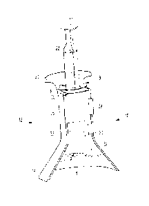
A holder 10 for receiving an injection syringe 18 is
shown in Figures 1 to 3. The holder 10 has a seat 16,
for example for a disposable syringe 18 which, by way
of example, has a substantially cylindrically
symmetrical syringe body 20 and a syringe plunger 22
axially movable therein. At the end directed away from
the syringe outlet 26 of the syringe body 20, the
syringe plunger 22 has a pressing or forcing surface 24
via which, for example, the user can use his thumb to
CA 02802270 2012-12-11
- 14 -
subject the syringe plunger 22 to the force needed to
inject a liquid.
The holder itself is designed as an injection-molded
component, preferably from thermoplastic. The holder 10
has a syringe housing 12 which, toward the bottom, has
a radially widening, for example conically extending
stand 14, and, at the top toward the syringe plunger
22, has a radially outwardly protruding contact flange
30. Between these, the housing 12 has a grip surface
32. The latter can be ergonomically adapted, for
example, to the inner contour of a hand. For injection
purposes, it is advantageous if the user applies
pressure to the pressing piece 24 from above using his
thumb, and if the side of the index finger directed
toward the thumb is placed for support on the underside
of the radially protruding contact flange 30.
By means of the conically or radially widening stand,
the entire holder 10 can be placed safely on a
supporting surface (not shown explicitly in the
figures). This facilitates the injection procedure and
allows the user to apply in a controlled manner the
force needed for a slow and smooth injection. It is
essential here that the syringe outlet 26 comes to lie
at an axial distance from the supporting surface on
which the holder 10 is to be placed. In this way, a
hose piece, connected fluidically to an injection
device passing into the body tissue, can be coupled as
it were in a freely suspended manner to the outlet 26
of the syringe 18. Standardized connector components
are preferably used, for example Luer lock couplings.
In the axial direction, which runs substantially in the
vertical direction in all of Figures 1 to 8, the
syringe 18 that comes to lie in the seat 16 is
supported by its retaining projections 28, which
protrude radially from the syringe body 20, on an upper
CA 02802270 2012-12-11
- 15 -
end portion 80 of the housing 12. This end portion 80
functioning as a bearing is arranged slightly below the
contact flange 30. This is advantageous to the extent
that users with a relatively short thumb are also able
to easily actuate a plunger 22 of a relatively large
syringe, for example of a 20-ml syringe, for injection
purposes.
As can be seen in Fig. 3, the injection-molded housing
12 has, in the area of the conical widening of the
stand 14, a web plate 34 which, on the one hand,
increases the torsional rigidity and stability of the
housing 12 and, on the other hand, can function as a
seat for the pivot axles 56, 58 of the two retaining
wings 52 and 54. The retaining wings 52, 54 arranged
pivotably inside the seat 16 are articulated at the
bottom on the web plate 34 and at the top on a
crosspiece 50. Any spring elements 76 acting on the
retaining wings 52, 54 are not explicitly shown in
Figures 1 to 3. Approximately flush with the seat 16
formed by the retaining wings 52, 54, a through-opening
36 is provided in the web plate 34 lying at the bottom,
wherein the syringe outlet 26 or, depending on the
syringe size, also the syringe body 20 can come to lie
within said through-opening 36.
Fig. 3 also shows the inner face of the pivotable
closure 38 which is articulated on a side cheek of the
cylindrical housing portion so as to pivot about an
axle 78 and which, with the aid of a locking means 39,
can be locked on the opposite housing cheek (arranged
on the right-hand side in Figure 3) and on a mating
locking means 40 arranged there. The closure 38 is
divided into two surface segments 42, 44 which, on at
least part of their inner face, have an axially
extending and circumferentially extending toothing or
toothed surface 46, 48.
CA 02802270 2012-12-11
- 16 -
The two surface segments 42, 44 are flexurally elastic
with respect to each other and pivotable. A kinking or
bending axis 70 (shown separately in Fig. 5) runs
between the two surface segments.
When it reaches its closure position illustrated in
Fig. 7, a closure tab 39 of the closure 38 locks onto a
mating locking element 40 formed on the side cheek of
the housing. It can also be seen here how the radially
inwardly facing toothed surfaces 46, 48 engage with the
correspondingly designed chamfered end portions of the
retaining wings 52, 54. If, for example, a radially
inwardly directed pressure is applied to the surface
segments 42, 44 of the closure 38, this has the effect
that the retaining wings 52, 54 are pressed radially
inward, by the mutual meshing of toothed surface 46, 48
and chamfer 72, 74, to form a clamping effect with the
syringe body 20. In this way, the holder 10 can be used
universally for different sizes of syringes and for
different syringe diameters.
Compared to the embodiment according to Figures 1 to 3,
the only real difference in the embodiment according to
Figures 4 to 8 lies in the differently configured
retaining wings 52, 54, even though these have been
designated by the same reference numbers for
simplicity. As can be seen from Figures 5 and 6, the
retaining wings 52, 54 in this case each have a slit
62, 64 which lies approximately at the height of the
bearing 80 of the housing 12 and into which the
diametrically opposite retaining projections 28 of the
syringe body 20 can be inserted in the radial
direction.
For easy insertion, provision can in this case be made
that the slits 62, 64 are provided with an insertion
bevel 66, 68. Seen in the axial direction, the
retaining wings 52, 54 are to this extent divided in
CA 02802270 2012-12-11
- 17 -
two, the upper end of the retaining wings now being
formed in each case by a peg 82, 84 designed flush with
the actual wing 52, 54.
Figures 6 and 8 also show various torsion spring
elements 76, by means of which the retaining wings 52,
54 are articulated pivotably on the holder under spring
pretensioning.
It can also be seen from Fig. 7 that the retaining
wings 52, 54 are concave in part, so as to be able in
particular to form a press fit 60 with the
substantially cylindrical syringe body 20. The radial
end portion of the retaining wings 52, 54 lying at a
distance from the respective pivot axles 56, 58 is
preferably designed to protrude radially outward in
order to facilitate the engagement of the cylindrically
symmetrical syringe body 20. For example, the two
retaining wings 52, 54 bear directly on each other
prior to insertion of a syringe 18. The two radially
outward ends 53, 55 of the respective retaining wings
52, 54 form a kind of insertion bevel for the syringe
body 20.
If, for example, the syringe is pressed into the seat
16, this kind of radially inwardly directed movement of
the syringe body 20 causes the retaining wings 52, 54
to pivot open. As soon as the syringe 18 reaches its
end position shown in Fig. 7, the retaining wings 52,
54 pivot radially inward again. By means of the closing
of the closure piece 38 and the described mutual
engagement of the teeth 46, 48 and the end surfaces 72,
74 of the retaining wings 52, 54, it is possible to
produce a sufficient press fit 60 between retaining
wings 52, 54 and syringe body 20 and to securely fix
the syringe in the holder 10.
CA 02802270 2012-12-11
- 18 -
Compared to the embodiment according to Figures 1 to 3
and Figures 4 to 8, the only real difference in the
embodiment according to Figures 9 and 10 lies in a
differently configured closure piece 38 in the form of
a rotatable closure. For simplicity, however, the
closure piece 38, like the rest of the elements of this
embodiment, is provided with the same reference number.
Specifically, the further embodiment in Figures 9 and
10 also comprises a holder 10 for receiving an
injection syringe 18. The holder 10 again has a seat
16, which receives a substantially cylindrically
symmetrical syringe body 20 for example, and a housing
12 which toward the bottom has a radially widening and,
for example, conically extending stand 14. In the axial
direction, which runs substantially in the vertical
direction in Figures 9 and 10, the syringe 18 that come
to lie in the seat 16 bears, with its retaining
projections 28 protruding radially from the syringe
body 20, either on the upper end portions of the
retaining wings 52, 54 (in the case of small syringes)
and/or in the slit 62 of the closure 38 (in the case of
large syringes).
In the embodiment shown here, the two retaining wings
52, 54 arranged inside the seat 16 have a common pivot
axle 56. The spring elements 76 acting on the retaining
wings 52, 54 are, like the crosspieces 50 for receiving
the pivot axle 56, not explicitly shown in Fig. 9. It
can be clearly seen, however, that the retaining wings
52, 54 are once again concave in part, so as to be able
in particular to form a press fit 60 with the
substantially cylindrical syringe body 20. Here too,
the radial end portion of the retaining wings 52, 54
lying at a distance from the pivot axle 56 is designed
protruding radially outward, in order to facilitate the
engagement of the syringe body 20.
CA 02802270 2012-12-11
- 19 -
Fig. 10 shows the rotatable closure 38 in more detail.
In this case, the closure has a screw thread for
securing the closure 38 on the housing 12, and a slit
62 which lies approximately at the height of the upper
end portions of the retaining wings 52, 54 and extends
about the entire closure 38 and into which the
diametrically opposite retaining projections 28 of the
syringe body 20 can be inserted in the radial
direction. To permit easy insertion, the slit 62 can be
provided with two insertion bevels 66, 68.
If, for example, the syringe is pressed into the seat
16 of this embodiment, this kind of radially inwardly
directed movement of the syringe body 20 once again
causes the retaining wings 52, 54 to pivot open. As
soon as the syringe 18 reaches its end position, the
retaining wings 52, 54 pivot radially inward again. By
this means, and by partial rotation of the closure 38,
it is possible to produce a sufficient press fit 60
between retaining wings 52, 54 and syringe body 20 and
to securely fix the syringe in the holder 10 in the
axial and radial directions of this embodiment.
CA 02802270 2012-12-11
- 20 -
List of reference signs
holder
5 12 housing
14 stand
16 seat
18 syringe
syringe body
10 22 syringe plunger
24 pressing piece
26 outlet
28 retaining projection
contact flange
15 32 grip surface
34 web
36 through-opening
38 closure
39 locking means
20 40 mating locking means
42 closure segment
44 closure segment
46 toothed surface
48 toothed surface
25 50 crosspiece
52 retaining wing
53 end portion
54 retaining wing
55 end portion
30 56 pivot axle
58 pivot axle
60 press fit
62 slit
64 slit
66 insertion bevel
68 insertion bevel
70 bending axis
72 beveled surface
CA 02802270 2012-12-11
21 -
74 beveled surface
76 torsion spring
78 pivot axle
80 bearing
82 peg
84 peg