Note : Les descriptions sont présentées dans la langue officielle dans laquelle elles ont été soumises.
CA 02802296 2012-12-11
-
WO 2012/059538 Al
REINFORCED NONWOVEN FABRIC
AREA OF THE INVENTION
The present invention relates to a woven material that has
been reinforced for improved handling during the
manufacturing process, a component incorporating the
reinforced nonwoven material, and its use. In particular,
the present invention relates to a carbon fiber nonwoven
with a reinforcing grid contained therein.
BACKGROUND OF THE INVENTION
During the manufacture of flat textile structures with a
relatively low cohesion among the textile fibers, for
example in the case of nonwoven or pile, the simplest
handling processes can pose a problem, such as rolling the
flat structures on and off, and automatically feeding them
to additional production stages. One possible way of
countering this problem is to integrate a reinforcing grid
into the flat structure. This basic structure of
reinforcing layers incorporated between pile layers
represents the starting point of the present invention.
Disclosed in DE 92 07 367 Ul is a laminate whose surfaces
were formed using spunbonded fabric, and which consists of
at least two layers of spunbonded fabric and at least one
scrim layer, preferably a scrim layer made out of
reinforcing yarns, wherein the scrim layers or scrim layer
lie(s) between a respective two spunbonded fabric layers
(DE 92 07 367 Ul, page 2, 2'd complete sentence).
DE 10 2006 060 241 Al discloses a carrier insert comprised
of a flat textile structure and a reinforcement, in which
the flat textile structure, which already exhibits the
reinforcement, was solidified hydrodynamically. Described
in particular are spunbonded fabrics, which are generated
CA 02802296 2012-12-11
- 2 -
by randomly depositing freshly melt-spun filaments, and
consist of endless synthetic fibers made up of melt-
spinnable polymer materials (DE 10 2006 060 241 Al,
paragraph [0036]).
EP 1 584 737 Al discloses a strengthened, flat nonwoven,
which encompasses at least two layers of endless fiber
nonwoven made of polyester and a glass fiber grid secured
between the nonwoven layers.
The cited publications relate primarily to the use of the
flat textile structures for manufacturing bituminized roof
or liner sheeting. Primarily melt spinnable polymers are
here used for the nonwoven materials, and not carbon
fibers. However, no special requirements on weight
reduction and mechanical stability are necessary in such
applications. For this reason, the known instructions are
inadequate for the manufacture of components subject to
more stringent requirements in this regard, for example in
the automotive or aviation industries.
Therefore, these applications also require thin flat
textile structures, which allow the finished component that
ultimately integrates the flat textile structure to
withstand the highest possible mechanical loads. As a
result, the present invention is geared toward flat textile
structures made up completely or predominantly of carbon
fibers.
One difficultly posed by carbon fibers in terms of
manufacturing technique has to do with the composition of
the carbon fiber surface. In comparison to other polymer
fibers, carbon fibers have a very smooth surface. As a
consequence, carbon fibers in flat textile structures
exhibit a very weak adhesion between the fibers, and hence
lead to a low cohesion between the flat textile structures.
This low adhesion or low cohesion finally impacts the
CA 02802296 2014-05-22
25861-108
- 3 -
manufacturing process for flat textile structures comprised
of carbon fibers, thus necessitating a reinforcing grid.
Also required is a flat textile structure that satisfies
certain optical and tactile requirements. The reinforcing
grid contained in the nonwoven material must be as
inconspicuous as possible from outside, and the meshes of
the reinforcing grid should not produce any troughs on the
surface of the flat textile structure.
However, primarily the nonwoven layers are responsible for
the mechanical stability of the final component that
integrates the flat textile structure owing to their
percentage of carbon fibers, so that the presence of a
reinforcing grid has a detrimental effect on the strength-
weight ratio for the component.
In addition, the use of a reinforcing grid influences the
draping characteristics of the nonwoven material. The
draping ability here deteriorates as the strength of the
reinforcing grid rises.
At the same time, however, the reinforcing grid must
satisfy the purpose for which used, specifically provide
adequate reinforcement for the flat textile structure, so
as to ensure an improved handling of the latter in the
manufacturing process.
Therefore, the object of some aspects of the present invention
is to prepare a flat textile structure that exhibits the
mentioned desired characteristics, while largely avoiding the
mentioned shortcomings.
SUMMARY OF THE INVENTION
The object of the present invention is achieved in some aspects
by an advantageous combination of layer thickness or weight per
CA 02802296 2014-05-22
=
25861-108
- 4 -
unit area for the flat textile structure, the proportion of
carbon fibers in the weight per unit area, and the
proportionate weight per unit area of the reinforcing grid.
One aspect of the present invention involves a flat textile
structure encompassing a reinforcing grid and at least one
pile layer flatly situated on at least one surface of the
reinforcing grid, characterized in that
- the flat textile structure exhibits a weight per unit
area of from 40 to 140 g/cm2,
- the pile layer consists predominantly of carbon
fibers,
- the carbon fibers in the flat textile structure make
up 60 to 97% of the weight per unit area,
- the reinforcing grid exhibits a proportionate weight
per unit area of from 2.5 to 12.5 g/m2, and
- the flat textile structure is solidified.
Another aspect of the present invention is an article that
, encompasses at least two flat textile structures flatly
joined together according to the present invention.
Another aspect of the present invention is a component that
encompasses the flat textile structure according to the
invention or the article according to the invention
impregnated with a polymer 'matrix.
Another aspect of the present invention is the use of the
component according to the invention for manufacturing
parts of an automobile.
CA 02802296 2014-05-22
25861-108
- 4a -
Another aspect of the present invention is a flat textile
structure encompassing a reinforcing grid and at least one pile
layer flatly situated on at least one surface of the
reinforcing grid, wherein the flat textile structure exhibits a
weight per unit area of from 40 to 140 g/cm2, the pile layer
consists predominantly of carbon fibers, the carbon fibers in
the flat textile structure make up 60 to 97% of the weight per
unit area, the reinforcing grid exhibits a proportionate weight
per unit area of from 2.5 to 12.5 g/m2, and the flat textile
structure is solidified, and wherein the reinforcing grid is
located between two consecutive pile layers.
Another aspect of the present invention is an article
encompassing at least two flatly joined flat textile structures
as described herein.
Another aspect of the present invention is a component
encompassing a flat textile structure as described herein,
wherein the flat textile structure is impregnated with a
polymer matrix.
Another aspect of the present invention is a component
encompassing an article as described herein, wherein the
article is impregnated with a polymer matrix.
Another aspect of the present invention is use of the component
as described herein to manufacture automobile parts.
BRIEF DESCRIPTION OF THE SEVERAL VIEWS OF THE DRAWINGS
CA 02802296 2014-05-22
25861-108
- 5
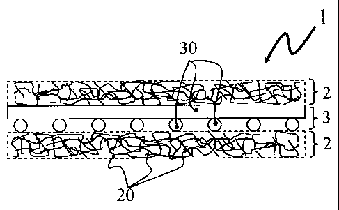
Fig. 1 shows the schematic structural design of a flat
textile structure (1) according to one aspect of the
present invention. The reinforcing grid (3) according to
the invention, as represented by its grid braces (30), is
here secured between two pile layers (2) according to the
invention, as represented by its fibers (20).
Fig. 2 shows the schematic structural design of a preferred
embodiment of the flat textile structure (1) according to
the invention. Two vertically stacked pile layers (2) here
lie on one side of the reinforcing grid (3), while one pile
layer (2) lies on the other side. This embodiment is
preferred because the surface of the flat textile structure
(1) exhibits better optical and tactile characteristics on
the side with the two vertically stacked pile layers (2).
This becomes advantageous when primarily only one side of
the Component is visible in the subsequent component that
integrates the flat textile structure (1), for example in
the case of vehicle doors.
Fig. 3 shows the schematic structural design of an
embodiment of the flat textile structure (1) according to
the invention. Two vertical;y stacked pile layers (2) here
lie on one side of the reinforcing grid (3), while the
other side of the reinforcing grid (3) remains clear. This
embodiment is advantageous in particular when the optical
and tactile requirements relate exclusively to one side of
the flat textile structure (1).
DETAILED DESCRIPTION
The term "pile layer" is known to the expert. It refers to a
loose layer of randomly intertwined single fibers that has not
been solidified, for example through needling.
Methods for manufacturing a pile layer (2) are known to the
expert, for example willowing or carding. Depending
on the
method, the alignments for the single fibers (20) in the
CA 02802296 2012-12-11
=
- 6 -
pile layer (2) are more or less homogenously distributed.
However, the fibers (20) in the pile layer (2) exhibit a
preferred direction in some methods, for example in the
carding method. This means that the alignment of the fibers
(20) in the pile layer (2) is more often encountered in one
specific direction than in other directions. This is
because the fibers (20) are always combed back and forth in
the same direction in the carding process. As a
consequence, the resulting pile layer (2) frequently
exhibits a greater strength longitudinally to the preferred
direction of the fibers (20) than perpendicular thereto. In
the present invention, the term "preferred direction" of
the pile layer (2) must be understood in the light of the
definition provided here.
A "woven" or "woven material" or a "woven layer" or "woven
material layer" refers to a pile layer (2) that has been
solidified, for example through needling.
Methods for solidifying a pile layer (2) into a woven
layer, for example needling, are known to the expert.
Solidification methods can be thermal, mechanical or
chemical in nature. Thermal solidification typically
involves melting open a medium that is already added to the
flat textile structure before the pile is manufactured, for
example. However, mechanical methods encompass needling and
stitching. The chemical method typically involves spraying
on an adhesive. The methods relating to the pile layer (2)
are also applied during the solidification of the flat
textile structure (1) according to the invention. All pile
layers (2) present in the flat textile structure (1) and
the reinforcing grid (3) are here joined together. During
mechanical solidification, this occurs in such a way as to
intertwine the grid braces of the reinforcing grid (3) with
individual fibers of the adjoining pile layers (2), which
yields a stronger connection between the reinforcing grid
(3) and pile layers (2).
CA 02802296 2012-12-11
- 7 -
If the pile layer (2) that was further processed into a
woven exhibits a preferred direction for the fibers (20),
this can often also be discerned from the surface of the
woven material, for example after the pile layer (2) has
been needled.
Within the framework of this invention, the flat textile
structure (1) according to the invention is referred to as
"nonwoven plies" in certain contexts.
In a preferred embodiment of the present invention, the
flat textile structure (1) exhibits a weight per unit area
of 80-110 g/m2, wherein the carbon fibers in the flat
textile structure (1) have a proportionate weight per unit
area of 65 to 84%, and the reinforcing grid (3) has a
proportionate weight per unit area of 3 to 10 g/m2. This
embodiment is especially suited for use in components in
the automotive industry to replace thin metal sheets, for
example engine hoods, doors, fenders, etc.
The reinforcing grid (3) can be located between two
consecutive pile layers (2) inside the flat textile
structure (1). The advantage here is that the desired
optical and tactile composition can be ensured on both
surfaces of the flat textile structure (1).
Aside from that, it can also be advantageous for the
reinforcing grid (3) to be located on the outside of the
flat textile structure (1). Very thin flat textile
structures (1) can here be fabricated, at least one side of
which exhibits the desired optical and tactile composition.
As a result, this embodiment is especially suited for use
in components according to the invention, which as intended
are visible only from one side in the finished product, for
example, vehicle doors.
CA 02802296 2012-12-11
=
- 8 -
According to the invention, the pile layers (2) are
comprised predominantly of carbon fibers. Within the
framework of this invention, the portion that does not
consist of carbon fibers is referred to as the "foreign
fiber portion". Depending on the context, the foreign fiber
portion can relate both to the entire flat textile
structure, as well as only to the pile layer (2). A low
foreign fiber portion is basically desired, since the
stability of the component according to the invention drops
as the foreign fiber portion rises. However, carbon fibers
are very cost-intensive. Therefore, once a sufficient
stability has been reached for the component, foreign
fibers can be added to the fibers to be processed in a
targeted manner, specifically in such a way that the carbon
fibers make up a percentage of the overall weight per unit
area of the flat textile structure (1) according to the
subject matter of the present invention, preferably a
percentage measuring 65 to 84%.
No special limitations are placed on the material and
composition of the reinforcing grid (3). It preferably
consists of threads of endless fibers (30), which are
present as scrims, wovens, knots or knits, wherein scrims
are preferred, since they are the easiest to fabricate, and
exhibit the smallest layer thickness at the intersecting
points by comparison to knits.
For example, the fibers in the reinforcing grid (3) can
consist of polyester, glass, polyamide, polyethylene,
aramide fibers and/or carbon, wherein polyester and glass
represent preferred materials for reasons of cost in
conjunction with the ratio between strength and fiber
thickness.
Regardless of whether the reinforcing grid (3) is comprised
of scrims, wovens, knots or knits, the structural
constituents of the reinforcing grid (3) are referred to as
CA 02802296 2012-12-11
- 9 -
"braces" or "grid braces" and "intersecting points" within
the framework of this invention, in keeping with the
general meaning ascribed to a grid.
The preferred titers for the braces (30) in the reinforcing
grid (3) preferably measure 120 to 350 dtex. Also preferred
are titers between 150 and 280 dtex, since optimal results
are achieved in this range with respect to the strength and
scope of the troughs, which are formed by the meshes of the
reinforcing grid (3) on the surface of the flat textile
structure (1) according to the invention, and a sufficient
draping ability is ensured.
The intersecting points of the reinforcing grid (3) can
exhibit a binding agent. If the reinforcing grid (3) is a
scrim layer, it is preferred that a binding agent be used
at the intersecting points. No special limitations are
placed on the selection of binding agent. However, PVAC-
based binding agents are preferred, since they are hot
sealable, and make it especially easy and inexpensive to
manufacture the reinforcing grid (3).
In terms of structural design, the reinforcing grid (3)
preferably consists of two to three blades of parallel
braces (30). However, more than three blades are also
possible.
If the structural design consists of two blades of parallel
braces (5a), the checkerboard structure (5) is preferred,
i.e., the reinforcing grid (3) exhibits square meshes. Fig.
provides a schematic view depicting a cutout from this
structure. The advantage here has to do with a maximum
isotropy for the strength of the flat structure, meaning
with a directionally independent strength. The distance
between the braces (5a) preferably measures 10 to 50 mm in
this embodiment, more preferably 10 to 18 mm, since the
CA 02802296 2012-12-11
- 10 -
troughs described above are less pronounced given smaller
meshes.
If the structural design consists of three blades of
parallel braces (4a, 4b, 4c), the braces of one blade are
referred to as "longitudinal braces" (4a), and the braces
of the two other blades are referred to as "diagonal
braces" (4b, 4c). Fig. 4 provides a schematic view
depicting a cutout from this structure. Preference here
goes to a structural design in which one blade of diagonal
braces (4b) is situated at an angle greater than 450 and
less than 90 relative to the longitudinal braces (4a),
while these angles are less than -450 and greater than -90
for the other blade of diagonal braces (4c), and the angles
for both blades of diagonal braces (4b, 4c) relative to the
longitudinal braces (4a) are each numerically equal. Viewed
in isolation, the blades of the diagonal braces (4b, 4c)
thus form rhomboid meshes. In this embodiment, the distance
between the longitudinal braces (4a) preferably measures 5
to 20 mm. In this embodiment, the distance between the
diagonal braces (4b, 4c) within a blade preferably measures
7 to 50 mm, since the troughs described above are sparingly
pronounced as a result, while a sufficient strength is
ensured at the same time.
Regardless of how the grid (3) is designed, a blade of
parallel braces (30) of the reinforcing grid (3) is
preferably aligned longitudinally to the preferred
direction of the fibers (20) in the pile layers (2), if
any, while combining the reinforcing grid (3) and pile
layers (2). This helps to simplify the manufacturing
process.
A method for manufacturing the flat textile structure (1)
according to the invention in which the reinforcing grid
(3,) is situated between two consecutive pile layers (2)
CA 02802296 2012-12-11
- 11 -
typically encompasses the same steps, preferably within a
continuous process:
a) Manufacturing a pile layer (2) with the desired weight
per unit area,
b) Manufacturing additional pile layers (2) as needed,
and applying the latter to the pile layer (2)
manufactured in a),
c) Applying the reinforcing grid (3) to the pile layer
(2) manufactured in a), or on the stack of pile layers
(2) manufactured in a) and b), if necessary,
d) Applying at least one additional pile layer (2) on the
reinforcing grid (3) prepared in c),
e) Solidifying the plies placed one on top of the other
in a) to d), for example through needling, and
f) Gathering the flat structure (1) created in e), for
example on a roller.
A method for manufacturing the flat textile structure (1)
according to the invention in which the reinforcing grid
(3) is secured to the outside of the flat textile structure
(1) typically encompasses the following steps, preferably
within a continuous process.
a) Applying at least one pile layer (2) on a reinforcing
grid (3),
b) Solidifying the plies placed one on top of the other
in a), for example through needling, and
c) Gathering the flat structure (1) created in b), for
example on a roller.
CA 02802296 2012-12-11
- 12 -
The term "ply" in conjunction with the method described
above refers to both a pile layer (2) and the reinforcing
grid (3).
In another aspect of the present invention, several plies
of the flat textile structure (1) according to the
invention, hereinafter referred to as "nonwoven plies", can
be flatly joined together, thereby giving rise to the
article according to the invention.
The preferred directions of the individual nonwoven plies
(1), if any, can be aligned parallel to each other.
However, depending on how and where the article is used, it
can also be advantageous to flatly join the nonwoven plies
(1) at different angles to each other with respect to their
preferred direction. One preferred embodiment provides a
composite of three nonwoven plies (1), wherein the
preferred direction of the middle and upper nonwoven ply
(1) is aligned at an angle of 45 or -45 to the preferred
direction of the lower nonwoven ply (1). This yields an
increased isotropy for the strength of the article and
components fabricated from the latter.
For example, the connection between the nonwoven plies (1)
according to the invention can be achieved by simply
stitching them together, or through renewed needling.
However, other types of joining are also possible.
In a preferred embodiment, at least one grid ply can be
provided between two or more nonwoven plies (1) of the
article according to the invention. During the impregnation
process, e.g., while injecting a fluid polymer matrix, for
manufacturing the component according to the invention,
this allows the polymer material to better penetrate into
the complex of several nonwoven plies and optimally
impregnate the latter, without the individual nonwoven
CA 02802296 2012-12-11
- 13 -
plies (1) slipping relative to each other. The grid ply can
be structured based on the reinforcing grid (3) according
to the invention. However, a grid with a different
structural design can also be used. Knits or scrims
consisting of polyester threads are here preferred, since
they are easy and inexpensive to manufacture.
In another aspect of the present invention, the flat
textile structure (1) according to the invention or article
according to the invention is impregnated with a polymer
matrix, leading to the component according to the
invention.
No special limitations are placed on the materials in the
polymer matrix. Suitable materials for the polymer matrix
usually include resins, such as polyester resins, epoxy
resins and vinyl ester resins, which are used in the
manufacture of fiber composite materials.
Suitable methods for impregnating flat textile structures
(1), for example resin injection or infusion methods, are
known to the expert. Subsequent hardening, for example
through exposure to an elevated temperature, yields a
component in the desired form. As a result, it is most
often necessary to drape the flat textile structure (1) on
a rigid mold beforehand. The flat textile structure (1)
according to the invention is here distinguished by an
optimal draping ability due to its configuration.
In another aspect of the present invention, the component
according to the invention is used to manufacture
automobile parts. No special limitations are here placed on
the type and functionality of the components. Non-load
bearing parts are here preferred.
Load-bearing parts in an automobile, such as A, B or C
columns, are highly stressable components. If they consist
CA 02802296 2012-12-11
- 14 -
of fiber composite materials, use is usually made of woven
matting or scrims, wherein the fiber bundles in the woven
matting or scrims are aligned in such a way as to optimally
absorb or divert acting forces, i.e., fiber bundles in the
woven matting of scrims are preferably aligned in the
direction of applied force. In nonwoven materials, the
strength is distributed in all directions owing to the
structure, wherein the preferred directions generated by
combing the pile can again elevate the anisotropy for the
strength of the nonwoven material. This is why fiber
composite materials fabricated out of nonwovens can be used
in highly stressable components of a vehicle. However, the
combined use of nonwoven materials and woven matting or
scrims is also possible, for example in the form of
nonwoven scrim complexes.