Note : Les descriptions sont présentées dans la langue officielle dans laquelle elles ont été soumises.
CA 02802459 2014-10-27
,
,
ADJUSTABLE MOUNTING ASSEMBLY FOR AN ANTENNA MAST
TECHNICAL FIELD
[0001-2] Embodiments of the subject matter described herein relate generally
to
mounting hardware, fixtures, and assemblies suitable for use with antennas.
More
particularly, embodiments of the subject matter relate to an antenna mounting
assembly
having a convenient and easy-to-manipulate adjustment feature.
BACKGROUND
[0003] Direct broadcast satellite (DBS) systems are commonly used
as an alternative
or supplement to traditional cable distribution systems that deliver
television
programming to viewers. A typical DBS system includes a relatively small
satellite
antenna that is located at the viewer site, e.g., a house, an office building,
or a library. To
optimize reception of satellite signals, the antenna structure is often
mounted to a building
or structure such as a rooftop, a wall, an awning, a railing of a deck or
balcony, a pillar, or
the like.
[0004] A DBS antenna structure typically includes a mounting foot,
a mast, and the
antenna assembly itself (which includes the satellite dish component). The
mounting foot
is attached to the desired mounting structure, and the antenna assembly is
attached to the
mounting foot using the mast. In typical configurations, the connection
between the mast
and the mounting foot enables the mast to pivot relative to the mounting foot,
which
accommodates installation of the antenna structure in a variety of locations
and positions.
In this regard, it may be desirable to mount the mast and/or the antenna
assembly in a
certain orientation relative to a vertical reference line (a plumb line).
Accordingly, during
installation of the antenna structure, the mast can be pivoted and adjusted
into the desired
position and then secured in that position.
[0005] Depending upon the specific design of the mast and mounting
foot, adjustment
of the mast into the desired position can be difficult and time consuming.
Indeed, it may
1
CA 02802459 2012-12-12
WO 2011/159450
PCT/US2011/038117
be necessary to involve two or more people to accurately adjust and secure the
mast into
the desired position. Moreover, in some conventional designs the mast-to-foot
joint is
subjected to high torque (due to the length of the mast and the mass of the
antenna
assembly at the end of the mast), which increases under high wind conditions.
Consequently, even if the mast is initially secured to the mounting foot in a
proper
manner, the mast could still "slip" and pivot relative to the mounting foot,
especially if
the antenna assembly is bumped or if the antenna assembly is exposed to high
wind
conditions.
[0006] Accordingly, it is desirable to have an adjustable antenna mounting
assembly
that is easy to adjust and install in the field, that is robust and remains in
the desired
position after deployment, and that otherwise addresses the various
shortcomings of
conventional antenna mounting assemblies.
BRIEF SUMMARY
[0007] An embodiment of a foot assembly for mounting an antenna is provided
here.
The foot assembly generally includes a foot, a first positioning component,
and a second
positioning component. The foot includes a base designed to be attached to a
mounting
structure, a first sidewall flange extending from the base and terminating at
a first distal
section, a first slot formed within the first distal section, a second
sidewall flange
extending from the base and terminating at a second distal section (the second
sidewall
flange opposing the first sidewall flange), and a second slot formed within
the second
distal section (the second slot opposing and aligned with the first slot). The
first
positioning component extends between the first sidewall flange and the second
sidewall
flange, the first positioning component is slidably adjustable within the
first slot and the
second slot, and the first positioning component provides a first support
structure for an
antenna mast. The second positioning component extends between the first
sidewall
flange and the second sidewall flange, the second positioning component is
slidably
adjustable within the first slot and the second slot, and the second
positioning component
provides a second support structure for the antenna mast.
[0008] Also provided is another embodiment of a foot assembly for mounting
an
antenna mast. The foot assembly includes a foot, a first positioning
component, a second
positioning component, and an adjustment assembly. The foot includes: a first
sidewall
flange terminating at a first distal section; a first slot formed within the
first distal section;
a second sidewall flange terminating at a second distal section, the second
sidewall flange
2
CA 02802459 2012-12-12
WO 2011/159450 PCT/US2011/038117
opposing the first sidewall flange; and a second slot formed within the second
distal
section, the second slot opposing and aligned with the first slot. The first
positioning
component is coupled between the first sidewall flange and the second sidewall
flange, it
is configured for sliding movement within the first slot and the second slot,
and it is
configured to bear upon a first external side of the antenna mast. The second
positioning
component is coupled between the first sidewall flange and the second sidewall
flange, it
is configured for sliding movement within the first slot and the second slot,
and it is
configured to bear upon a second external side of the antenna mast. The
adjustment
assembly is to the first positioning component and the second positioning
component, and
it is configured to adjust spacing between the first positioning component and
the second
positioning component.
[0009] An embodiment of a mounting assembly for an antenna is also
provided. The
mounting assembly includes: a foot; an antenna mast; a first mast positioning
component; and a second mast positioning component. The foot includes: a base
configured to be attached to a mounting structure; a first sidewall flange
extending from
the base, the first sidewall flange having a first slot formed therein; and a
second sidewall
flange extending from the base, the second sidewall flange opposing the first
sidewall
flange and having a second slot formed therein. The antenna mast has a
proximal end
pivotally coupled to the foot between the first sidewall flange and the second
sidewall
flange. The first mast positioning component is coupled between the first
sidewall flange
and the second sidewall flange, it is movable within the first slot and the
second slot, and
it provides a first adjustable support structure for a first external side of
the antenna mast.
The second mast positioning component is coupled between the first sidewall
flange and
the second sidewall flange, it is movable within the first slot and the second
slot, and it
provides a second adjustable support structure for a second external side of
the antenna
mast.
[0010] This summary is provided to introduce a selection of concepts in a
simplified
form that are further described below in the detailed description. This
summary is not
intended to identify key features or essential features of the claimed subject
matter, nor is
it intended to be used as an aid in determining the scope of the claimed
subject matter.
BRIEF DESCRIPTION OF THE DRAWINGS
[0011] A more complete understanding of the subject matter may be derived
by
referring to the detailed description and claims when considered in
conjunction with the
3
CA 02802459 2012-12-12
WO 2011/159450
PCT/US2011/038117
following figures, wherein like reference numbers refer to similar elements
throughout
the figures.
[0012] FIG. 1 is a perspective view of an embodiment of an antenna assembly
mounted to a rooftop;
[0013] FIG. 2 is a perspective view of a mounting foot and an antenna mast
of a
conventional antenna assembly;
[0014] FIG. 3 is a perspective view of a mounting foot assembly and an
antenna mast
configured in accordance with an exemplary embodiment;
[0015] FIG. 4 is an exploded perspective view of the mounting foot assembly
shown
in FIG. 3;
[0016] FIG. 5 is a perspective view of the mounting foot assembly shown in
FIG. 3;
and
[0017] FIG. 6 is a side view of the mounting foot assembly shown in FIG. 3.
DETAILED DESCRIPTION
[0018] The following detailed description is merely illustrative in nature
and is not
intended to limit the embodiments of the subject matter or the application and
uses of
such embodiments. As used herein, the word "exemplary" means "serving as an
example, instance, or illustration." Any implementation described herein as
exemplary is
not necessarily to be construed as preferred or advantageous over other
implementations.
Furthermore, there is no intention to be bound by any expressed or implied
theory
presented in the preceding technical field, background, brief summary or the
following
detailed description.
[0019] In addition, certain terminology may also be used in the following
description
for the purpose of reference only, and thus are not intended to be limiting.
For example,
terms such as "upper", "lower", "above", and "below" might refer to directions
in the
drawings to which reference is made. Terms such as "front", "back", "rear",
"side",
"outboard", and "inboard" may be used to describe the orientation and/or
location of
portions of a component within a consistent but arbitrary frame of reference
which is
made clear by reference to the text and the associated drawings describing the
component
under discussion. Such terminology may include the words specifically
mentioned
above, derivatives thereof, and words of similar import. Similarly, the terms
"first",
"second", and other such numerical terms referring to structures do not imply
a sequence
or order unless clearly indicated by the context.
4
CA 02802459 2012-12-12
WO 2011/159450 PCT/US2011/038117
[0020] FIG. 1 is a perspective view of an embodiment of an antenna assembly
100
mounted to a rooftop 102. The antenna assembly 100 generally includes, without
limitation: a mounting foot assembly 104; an antenna mast 106; and an antenna
108. The
mounting foot assembly 104 is attached to the rooftop 102, which represents a
suitable
mounting structure for the antenna assembly 100. The antenna mast 106 has a
proximal
end 110 that is pivotally coupled to the mounting foot assembly 104 in the
manner
described in more detail below. This pivoting joint facilitates adjustment of
the angle of
the antenna mast 106 relative to the mounting foot assembly 104. Although the
mounting
foot assembly 104 and the antenna mast 106 could be suitably configured to
pivot, rotate,
and/or swivel in any number of directions, the embodiment described here
accommodates
pivoting of the antenna mast 106 substantially in one plane (as indicated by
the arrows
112 in FIG. 1).
[0021] The antenna mast 106 has a distal end 114 to which the antenna 108
is
coupled. In some embodiments, the antenna 108 is coupled to the antenna mast
106 such
that the antenna 108 can pivot, rotate, swivel, or be otherwise adjusted
relative to the
distal end 114 of the antenna mast 106. The antenna 108 may include one or
more
components assembled together, e.g., a dish 116 and a low noise block feed
118. The
antenna 108 is typically installed onto the antenna mast 106 after the
mounting foot
assembly 104 has been attached to the mounting structure (the rooftop 102 in
this
example) and after the antenna mast 106 has been adjusted and secured in the
desired
position. In this regard, the adjustment capabilities of the mounting foot
assembly 104
allow the installer to adjust (pivot) the antenna mast 106 relative to the
mounting foot
assembly 104, and thereafter secure and fix the antenna mast 106 in the
desired position.
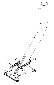
[0022] FIG. 2 is a perspective view of a mounting foot assembly 200 and an
antenna
mast 202 of a conventional antenna assembly. The antenna mast 202 is coupled
to the
mounting foot assembly 200 using one through bolt 204 and two carriage bolts
206 (only
one of which is visible in FIG. 2). The through bolt 204 corresponds to the
axis of
rotation of the antenna mast 202 relative to the mounting foot assembly 200.
The carriage
bolts 206 are inserted through two C-shaped slots 208 (only one of which is
visible in
FIG. 2) and through a corresponding hole located at the end of the antenna
mast 202.
This arrangement allows the antenna mast 202 to pivot about the upper through
bolt 204
throughout the range defined by the slots 208. Thus, a technician can
manipulate the
antenna mast 202 into the desired position and tighten the nuts 210 to "lock"
the antenna
mast 202 in place. Notably, the antenna mast 202 is held in place by the
friction and
CA 02802459 2012-12-12
WO 2011/159450 PCT/US2011/038117
force imparted against the antenna mast 202. In other words, the through bolt
204 and the
carriage bolts 206 are tightened such that flanges of the mounting foot
assembly 200
squeeze the sides of the antenna mast 202. Although this adjustment feature is
simple and
effective, adjustment of the antenna mast 202 can be cumbersome and time
consuming.
Moreover, the antenna mast 202 might shift if one or both nuts 210 become
loose and/or
if the antenna (not shown in FIG. 2) is subjected to high wind conditions.
[0023] The antenna assembly described in more detail below employs an
improved
mast adjustment feature that makes it easier for an installer to adjust and
secure the
antenna mast in the desired position relative to the mounting foot assembly.
Moreover,
certain embodiments of the antenna assembly described here utilize a "fine
adjustment"
mechanism for the antenna mast. The mounting foot assembly presented here is
suitably
configured to maintain the antenna mast in the desired position even under
high wind
conditions. As described in more detail below, the mounting foot assembly does
not
solely rely on friction and compressive force to hold the antenna mast in
place.
[0024] FIG. 3 is a perspective view of a mounting foot assembly 300 and an
antenna
mast 302 configured in accordance with an exemplary embodiment, FIG. 4 is an
exploded
perspective view of the mounting foot assembly 300, FIG. 5 is an enlarged
perspective
view of the mounting foot assembly 300, and FIG. 6 is a side view of the
mounting foot
assembly 300. The combination of the mounting foot assembly 300 and the
antenna mast
302 may be referred to herein as a "mounting assembly" for an antenna (not
shown in
FIGS. 3-6). As explained previously with reference to FIG. 1, an antenna can
be coupled
to the antenna mast 302 in a conventional manner if so desired.
[0025] The illustrated embodiment of the mounting foot assembly 300
generally
includes, without limitation: a foot 304; a front positioning component 306; a
rear
positioning component 308; a coupling element 310; and an adjustment assembly
312.
The foot 304 is formed from a strong, tough, and rigid material such as metal,
a
composite material, reinforced plastic, or the like. In certain embodiments,
the foot 304 is
fabricated as a one-piece integrated component having the desired shape,
features,
mounting holes, physical properties, and characteristics. For example, the
foot 304 may
be formed as a stamped metal (e.g., stainless steel) component, a forged metal
component, a machined metal component, or a molded composite component.
[0026] Referring to FIGS. 4-6, the foot 304 includes, without limitation: a
base 314;
a first sidewall flange 316 extending from the base 314; and a second sidewall
flange 318
extending from the base 314. Although not always required, the base 314 is
typically flat
6
CA 02802459 2012-12-12
WO 2011/159450 PCT/US2011/038117
to accommodate easy attachment to a flat mounting structure such as a rooftop,
a deck, a
wall, or the like. Alternatively, the base 314 could be curved or otherwise
contoured to
facilitate attachment to mounting structures that are not flat. The first
sidewall flange 316
terminates at a respective distal section 320 having a first slot 322 formed
therein, and the
second sidewall flange 318 terminates at a respective distal section 324
having a second
slot 326 formed therein. Although not always required, the sidewall flanges
316, 318 are
generally planar and parallel to one another. Accordingly, the sidewall
flanges 316, 318
oppose one another and are spaced apart to accommodate the antenna mast 302
therebetween.
[0027] The slots 322, 326 oppose one another and are preferably aligned
with one
another. In other words, when viewed from the side, the slots 322, 326
correspond to one
another, as depicted in FIG. 6. For this particular embodiment, the slots 322,
326 are
straight (rather than curved) and are parallel to the major plane defined by
the base 314.
The longitudinal dimension or length of the slots 322, 326 is selected to
accommodate the
desired angular adjustment range of the antenna mast 302. For this particular
example,
the distal sections 320, 324 extend (in the fore and aft directions) beyond
the major
surfaces defined by the respective sidewall flanges 316, 318, as best shown in
FIG. 6.
These extended distal sections 320, 324 accommodate the desired length of the
slots 322,
326, which is slightly less than the fore-aft length of the base 314.
[0028] The front positioning component 306 is coupled between the sidewall
flanges
316, 318, and it is slidably adjustable within the slots 322, 326. The front
positioning
component 306 provides a front support structure for the antenna mast 302, and
the front
positioning component 306 is configured for sliding movement within the slots
322, 326
to accommodate angular adjustment of the antenna mast 302. As shown in FIG. 5,
at
least one element of the front positioning component 306 contacts, bears upon,
or rests
against the front or forward-facing external side 328 of the antenna mast 302.
Notably, if
the adjustable front positioning component 306 is locked in the position shown
in FIG. 5
and FIG. 6, it will inhibit or impede forward pivoting of the antenna mast
302.
[0029] Although not always required, the illustrated embodiment of the
front
positioning component 306 includes, without limitation: a sleeve bushing 330;
a bolt
332; and a nut 334 (see FIG. 4). The bolt 332 is inserted through the slot
322, through the
sleeve bushing 330 (which is located between the sidewall flanges 316, 318),
and through
the slot 326. At least the end of the bolt 332 is threaded to accommodate the
nut 334,
which engages the threaded end of the bolt 332. Thus, the nut 334 can be
loosened to
7
CA 02802459 2012-12-12
WO 2011/159450 PCT/US2011/038117
enable the front positioning component 306 to slide within the slots 322, 326,
and the nut
334 can be tightened to secure and fix the front positioning component 306 in
its desired
fore-aft position on the foot assembly 300.
[0030] The sleeve bushing 330 is fabricated from a strong, rigid, and tough
material,
such as metal. In certain embodiments, the sleeve bushing 330 is formed as a
steel
casting. Notably, the sleeve bushing 330 is sized such that its length (along
its major
longitudinal axis) is equal to or slightly less than the outer width of the
antenna mast 302.
This sizing is desirable to inhibit inward deflection of the sidewall flanges
316, 318
during installation, such that the antenna mast 302 does not get severely bent
or crushed
when the nut 334 is tightened.
[0031] The rear positioning component 308 is also coupled between the
sidewall
flanges 316, 318, and it is slidably adjustable within the slots 322, 326. The
rear
positioning component 308 provides a rear support structure for the antenna
mast 302,
and the rear positioning component 308 is configured for sliding movement
within the
slots 322, 326 to accommodate angular adjustment of the antenna mast 302. As
shown in
FIG. 5, at least one element of the rear positioning component 308 contacts,
bears upon,
or rests against the rear or backward-facing external side 336 of the antenna
mast 302.
Notably, if the adjustable rear positioning component 308 is locked in the
position shown
in FIG. 5 and FIG. 6, it will inhibit or impede backward pivoting of the
antenna mast 302.
[0032] Although not always required, the illustrated embodiment of the rear
positioning component 308 includes, without limitation: a sleeve bushing 338;
a bolt
340; and a nut 342 (see FIG. 4). The bolt 340 is inserted through the slot
322, through the
sleeve bushing 338 (which is located between the sidewall flanges 316, 318),
and through
the slot 326. At least the end of the bolt 340 is threaded to accommodate the
nut 342,
which engages the threaded end of the bolt 340. Thus, the nut 342 can be
loosened to
enable the rear positioning component 308 to slide within the slots 322, 326,
and the nut
342 can be tightened to secure and fix the rear positioning component 308 in
its desired
fore-aft position on the foot assembly 300.
[0033] The sleeve bushing 338 is fabricated from a strong, rigid, and tough
material,
such as metal. In certain embodiments, the sleeve bushing 338 is formed as a
steel
casting. Notably, the sleeve bushing 338 is sized such that its length (along
its major
longitudinal axis) is equal to or slightly less than the outer width of the
antenna mast 302.
This sizing is desirable to inhibit inward deflection of the sidewall flanges
316, 318
8
CA 02802459 2012-12-12
WO 2011/159450 PCT/US2011/038117
during installation, such that the antenna mast 302 does not get severely bent
or crushed
when the nut 342 is tightened.
[0034] The coupling element 310 is used to couple the proximal end 344 of
the
antenna mast 302 (see FIG. 4) to the foot 304 such that the antenna mast 302
is pivotable
relative to the foot 304. Thus, the coupling element 310 corresponds to the
axis of
rotation of the antenna mast 302 relative to the foot 304. Although not always
required,
the coupling element 310 in this particular embodiment is realized as a bolt
(or other
suitable fastener) that extends between the two sidewall flanges 316, 318. In
this regard,
the mounting foot assembly 300 may include a nut 346 that can be threadably
coupled to
the coupling element 310. The coupling element 310 is inserted through a first
hole 348
formed within the first sidewall flange 316, through two holes 349 (only one
of which is
visible in FIG. 4) formed in the proximal end 344 of the antenna mast 302, and
through a
second hole 350 formed within the second sidewall flange 318. As shown in FIG.
5, the
antenna mast 302 is positioned between the sidewall flanges 316, 318 before
the coupling
element 310 is installed.
[0035] As depicted in FIG. 5 and FIG. 6, the front positioning component
306 and the
rear positioning component 308 are designed to flank the antenna mast 302 to
hold the
antenna mast 302 in position relative to the foot 304. In this regard, the
front positioning
component 306 and the rear positioning component 308 are slidably adjustable
relative to
each other to define a mast adjustment distance therebetween. Although the
mast
adjustment distance can be taken between any two reference points, FIG. 6
shows a
distance (d) defined between the longitudinal centers of the bolts 332, 340.
It should be
appreciated that this mast adjustment distance (or the spacing between the
front
positioning component 306 and the rear positioning component 308) corresponds
to or
otherwise influences the mounting angle of the antenna mast 302 relative to
the base 314
of the foot 304. Thus, if the antenna mast 302 depicted in FIG. 6 is to be
pivoted forward
(i.e., closer to forming a ninety degree angle with the base 314), then the
front positioning
component 306 and the rear positioning component 308 will be loosened to
accommodate
forward pivoting of the antenna mast 302. Thereafter, the front positioning
component
306 and the rear positioning component 308 will be moved closer together to
reduce the
mast adjustment distance. Thereafter, the front positioning component 306 and
the rear
positioning component 308 will be tightened to hold the antenna mast 302 in
its new
position.
9
CA 02802459 2012-12-12
WO 2011/159450 PCT/US2011/038117
[0036] As explained above, the location of the positioning components 306,
308 can
be selected in accordance with the desired angular orientation of the antenna
mast 302. In
practice, the positioning components 306, 308 could be manually positioned and
secured.
The adjustment assembly 312 (which is a preferred, but optional, feature of
the mounting
foot assembly 300) can be used as a "fine adjustment" mechanism for the
antenna mast
302. The adjustment assembly 312 includes one or more elements that are
coupled to the
front positioning component 306 and to the rear positioning component 308, and
actuation or manipulation of the adjustment assembly 312 changes the spacing
between
the front positioning component 306 and the rear positioning component 308.
[0037] For the illustrated embodiment, the adjustment assembly 312
includes, without
limitation: an adjustment bolt 360; a front boss 362 or other suitably
configured structure
coupled to or integrated with the front sleeve bushing 330; and a rear boss
364 or other
suitably configured structure coupled to or integrated with the rear sleeve
bushing 338.
The front boss 362 has a threaded through hole 366 formed therein, and the
rear boss 364
has an unthreaded through hole 368 formed therein. This arrangement
accommodates
coupling of the adjustment bolt 360 (and/or the adjustment assembly 312
itself) to the
sleeve bushings 330, 338. As shown in FIG. 5 and FIG. 6, the major
longitudinal axis of
the sleeve bushing 330 is orthogonal to the adjustment bolt 360, and the major
longitudinal axis of the sleeve bushing 338 is orthogonal to the adjustment
bolt 360. This
arrangement facilitates easy and efficient adjustment of the positioning
components 306,
308 within the slots 322, 326, which are parallel to the adjustment bolt 360.
[0038] The threaded through hole 366 has threads that mate with
corresponding
threads of the adjustment bolt 360. When the mounting foot assembly 300 is
assembled,
the adjustment bolt 360 is positioned in the unthreaded through hole 368 and
is engaged
with the threaded through hole 366 (see FIG. 6). The adjustment bolt 360
passes through
two slots 370 formed in the proximal end 344 of the antenna mast 302 (only one
slot 370
is visible in FIG. 4). Rotation of the adjustment bolt 360 in the clockwise
direction (i.e.,
"tightening") decreases the spacing between the positioning components 306,
308, due to
the threaded engagement with the front boss 362. In contrast, rotation of the
adjustment
bolt 360 in the counterclockwise direction (i.e., "loosening") increases the
spacing
between the positioning components 306, 308.
[0039] It should be appreciated that the adjustment assembly 312 could be
designed
in an alternate manner while preserving its adjustment capabilities. For
example, both the
front boss 362 and the rear boss 364 could be threaded (in opposite
directions) such that
CA 02802459 2012-12-12
WO 2011/159450
PCT/US2011/038117
rotation of the adjustment bolt 360 results in movement of both sleeve
bushings 330, 338
relative to the adjustment bolt 360. As another example, two or more separate
and
distinct adjustment bolts (or other actuators) could be deployed to adjust the
sleeve
bushings 330, 338. As yet another example, another "level" of positioning
components
and corresponding slots could be deployed above and/or below the positioning
components 306, 308 to enhance the structural integrity of the mounting foot
assembly
300.
[0040] In the field, an antenna assembly can be installed using the
mounting foot
assembly 300 in the following manner. After the desired location of the
antenna
assembly has been determined, the mounting foot assembly 300 is attached to
the
mounting structure via the foot 304. Referring to FIG. 3, in most
installations it is
desirable to have the straight distal end 380 of the antenna mast 302 as close
to plumb
(vertical) as possible. Thus, the installer will adjust the angle of the
antenna mast 302 as
needed until the distal end 380 is approximately vertical. The positioning
components
306, 308 can then be partially tightened such that the antenna mast 302 does
not move on
its own accord. Thereafter, the installer can "fine tune" the angle of the
antenna mast 302
by actuating the adjustment bolt 360 while manipulating the antenna mast 302
if
necessary. After adjusting the position of the antenna mast 302, the
positioning
components 306, 308 are completely tightened to secure them and "lock" the
antenna
mast 302 in position. Thereafter, the remainder of the antenna assembly can be
attached
to the distal end 380 of the antenna mast 302, and installation can be
completed in a
conventional manner.
[0041] While at least one exemplary embodiment has been presented in the
foregoing
detailed description, it should be appreciated that a vast number of
variations exist. It
should also be appreciated that the exemplary embodiment or embodiments
described
herein are not intended to limit the scope, applicability, or configuration of
the claimed
subject matter in any way. Rather, the foregoing detailed description will
provide those
skilled in the art with a convenient road map for implementing the described
embodiment
or embodiments. It should be understood that various changes can be made in
the
function and arrangement of elements without departing from the scope defined
by the
claims, which includes known equivalents and foreseeable equivalents at the
time of
filing this patent application.
11