Note : Les descriptions sont présentées dans la langue officielle dans laquelle elles ont été soumises.
CA 02802712 2012-12-13
WO 2011/160069 PCT/US2011/040960
PUMP CAVITATION DEVICE
Cross-Reference to Related Application
This application claims priority to provisional patent application S.N.
61/355,878,
filed June 17, 2010.
1
CA 02802712 2012-12-13
WO 2011/160069 PCT/US2011/040960
Technical Field
This disclosure relates in general to pumps and in particular to a sacrificial
body that
mitigates pitting and corrosion due to cavitation.
-2-
CA 02802712 2012-12-13
WO 2011/160069 PCT/US2011/040960
Background of the Disclosure
Cavitation in pumping devices causes early failure of components due to
erosion/corrosion and the resulting pitting. The pitting causes several
problems: leaks in
sealing areas, loss of pressure integrity, or loss of pressure integrity due
to sudden
catastrophic failure from a crack in the pressure chamber that begins at a
cavitation corrosion
pit and rapidly propagates through the pressure containing wall of the pumping
chamber.
Cavitation usually initiates in predictable places such as, but not limited
to, near the edge of a
sealing surface, areas where there is a sudden drop in pressure that produces
turbulent fluid
flow, or at microscopic discontinuities in the surface of the metal grain and
composition
properties.
Cavitation occurs when there is a rapid drop in pressure in areas of
turbulence,
particularly at the beginning of the suction stroke on a reciprocating pump or
on the trailing
edge of an impeller style centrifugal pump. Small air bubbles are formed and
the collapsing
of the bubbles can reach boundary velocities high enough to erode the metal
away, causing
pitting. During the formation and collapse of these bubbles chemical changes
also occur, due
to the rapid phase change from a liquid to gas, and back from a gas to liquid
which
propagates the release of hydrogen ions. These hydrogen ions have a corrosive
effect on the
molecular structure of the metal, causing small particles of the metal to
separate and enter
into the fluid stream, contributing to further acceleration of the pitting
process. These
hydrogen ions cause the formation of hydrogen embrittlement cracks, which
propagate during
each pumping stroke of a reciprocating pump. Eventually this cracking begins
to penetrate
into the pressure containing wall and rapidly results in a structural failure
of the pressure
vessel.
In applications where a lot of fluid is pumped at high velocities, the
maintenance costs
due to cavitation erosion/corrosion can be a significant part of the operating
costs.
-3-
CA 02802712 2012-12-13
WO 2011/160069 PCT/US2011/040960
Eliminating cavitation is unrealistic due to the high pressures and rapid flow
rates needed in
many industries. An industry that experiences high costs of "expendables" is
the well service
frac industry. Due to governmental limitations on the weight and the width of
vehicles that
are allowed highway access, frac trucks used in the well service frac industry
are made as
light and as small as possible while still being able to achieve the pumping
pressures and flow
required. Designed to be as light as possible, the fluid end and its internal
components of the
pumps associated with such well service equipment can wear and fail quickly,
due to erosion
and corrosion. When pitting occurs in the pumping chamber of the fluid end,
the stresses
concentrate in the pit with the result that corrosion cracking is initiated
and results in the
failure of the fluid end to hold pressure. Replacing of fluid ends is one of
the highest
maintenance costs of the well service frac business. Obtaining a longer
lasting fluid end and
longer lasting valves, seats and packing is an important objective of this
industry. Efforts are
commonly made to either reduce the cavitation or to select materials that are
more resistant to
cavitation erosion and corrosion. Valves, seats and packing are also destroyed
quickly due to
erosion and corrosion, which are accelerated when cavitation occurs. Slowing
the pump
speed down can mitigate this problem, but due to the competitive nature of the
business, and
the demand for higher pressure operations, the pumps are run at high speeds,
and cavitation is
unavoidable at these speeds.
Raising the supercharge pressure to the inlet of the pump may reduce
cavitation.
Using a properly sized suction pulsation device can reduce cavitation. But
with these
solutions implemented in the industry, and with cavitation erosion/corrosion
still causing
expensive maintenance issues, the demand continues for equipment that will
last longer so
that operating costs can be further reduced.
-4-
CA 02802712 2012-12-13
WO 2011/160069 PCT/US2011/040960
Summary
In a first aspect, embodiments are disclosed of a method that reduces
cavitation
damage to a component within a pump including mounting a sacrificial body
within the pump
and operating the pump to pump fluid at a rate that causes at least some
cavitation to occur on
the component, wherein the pumped fluid flows over the sacrificial body to
shed electrons
into the flowing fluid in the vicinity of the cavitation. Since the cavitation
damage of a
component having a sacrificial member is reduced as compared to component not
having a
sacrificial body, the sacrificial member advantageously extends the working
life of the
component beyond a component not having a sacrificial body mounted therein.
In certain embodiments, the sacrificial body includes a material that is more
easily
corroded than the component within a pump.
In yet other embodiments, during use, the operating step causes hydrogen ions
to
release from the component within the pump, the release of which is mitigated
by the
shedding of electrons from the sacrificial body.
In certain embodiments, the method includes attaching at least one needle to
the
sacrificial body to facilitate the shedding of electrons from the sacrificial
body.
In other embodiments, in use the needle is pointing downstream.
In certain embodiments, the needle is formed of a metal that is less subject
to
corrosion than the sacrificial body.
In certain embodiments, the method further comprises the step of mounting an
upstream portion of the sacrificial body into the pump, the sacrificial body
having a profile to
enhance turbulence of the fluid flowing over the sacrificial body.
In certain embodiments, the pump is positioned such that no portion of the
pump is
immersed in the fluid to be pumped by the pump.
-5-
CA 02802712 2012-12-13
WO 2011/160069 PCT/US2011/040960
In certain embodiments, the sacrificial body is formed from one or more
materials
from the group comprising zinc, aluminum, magnesium or alloys thereof.
In certain embodiments, the turbulence created from mounting the sacrificial
body in
the component produces cavitation on a surface of the sacrificial body rather
than allowing
the cavitation bubbles to form on the component. The amount of purposely
created cavitation
bubbles and the resulting deterioration of the sacrificial body is related to
the energy needed
to overcome the energy consumed as a gas phase changes to a liquid and a
liquid phase
changes back to a gas during cavitation. The energy of the phase change
demands the release
of hydrogen ions, which is a corrosion phenomenon. The sacrificial body is
made from
materials that more readily release ions than does the steel of the fluid
chamber; which directs
the damaging cavitation corrosion pitting to the sacrificial body.
In yet another embodiment, the component includes a fluid end block having a
chamber, a plunger bore leading to the chamber, a suction valve port leading
to the chamber,
and a discharge valve port passing from the chamber.
In certain embodiments, the method includes mounting the sacrificial body
within the
chamber.
In certain embodiments, the method includes mounting the sacrificial body
stationarily within the plunger bore surrounding the plunger.
In certain embodiments, the method includes mounting the sacrificial body to
the
suction valve for movement therewith.
In certain embodiments, the method includes mounting the sacrificial body
within the
suction valve port upstream from a suction valve.
In another embodiment, the component includes a plunger in the plunger bore.
In yet another embodiment, the mounting step includes mounting a sacrificial
body to
the plunger.
-6-
CA 02802712 2012-12-13
WO 2011/160069 PCT/US2011/040960
In certain of the embodiments, the component includes a housing having a
rotatable
impeller therein.
In certain of the embodiments, the method includes mounting the sacrificial
body
within the housing adjacent a periphery of the impeller.
In certain of the embodiments, the method includes mounting the sacrificial
body to
the impeller for rotation therewith.
In a second aspect, an embodiment is disclosed of a pump having a fluid end
block
containing a chamber, a plunger bore leading to the chamber, a suction valve
port leading to
the chamber, and a discharge valve port passing from the chamber. The suction
and
discharge valves are mounted for reciprocation within the suction valve port
and discharge
valve port, respectively. A sacrificial body is mounted within the fluid end
block for
immersion during use in the fluid flow as the plunger strokes. The sacrificial
body is formed
of a material less resistant to corrosion as compared to the fluid end block.
The embodiment
advantageously provides a pump having a targeted area of cavitation to
mitigate cavitation on
the fluid end block, which extends the working life of the fluid end block.
Moreover, the
sacrificial member targeted for cavitation can be replaced over the life of
the fluid end block.
In certain embodiments, at least one needle is mounted to the sacrificial
body, the
needle in use being immersed in the flowing fluid and pointing in a downstream
direction.
In certain embodiments, the needle is formed of a metal more resistant to
corrosion
due to the fluid flowing over the needle than the sacrificial body.
In certain of the embodiments, a profile configured to enhance turbulence is
located
on an upstream portion of the sacrificial body.
In certain embodiments, the sacrificial body is formed from one or more
materials
from the group comprising zinc, aluminum, magnesium or alloys thereof.
-7-
CA 02802712 2012-12-13
WO 2011/160069 PCT/US2011/040960
In certain of the embodiments, the sacrificial body includes a sleeve mounted
stationarily within the plunger bore surrounding the plunger.
In certain of the embodiments, the sacrificial body is mounted to a forward
end of the
plunger for movement therewith.
In certain of the embodiments, the sacrificial body is mounted to the suction
valve for
movement therewith.
In certain of the embodiments, the sacrificial body is mounted within the
suction
valve port upstream from the suction valve.
In a third aspect, an embodiment is disclosed of a pump including a housing, a
rotatable impeller mounted within the housing, and a sacrificial body mounted
within the
housing for immersion within fluid flow as the impeller rotates during use.
The sacrificial
body formed of a material less resistant to corrosion due to the fluid flow
than the impeller
and the housing.
In certain of the embodiments, the sacrificial body is mounted to an interior
portion of
the housing adjacent a periphery of the impeller.
In certain of the embodiments, the sacrificial body is mounted to the impeller
for
rotation therewith.
In a fourth aspect, an embodiment is disclosed of an apparatus for retarding
damage to
a pump due to cavitation including a sacrificial body adapted to be mounted
within the pump,
the sacrificial body being formed of a material selected to shed electrons
when immersed
within a flowing fluid of the pump. At least one needle is mounted to the
sacrificial body and
formed of a material more resistant to corrosion due to the flowing fluid than
the sacrificial
body.
-8-
CA 02802712 2012-12-13
WO 2011/160069 PCT/US2011/040960
In certain embodiments, the sacrificial body includes a sleeve having a
profile formed
on an exterior surface to enhance turbulence of fluid flowing over the sleeve,
the profile
adapted to be upstream of the at least one needle.
In certain embodiments, the sacrificial body includes a disk having a circular
periphery and adapted to be mounted to an inner end of a plunger of the pump.
The needle is
mounted to a face of the disk in alignment with an axis of the disk.
In certain embodiments, the needle is recessed within a cavity formed in the
face of
the disk. A flow port extends through a portion of the disk to a base of the
cavity for
directing fluid to the needle.
In certain embodiments, the sacrificial body includes a ring adapted to be
mounted to
a downstream face of a suction valve of the pump. The needle is mounted to the
face of the
ring in alignment with an axis of the ring.
In certain embodiments, a flow port leads from one side of the ring to the
face of the
ring adjacent the needle, the flow port being outboard of an inner diameter of
the ring.
In certain embodiments, the sacrificial body is mounted on a support rod. The
support
rod adapted to be mounted to an interior portion of the pump.
In certain of the embodiments, the sacrificial body is formed from of a
material from
the group consisting of zinc, aluminum, magnesium or alloys thereof.
Other aspects, features, and advantages will become apparent from the
following
detailed description when taken in conjunction with the accompanying drawings,
which are a
part of this disclosure and which illustrate, by way of example, the
principles disclosed.
-9-
CA 02802712 2012-12-13
WO 2011/160069 PCT/US2011/040960
Description of the Figures
The accompanying drawings facilitate an understanding of the various
embodiments.
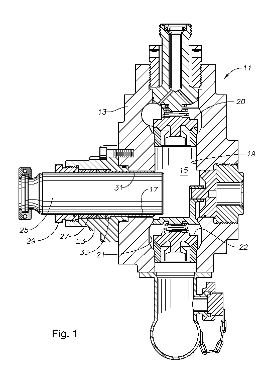
Figure 1 is sectional view of a fluid end of a reciprocating frac pump having
a
cavitation device in accordance with this disclosure.
Figure 2 is an enlarged sectional view of a portion of the cavitation device
of
Figure 1.
Figure 3 is a sectional view of a fluid end of a reciprocating pump having a
second
embodiment of a cavitation device.
Figure 4 is an enlarged sectional view of a portion of the cavitation device
of
Figure 3.
Figure 5 is a sectional view of a fluid end of a reciprocating pump having
another
embodiment of a cavitation device.
Figure 6 is an enlarged sectional view of a portion of the cavitation device
of
Figure 5.
Figure 7 is a sectional view of a fluid end of a reciprocating pump having
another
embodiment of a cavitation device.
Figure 8 is an enlarged sectional view of a portion of the cavitation device
of
Figure 7.
Figure 9 is a schematic view illustrating a centrifugal pump having a
cavitation device
in accordance with this disclosure.
Figure 10 is a schematic view of a centrifugal pump having another embodiment
of a
cavitation device in accordance with this disclosure.
-10-
CA 02802712 2012-12-13
WO 2011/160069 PCT/US2011/040960
Detailed Description
Referring to Figure 1, a fluid end 11 illustrates one portion of a
reciprocating pump of
a type that is typically used in the well frac industry. The fluid end 11 is
part of a surface
mounted pump, typically mounted on a truck. The fluid end 11 is not submersed
in the fluid
to be pumped; rather a flowline leads to the fluid 11 to convey it to be
pumped. The fluid end
11 includes a fluid end block 13 having a chamber 15. A plunger bore 17
intersects the
chamber 15 on one side. A discharge valve port or passage 19 leads from the
chamber 15; a
suction on inlet port or passage 21 leads from the chamber 15 in a generally
opposite
direction. In this embodiment, the discharge and suction passages 19 and 21
are coaxial and
perpendicular to the plunger bore 17, but they could be at different angles
relative to each
other and to the plunger bore 17.
A discharge valve 20 is shown located in the discharge passage 19. The
discharge
valve 20 is spring-biased to a closed position, and will open when the
pressure in the chamber
15 is sufficiently high. A suction valve 22 is located in the suction passage
21. The suction
valve 22 is biased to a closed position and will open when the pressure
differential of the
intake pressure over the pressure in the chamber 15 is sufficient to overcome
the bias of the
spring and allow fluid to be admitted to the chamber 15.
A flange connector 23 secures to the fluid end block 13 on one side around the
plunger bore 17. A plunger 25 reciprocates within the flange connector 23 and
the plunger
bore 17 and strokes between an outer intake position and an inner discharge
position by a
conventional power source (not shown). A seal or packing assembly 27 is
located in the
flange connector 23 and sealingly engages the outer diameter of the plunger
25. A packing
nut 29 secures to internal threads at the outer end of the flange connector
23. The packing
nut 29, when rotated, preloads the packing 27 to provide a seal for the
plunger 25. Normally,
-11-
CA 02802712 2012-12-13
WO 2011/160069 PCT/US2011/040960
the fluid end block 13 will have three or five of the chambers 15, plungers
25, and sets of
valves 20 and 22.
A device is shown for retarding the effects of cavitation includes a
sacrificial body in
the form of a sleeve 31, which surrounds the plunger 25 and fits stationarily
within the bore
of the flange connector 23 and the plunger bore 17. As shown in Figure 2, the
sleeve 31 has
an inner diameter with a turbulence enhancing profile including one or more
grooves 35 or
other shapes that can disrupt laminar flow of fluid. In this example, the
groove 35 is helical.
The inner diameter of the sleeve 31 optionally may be in sliding contact with
the outer
diameter of the plunger 25. In this example, the sleeve 31 has an external
flange 33 on its
outer end that mates with a shoulder within the flange connector 23. The inner
end or rim 40
of the sleeve 31 may be substantially flush with the inside wall of the
chamber 15.
Consequently, when the plunger 25 is in the full power stroke position, which
will be to the
right of the position shown in Figure 1, the inner end of the plunger 25 will
be protruding
farther into the chamber 15 than the rim 40 of the sleeve 31.
Referring still to Figure 2, bypass ports 37 extend through the sidewall of
the sleeve
31. The inner end of each of the bypass ports 37 intersects one turn of the
helical groove 35.
The bypass ports 37 are spaced circumferentially around the sleeve 31 and
along a portion of
the length of the sleeve 31. In this embodiment, the outer diameter of the
sleeve 31 is smaller
than the inner diameter of the plunger bore 17, creating an annulus
surrounding the sleeve 31.
This arrangement causes some of the fluid being pushed by the plunger 25
during the inward
or power stroke to flow through the bypass ports 37 and into the annulus
between the outer
diameter of the sleeve 31 and the plunger bore 17. A turbulence creating
profile 38 on the
outer diameter of the sleeve 31 may also include a helical groove or other
shapes. The helical
groove 35 and the ports 37 enhance turbulence and cause cavitation to occur in
the annulus
during the power stroke.
-12-
CA 02802712 2012-12-13
WO 2011/160069 PCT/US2011/040960
The sacrificial body includes a number of needles 39 (only one shown) mounted
around rim 40 of the sleeve 31. The turbulent fluid flowing out the annulus
during the power
stroke flows around them. Each of the needles 39 has a sharp tip and protrudes
inward or
downstream from the rim 40 into the chamber 15 (Fig. 1). Each of the needles
39 may be
parallel to the axis of the plunger bore 17.
The sleeve 31 is a sacrificial body formed of a material or materials that has
characteristics for easily releasing electrons. The material may be, for
example, zinc,
aluminum, magnesium or alloys of these metals. This material is of a less
noble metal than
the fluid end block 13, which is formed of a steel alloy. The material of the
sleeve 31 has a
lower electrochemical potential than the steel alloy of the fluid end block
13, thus the sleeve
31 will corrode more easily due to fluid flowing over it.
The needles 39 can be made of a metal more resistant than the metal of the
sleeve 31
to mitigate corrosion and pitting of the needles. Thus the needles 39 will be
of a material
with a higher electrochemical potential than the sleeve 31. For example, the
needles 39 may
be formed of stainless steel. The metal of the base of each of the needles 39
will be in
contact with the metal of the sleeve 31 such that the needles 39 and the
sleeve 31 serve to
shed or emit electrons from the sleeve 31 into the fluid flowing past the
needles 39.
As mentioned, the sleeve 31 may have profiles to enhance cavitation, causing
the
formation and collapse of bubbles which, if unchecked, can result in chemical
changes of the
steel components, particularly the release of hydrogen ions. Hydrogen ions
have a corrosive
effect on the molecular structure of the metal of the fluid end block 13,
causing small
particles of the metal to separate and enter the fluid stream. This release of
metal particles
contributes to pitting. The release of negatively-charged electrons from the
needles 39
mitigates the formation of hydrogen ions, which are also negatively charged.
Because of the
cavitation, erosion and corrosion will occur on the sleeve 31; however, it is
intended to be
-13-
CA 02802712 2012-12-13
WO 2011/160069 PCT/US2011/040960
expendable. The sleeve 31 is not connected to any voltage potential, rather
releases electrons
as a result of the turbulent fluid flowing over it.
Referring to Figures 3 and 4, in this second embodiment, the fluid end 41 has
conventional discharge and suction valves 43, 45 as in the first embodiment.
The fluid end
41 has a chamber 47, and a plunger 49 extends inward through a flange
connector 51. In this
embodiment, a disk 53 mounts to the inner end 57 of the plunger 49 to serve as
a sacrificial
body. Referring to Figure 4, a coaxial cylindrical recess 55 is formed in a
plunger inner end
57. The disk 53 is secured within the recess 55, such as by a retainer ring
59. Small,
cylindrical cavities 61 are formed within the face of the disk 53. Each of the
cavities 61 has
an open inner end exposed to chamber 47 (Figure 4), and a closed base. A
needle 63 is
secured in metal-to-metal contact in the base of each of the cavities 61. In
this example, the
needles 63 do not protrude past the face of the disk 53, rather are fully
recessed. A bypass
port 65 extends from an outer diameter of the plunger 49 into one of the
cavities 61. The
intersection of the bypass port 65 with the cavity 61 is near the base of the
cavity 61.
Although only a single one of the bypass ports 65 is shown, preferably other
of the bypass
ports 65 will connect the other cavities 61 to the outer diameter of the
plunger 49.
As the plunger 49 strokes inward, the fluid will flow into each of the
cavities 61,
around one of the needles 63, then out one of the bypass ports 65 to the outer
diameter of the
plunger 49. The swirling fluid causes cavitation to occur as it flows around
the needles 63.
The components of the needles 63 and the disk 53 may be the same materials as
in the first
embodiment to facilitate the shedding of electrons for the same purpose as
discussed above.
Referring to Figure 5, a fluid end 67 is constructed generally as in the first
two
embodiments. The fluid end 67 has a chamber 69 and discharge and suction
valves 71, 73.
A plunger 75 extends into the chamber 69 from one side. Discussing the suction
valve 73 in
more detail, the body of the suction valve 73 has a seal 77 that may be of
conventional
-14-
CA 02802712 2012-12-13
WO 2011/160069 PCT/US2011/040960
design. The suction valve 73 is biased by a spring 79 to force the seal 77
into sealing
engagement with a seat 81. The seat 81 is a cylindrical member having a
sealing surface on
its inner edge or rim. Referring to Figure 6, the body of the valve 73 has an
outer diameter 83
and an inner or upper end 85. An annular recess 87 is formed at a junction of
the inner end
85 and the outer diameter 83. A sacrificial body comprising a ring 89 is
mounted in the recess
87. The outer diameter of the ring 89 is flush with the outer diameter 83, and
the inner end of
the ring 89 is flush with the valve body inner end 85.
The ring 89 has a plurality of needles 91 (only one shown) mounted to its
face. The
needles 91 extend inward, parallel with an axis of the seat ring 81. The
needles 91 protrude
inward past the inner end 85 of the suction valve 73. The ring 89 and the
needles 91 may be
formed of the same materials as the first embodiment for emitting electrons.
To facilitate the
cavitation occurring in the vicinity of the needles 91, a number of bypass
ports 93 (only one
shown) extend obliquely from the inner side of the ring 89. Each of the bypass
ports 93 also
extends to the valve body outer diameter 83 so that the bypass port 93 is
located outboard of
the inner side of the ring 89 and functions to place the valve outer diameter
83 and the upper
end 85 in fluid communication. As the valve 73 strokes toward and away from
the seat 81,
fluid will be forced through the bypass ports 93 and around the needles 91.
Preferably one of
the bypass ports 93 will be located adjacent each of the needles 91.
Another embodiment is illustrated in Figures 7 and 8. A fluid end 95 has the
same
general construction as in the other embodiments. The fluid end 95 has a
chamber 97,
discharge and suction valves 99, 101 and a plunger 103. In this example, a
sacrificial body
105 is located near the base or lower end of the suction valve 101. The
sacrificial body 105 is
a block of electron emitting material mounted to a curved support rod 107,
which may be
bent into a desired position. The support rod 107 has an axially extending
portion that
positions the sacrificial body 105 within the seat ring 109. In this example,
the support rod
-15-
CA 02802712 2012-12-13
WO 2011/160069 PCT/US2011/040960
107 is bent into a right angle and has a mounting plug 111 on its outer end.
The plug 111
secures to a fl ange port 113 that extends through a intake fluid end 114. The
plug 111 seals
the flange port 113 to prevent fluid from passing through the port 113. The
sacrificial body
105 is spaced from contact with any portion of the suction valve 101.
As shown in Figure 8, the sacrificial body 105 has one or more needles 115
that face
upward. The needles 115 are subjected to fluid flow by bypass ports 117
extending through
the sacrificial body 105. In this embodiment, at least two of the needles 115
are mounted to
the sacrificial body 105. A portion of the fluid flowing upward toward the
suction valve 101
will be diverted through the bypass passages 117 to flow around the needles
115. The
sacrificial body 105 is formed of a metal that is good at shedding electrons,
as previously
discussed. Electrons will inhibit hydrogen ions being formed that could
otherwise result in
pitting of the body of the seat 109 and the valve 101.
At least some of the embodiments for the reciprocating pumps illustrated in
Figures 1-
8 may be combined with others. For example, the embodiments dealing with
pitting of the
valves, shown in Figures 5 - 8, could be employed in connection with one of
the devices
shown in Figures 1-4. Similarly, an arrangement to avoid pitting of the valves
may be
employed with the discharge valve in the same manner as employed with the
suction valve.
Referring to Figure 9, a different type of pump 119 is illustrated. Pump 119
is a
centrifugal pump having a housing 121 with an outlet 123. The inlet is not
shown. One or
more impellers 125 is mounted in the housing 121 and rotates relative to the
housing 121.
Each of the impellers 125 has a hub 127 about which the impeller 125 is
rotated via a shaft
(not shown). Each of the impellers 125 has a plurality of vanes 129 that
spiral outward from
the hub 127. The spaces between the vanes 129 include passages for fluid that
enters near the
hub 127. The fluid flows outward and discharges through the outlet 123.
-16-
CA 02802712 2012-12-13
WO 2011/160069 PCT/US2011/040960
In this embodiment, a number of sacrificial bodies 131 are mounted
stationarily
around the inner wall of the housing 121. The sacrificial bodies 131 include
needles 135 that
point generally in a downstream direction so that fluid flowing past will
collect electrons to
suppress hydrogen ions that might otherwise occur in the vicinity of the inner
wall of the
housing 121. In this example, the sacrificial body 131 has a mounting portion
shown on the
exterior of the housing 121. The mounting portion could be located within the
interior. Also,
the inner wall of the housing 121 could include a portion of a diffuser for
each of the
impellers 125. As in the other embodiments, the sacrificial bodies 131 are
formed of a
sacrificial metal for shedding electrons into the fluid flow.
In the embodiment of Figure 10, a centrifugal pump 137 is also schematically
shown
to include a housing 139 and an impeller 140. In this embodiment, sacrificial
bodies 141 are
mounted to several vanes 145 for rotation therewith. Each of the sacrificial
bodies 141
includes a needle 143 that points in a direction opposite to the direction of
rotation of the
impeller 140, as shown by the arrow. The sacrificial bodies 141 are formed of
a material for
shedding electrons as previously discussed in connection with the other
embodiments.
The various embodiments in Figures 1-10 disclose sacrificial bodies that
corrode as a
result of fluid flowing over them. The corrosion of the sacrificial bodies
releases electrons
into the fluid flow that inhibit corrosion of more expensive components of the
pumps, such as
fluid end blocks and housings. The sacrificial bodies are readily replaced and
inexpensive.
In the foregoing description of certain embodiments, specific terminology has
been
resorted to for the sake of clarity. However, the disclosure is not intended
to be limited to the
specific terms so selected, and it is to be understood that each specific term
includes other
technical equivalents which operate in a similar manner to accomplish a
similar technical
purpose. Terms such as "left" and right", "front" and "rear", "above" and
"below" and the
-17-
CA 02802712 2012-12-13
WO 2011/160069 PCT/US2011/040960
like are used as words of convenience to provide reference points and are not
to be construed
as limiting terms.
In this specification, the word "comprising" is to be understood in its "open"
sense,
that is, in the sense of "including", and thus not limited to its "closed"
sense, that is the sense
of "consisting only of'. A corresponding meaning is to be attributed to the
corresponding
words "comprise", "comprised" and "comprises" where they appear.
In addition, the foregoing describes only some embodiments of the disclosure,
and
alterations, modifications, additions and/or changes can be made thereto
without departing
from the scope and spirit of the disclosed embodiments, the embodiments being
illustrative
and not restrictive.
Furthermore, the disclosure has been described in connection with what are
presently
considered to be the most practical and preferred embodiments. It is to be
understood that the
disclosure is not to be limited to the disclosed embodiments, but on the
contrary, is intended
to cover various modifications and equivalent arrangements included within the
spirit and
scope of the disclosure. Also, the various embodiments described above may be
implemented in conjunction with other embodiments, e.g., aspects of one
embodiment may
be combined with aspects of another embodiment to realize yet other
embodiments. Further,
each independent feature or component of any given assembly may constitute an
additional
embodiment.
-18-