Note : Les descriptions sont présentées dans la langue officielle dans laquelle elles ont été soumises.
CA 02802917 2013-01-21
WO 2012/083413 PCT/CA2011/001092
VIBRATION TOOL
TECHNICAL FIELD
A downhole tool for creating vibration and for vibrating a pipe string which
is
connected with the tool.
BACKGROUND OF THE INVENTION
A pipe string may be placed in a borehole during drilling, completion and/or
servicing operations involving the borehole. One or more components may be
connected
together to form a pipe string. These components may include drill pipe, drill
collars, drilling
motors, drill bits, stabilizers, telemetry tools, steering tools, logging
tools, completion tools,
servicing tools, casing, tubing, coiled tubing, and/or other equipment.
During such drilling, completion and/or servicing operations, the pipe string
or
components of the pipe string may become stuck in the borehole. The risk of
sticking is
increased in "extended reach" boreholes, which may include lengthy non-
vertical or horizontal
sections.
Sticking of a pipe string may sometimes be prevented, and freeing of a stuck
pipe string may sometimes be accomplished by vibrating the pipe string
axially, torsionally
and/or laterally.
Vibrating a pipe string may involve operating one or more vibration tools
which
may be incorporated into the pipe string. Examples of vibration tools in the
prior art include
UK Patent Application No. 2 261 238 A (Reiley), Russian Patent Publication No.
RU2139403
Cl (Panfilov), Soviet Union Patent Publication No. SU1633087 Al (Lyakh et al),
U.S. Patent
No. 4,384,625 (Roper et al), U.S. Patent No. 4,667,742 (Bodine), U.S. Patent
No. 4,830,122
(Walter), U.S. Patent No. 7,191,852 (Clayton), U.S. Patent No. 7,708,088
(Allahar et al), U.S.
Patent Application Publication No. US 2002/0157871 A] (Tulloch), U.S. Patent
Application
Publication No. US 2009/0173542 Al (Ibrahim et al), U.S. Patent Application
Publication No.
US 2010/0212965 Al (Hall et al), U.S. Patent Application Publication No. US
2010/0212966
Al (Hall et al), and U.S. Patent Application Publication No. US 20 1 0/02244 1
2 Al (Allahar).
-1-
CA 02802917 2013-01-21
WO 2012/083413 PCT/CA2011/001092
There remains a need for a relatively simple and robust vibration tool which
may be connected with a pipe string in order to vibrate the pipe string.
SUMMARY OF THE INVENTION
References in this document to orientations, to operating parameters, to
ranges,
to lower limits of ranges, and to upper limits of ranges are not intended to
provide strict
boundaries for the scope of the invention, but should be construed to mean
"approximately" or
"about" or "substantially", within the scope of the teachings of this
document, unless expressly
stated otherwise.
The present invention is directed at a downhole vibration tool for connection
with a pipe string. The vibration tool is comprised of an unbalanced turbine
assembly which is
unbalanced relative to a longitudinal axis of the vibration tool. The
unbalanced turbine
assembly is comprised of at least one turbine. Rotation of the turbine results
in vibration of the
vibration tool due to the unbalancing of the unbalanced turbine assembly.
Rotation of the
turbine may be caused by a fluid passing through or by the turbine.
In some embodiments, the unbalanced turbine assembly may be comprised of at
least one turbine which is unbalanced. In some embodiments, the unbalanced
turbine assembly
may be comprised of an unbalanced component which is rotated as a result of
rotation of at
least one turbine. In some embodiments, the unbalanced component may be
comprised of an
unbalanced weight. In some embodiments, the unbalanced turbine assembly may be
comprised
of one or more unbalanced turbines and/or one or more unbalanced components.
In some embodiments, the vibration tool may be comprised of a housing and an
unbalanced turbine assembly contained within the housing. In some embodiments,
the
unbalanced turbine assembly may be comprised of a sleeve and at least one
annular turbine
which is contained within an annular bore defined between the housing and the
sleeve, so that a
fluid passing through the annular bore rotates the annular turbine, resulting
in vibration of the
vibration tool.
As used herein, "proximal" means located relatively toward an intended
"uphole" end, "upper" end and/or "surface" end of the vibration tool and/or a
pipe string as a
point of origin.
-2-
CA 02802917 2013-01-21
WO 2012/083413 PCT/CA2011/001092
As used herein, "distal" means located relatively away from an intended
"uphole" end, "upper" end and/or "surface" end of the vibration tool and/or a
pipe string as a
point of origin.
As used herein, "fluid" means drilling fluid, water or any other type of fluid
which may be circulated through a pipe string.
In one exemplary embodiment, the invention is a downhole vibration tool for
connection with a pipe string, comprising:
(a) a housing, the housing having an inner housing surface;
(b) an unbalanced turbine assembly contained within the housing, wherein the
vibration tool has a longitudinal tool axis, wherein the unbalanced turbine
assembly is unbalanced relative to the longitudinal tool axis, and wherein the
unbalanced turbine assembly comprises:
(i) a sleeve, the sleeve having an outer sleeve surface, wherein the inner
housing surface and the outer sleeve surface define an annular bore
extending through the housing;
(ii) a first annular turbine rotatably contained within the annular bore,
(c) an inlet for introducing a fluid into the annular bore; and
(d) an outlet for discharging the fluid from the annular bore.
The unbalanced turbine assembly is unbalanced relative to the longitudinal
tool
axis so that rotation of the first annular turbine results in a tendency of
the vibration tool to
vibrate laterally.
The unbalanced turbine assembly may be configured to be unbalanced relative
to the longitudinal tool axis in any manner which will result in a tendency of
the vibration tool
to vibrate laterally.
-3-
CA 02802917 2013-01-21
WO 2012/083413 PCT/CA2011/001092
The housing may be comprised of any pipe, conduit or similar structure which
provides the inner housing surface and which is suitable for facilitating
containment of the
unbalanced turbine assembly therein while providing for the annular bore to
extend
therethrough.
The housing may be comprised of a single housing part or may be comprised of
a plurality of housing parts which are connected together either permanently
or temporarily. A
plurality of housing parts may be permanently connected together by welds or
in some other
manner, or may be temporarily connected together by threaded connections or in
some other
manner.
In some embodiments, the vibration tool may be comprised of one or more subs
for facilitating connecting the vibration tool with a pipe string. The subs
may be considered to
be part of the housing, or the subs may be considered to be separate from the
housing. In some
embodiments, the housing may be considered to be comprised of a main housing
and one or
more subs which are permanently or temporarily connected with the main
housing.
In some embodiments, the vibration tool may be comprised of a proximal sub
having a proximal threaded connector for connecting the vibration tool with a
pipe string. In
some embodiments, the proximal threaded connector may be a box connector. In
some
embodiments, the proximal threaded connector may be a pin connector.
In some embodiments, the vibration tool may be comprised of a distal sub
having a distal threaded connector for connecting the vibration tool with a
pipe string. In some
embodiments, the distal threaded connector may be a box connector. In some
embodiments,
the distal threaded connector may be a pin connector.
In some embodiments, the proximal sub may be connected with a main housing
with a threaded connection. In some embodiments, the distal sub may be
connected with a
main housing with a threaded connection.
In some embodiments, the threaded connection between the main housing and
the proximal sub may be comprised of a box connector on the main housing and a
pin
connector on the proximal sub. In some embodiments, the threaded connection
between the
-4-
CA 02802917 2013-01-21
WO 2012/083413 PCT/CA2011/001092
main housing and the proximal sub may be comprised of a pin connector on the
main housing
and a box connector on the proximal sub. In some embodiments, the threaded
connection
between the main housing and the distal sub may be comprised of a box
connector on the main
housing and a pin connector on the distal sub. In some embodiments, the
threaded connection
between the main housing and the distal sub may be comprised of a pin
connector on the main
housing and a box connector on the distal sub.
The sleeve may be comprised of any structure which is suitable to be contained
within the housing such that the annular bore is defined between the inner
housing surface and
the outer sleeve surface.
In some embodiments, the sleeve may have an inner sleeve surface and the inner
sleeve surface may define a sleeve bore extending through the sleeve and thus
through the
housing. In such embodiments, the sleeve may be comprised of any pipe, conduit
or similar
structure.
In some embodiments, the sleeve may consist of, may consist essentially of, or
may be comprised of a solid structure or a substantially solid structure such
as a rod. In some
such embodiments, the sleeve may not have an inner sleeve surface or the
sleeve may not have
an inner sleeve surface which defines a sleeve bore extending through the
sleeve.
The sleeve has a proximal sleeve end and a distal sleeve end.
The sleeve may be comprised of a single sleeve part or may be comprised of a
plurality of sleeve parts which are connected together either permanently or
temporarily. A
plurality of sleeve parts may be permanently connected together by welds or in
some other
manner, or may be temporarily connected together by threaded connections or in
some other
manner.
The first annular turbine may be comprised of any annular structure or device
which is suitable to be rotatably contained within the annular bore. The first
annular turbine is
rotatable about a first turbine rotation axis. In some embodiments, the first
turbine rotation
axis may be substantially coincident with the longitudinal tool axis. In some
embodiments, the
first turbine rotation axis may be offset from the longitudinal tool axis.
-5-
CA 02802917 2013-01-21
WO 2012/083413 PCT/CA2011/001092
The first annular turbine is comprised of one or more first turbine vanes
which
are impacted as the fluid passes through the annular bore so that the fluid
energy imparts
rotational energy to the first annular turbine.
The first turbine vanes may be comprised of any surfaces which are suitable
for
being impacted by the fluid and may be arranged on the first annular turbine
in any manner
which is suitable for facilitating conversion of the fluid energy to the
rotational energy. As
non-limiting examples, the first turbine vanes may be comprised of blades,
grooves, or bucket
structures, or may be defined as suitable passages through the first annular
turbine.
In some embodiments, the first annular turbine may be comprised of an outer
surface which is located adjacent to the inner housing surface and an inner
surface which is
located adjacent to the outer sleeve surface.
In some embodiments, the first turbine vanes may be comprised of surfaces
located on the outer surface of the first annular turbine. In some
embodiments, the first turbine
vanes may be comprised of surfaces located on the inner surface of the first
annular turbine. In
some embodiments, the first turbine vanes may be comprised of surfaces which
are defined as
passages through the first annular turbine.
In some embodiments, the first turbine vanes may be comprised of blades which
extend along all or a portion of a first turbine length of the first annular
turbine. In some
embodiments, the blades are located on the outer surface of the first annular
turbine so that the
blades are adjacent to the inner housing surface. The blades are arranged at
an angle relative to
the longitudinal tool axis so that the first annular turbine has a first
turbine vane angle.
In some embodiments, the first annular turbine may be unbalanced relative to
the longitudinal tool axis. In such embodiments, the first annular turbine may
be configured to
be unbalanced relative to the longitudinal tool axis in any manner which will
result in a
tendency of the vibration tool to vibrate laterally.
In some embodiments in which the first annular turbine is unbalanced, the
first
annular turbine may be configured to be unbalanced relative to the
longitudinal tool axis by
configuring the mass of the first annular turbine so that the center of mass
is offset from the
-6-
CA 02802917 2013-01-21
WO 2012/083413 PCT/CA2011/001092
first turbine rotation axis and/or by offsetting the first turbine rotation
axis from the
longitudinal tool axis.
The mass of the first annular turbine may be configured so that the center of
mass is offset from the first turbine rotation axis in any suitable manner. In
some
embodiments, the first annular turbine may be fabricated to provide an offset
center of mass.
In some embodiments, the first annular turbine may be initially fabricated so
that the center of
mass is substantially coincident with the first turbine rotation axis and may
subsequently be
modified by adding or removing mass asymmetrically from the first annular
turbine.
The first turbine rotation axis may be offset from the longitudinal tool axis
in
any suitable manner. In some embodiments, the first turbine rotation axis may
be offset from
the longitudinal tool axis by configuring the housing asymmetrically.
The inlet may be comprised of any structure or device which is capable of
introducing a fluid into the annular bore. In some embodiments, the inlet may
be comprised of
a portion of the housing adjacent to the proximal sleeve end which is in fluid
communication
with the annular bore.
In some embodiments in which the sleeve has an inner sleeve surface which
defines a sleeve bore, the inlet may be comprised of a flow control device for
selectively
controlling a flow of fluid into the sleeve bore and/or the annular bore. The
flow control
device may be comprised of any structure, device or apparatus which is capable
of selectively
controlling a flow of fluid into the sleeve bore and/or the annular bore.
In some embodiments, the flow control device may be comprised of a valve. In
some embodiments the valve may be adjustable. In some embodiments, the valve
may be
remotely actuatable.
In some embodiments, the flow control device may be comprised of a seat
which is configured to receive a plug which may be transported to the inlet by
a flow of fluid
through the pipe string. In some embodiments, the plug may be comprised of a
ball.
In some particular embodiments, the flow control device may be comprised of a
plug which may be connected with a seat in order to control a flow of fluid
into the sleeve bore
-7-
CA 02802917 2013-01-21
WO 2012/083413 PCT/CA2011/001092
and thereby divert fluid into the annular bore. In some particular
embodiments, the plug may
be removably connected with the seat. In some particular embodiments, the plug
may be a
retrievable plug. In some particular embodiments, the plug may be removably
connected with
the seat using a frangible mechanism, such as one or more shear pins. In some
particular
embodiments, the plug may be comprised of a structure for facilitating
retrieval of the plug,
such as a fishing neck.
In some particular embodiments, the plug may be comprised of a nose cone
which is configured to be removably connected with the proximal sleeve end
with one or more
shear pins in order to block the sleeve bore and which includes a fishing neck
for facilitating
retrieval of the nose cone.
The outlet may be comprised of any structure or device which is capable of
discharging fluid from the annular bore so that the fluid may be communicated
back to the pipe
string from the vibration tool. In some embodiments, the outlet may be
comprised of a portion
of the housing adjacent to the distal sleeve end which is in fluid
communication with the
annular bore.
In some embodiments in which the sleeve has an inner sleeve surface which
defines a sleeve bore, the outlet may be comprised of any structure or device
which is capable
of discharging fluid from the sleeve bore and the annular bore, and may be
comprised of a
portion of the housing adjacent to the distal sleeve end which is in fluid
communication with
the sleeve bore and the annular bore.
In some embodiments, the vibration tool may be adapted to be connected with a
pipe string having a nominal inner diameter.
In embodiments in which the sleeve has an inner sleeve surface which defines a
sleeve bore, the sleeve bore has a sleeve bore diameter. In some embodiments,
the sleeve bore
diameter may be maximized in order to enable fluid and tools to pass through
the vibration tool
without significant restriction. In some embodiments, a ratio of the sleeve
bore diameter to the
nominal inner diameter of the pipe string may be at least about 0.5:1. In some
embodiments, a
ratio of the sleeve bore diameter to the nominal inner diameter of the pipe
string may be at
least about 0.6:1. In some embodiments, a ratio of the sleeve bore diameter to
the nominal
inner diameter of the pipe string may be at least about 0.7:1. In some
embodiments, a ratio of
-8-
CA 02802917 2013-01-21
WO 2012/083413 PCT/CA2011/001092
the sleeve bore diameter to the nominal inner diameter of the pipe string may
be at least about
0.8:1. In some embodiments, a ratio of the sleeve bore diameter to the nominal
inner diameter
of the pipe string may be at least about 0.9:1. In some embodiments, the
sleeve bore diameter
may be substantially identical to the nominal inner diameter.
The first annular turbine has a proximal first turbine end and a distal first
turbine end. In some embodiments, the unbalanced turbine assembly may further
comprise a
first proximal support ring contained within the annular bore adjacent to the
proximal first
turbine end. In some embodiments, the unbalanced turbine assembly may further
comprise a
first distal support ring contained within the annular bore adjacent to the
distal first turbine end.
In some embodiments, the unbalanced turbine assembly may further comprise a
proximal first turbine bearing located between the first proximal support ring
and the proximal
first turbine end. In some embodiments, the unbalanced turbine assembly may
further
comprise a distal first turbine bearing located between the distal first
turbine end and the first
distal support ring. The proximal first turbine bearing and the distal first
turbine bearing may
be comprised of any suitable type of bearing, including but not limited to a
rolling element
bearing, a plain bearing or a bushing. In some embodiments, one or both of the
proximal first
turbine bearing and the distal first turbine bearing may be omitted.
In some embodiments, the first proximal support ring may be fixedly connected
with the housing. In some embodiments, the first proximal support ring may be
fixedly
connected with the housing with one or more dowels. In some embodiments, the
first distal
support ring may be fixedly connected with the housing. In some embodiments,
the first distal
support ring may be fixedly connected with the housing with one or more
dowels.
In some embodiments, the unbalanced turbine assembly may further comprise
one or more annular turbines in addition to the first annular turbine.
In some embodiments, the unbalanced turbine assembly may further comprise a
second annular turbine rotatably contained within the annular bore.
The second annular turbine may be comprised of any annular structure or device
which is suitable to be rotatably contained within the annular bore. The
second annular turbine
is rotatable about a second turbine rotation axis. In some embodiments, the
second turbine
-9-
CA 02802917 2013-01-21
WO 2012/083413 PCT/CA2011/001092
rotation axis may be substantially coincident with the longitudinal tool axis.
In some
embodiments, the second turbine rotation axis may be offset from the
longitudinal tool axis.
The second annular turbine is comprised of one or more second turbine vanes
which are impacted as the fluid passes through the annular bore so that the
fluid energy imparts
rotational energy to the second annular turbine.
The second turbine vanes may be comprised of any surfaces which are suitable
for being impacted by the fluid and may be arranged on the second annular
turbine in any
manner which is suitable for facilitating conversion of the fluid energy to
the rotational energy.
As non-limiting examples, the second turbine vanes may be comprised of blades,
grooves, or
bucket structures, or may be defined as suitable passages through the second
annular turbine.
In some embodiments, the second annular turbine may be comprised of an outer
surface which is located adjacent to the inner housing surface and an inner
surface which is
located adjacent to the outer sleeve surface.
In some embodiments, the second turbine vanes may be comprised of surfaces
located on the outer surface of the second annular turbine. In some
embodiments, the second
turbine vanes may be comprised of surfaces located on the inner surface of the
second annular
turbine. In some embodiments, the second turbine vanes may be comprised of
surfaces which
are defined as passages through the second annular turbine.
In some embodiments, the second turbine vanes may be comprised of blades
which extend along all or a portion of a second turbine length of the second
annular turbine. In
some embodiments, the blades are located on the outer surface of the second
annular turbine so
that the blades are adjacent to the inner housing surface. The blades are
arranged at an angle
relative to the longitudinal tool axis so that the second annular turbine has
a second turbine
vane angle.
In some embodiments, the second annular turbine may be unbalanced relative to
the longitudinal tool axis. In such embodiments, the second annular turbine
may be configured
to be unbalanced relative to the longitudinal tool axis in any manner which
will result in a
tendency of the vibration tool to vibrate laterally.
- 10-
CA 02802917 2013-01-21
WO 2012/083413 PCT/CA2011/001092
In some embodiments in which the second annular turbine is unbalanced, the
second annular turbine may be configured to be unbalanced relative to the
longitudinal tool
axis by configuring the mass of the second annular turbine so that the center
of mass is offset
from the second turbine rotation axis and/or by offsetting the second turbine
rotation axis from
the longitudinal tool axis.
The mass of the second annular turbine may be configured so that the center of
mass is offset from the second turbine rotation axis in any suitable manner.
In some
embodiments, the second annular turbine may be fabricated to provide an offset
center of mass.
In some embodiments, the second annular turbine may be initially fabricated so
that the center
of mass is substantially coincident with the second turbine rotation axis and
may subsequently
be modified by adding or removing mass asymmetrically from the second annular
turbine.
The second turbine rotation axis may be offset from the longitudinal tool axis
in
any suitable manner. In some embodiments, the second turbine rotation axis may
be offset
from the longitudinal tool axis by configuring the housing asymmetrically.
The second annular turbine has a proximal second turbine end and a distal
second turbine end. In some embodiments, the unbalanced turbine assembly may
further
comprise a second proximal support ring contained within the annular bore
adjacent to the
proximal second turbine end. In some embodiments, the unbalanced turbine
assembly may
further comprise a second distal support ring contained within the annular
bore adjacent to the
distal second turbine end.
In some embodiments, the unbalanced turbine assembly may further comprise a
proximal second turbine bearing located between the second proximal support
ring and the
proximal second turbine end. In some embodiments, the unbalanced turbine
assembly may
further comprise a distal second turbine bearing located between the distal
second turbine end
and the second distal support ring. The proximal second turbine bearing and
the distal second
turbine bearing may be comprised of any suitable type of bearing, including
but not limited to a
rolling element bearing, a plain bearing or a bushing. In some embodiments,
one or both of the
proximal second turbine bearing and the distal second turbine bearing may be
omitted.
In some embodiments, the second proximal support ring may be fixedly
connected with the housing. In some embodiments, the second proximal support
ring may be
-11-
CA 02802917 2013-01-21
WO 2012/083413 PCT/CA2011/001092
fixedly connected with the housing with one or more dowels. In some
embodiments, the
second distal support ring may be fixedly connected with the housing. In some
embodiments,
the second distal support ring may be fixedly connected with the housing with
one or more
dowels.
In some embodiments, the unbalanced turbine assembly may further comprise a
third annular turbine rotatably contained within the annular bore.
The third annular turbine may be comprised of any annular structure or device
which is suitable to be rotatably contained within the annular bore. The third
annular turbine is
rotatable about a third turbine rotation axis. In some embodiments, the third
turbine rotation
axis may be substantially coincident with the longitudinal tool axis. In some
embodiments, the
third turbine rotation axis may be offset from the longitudinal tool axis.
The third annular turbine is comprised of one or more third turbine vanes
which
are impacted as the fluid passes through the annular bore so that the fluid
energy imparts
rotational energy to the third annular turbine.
The third turbine vanes may be comprised of any surfaces which are suitable
for
being impacted by the fluid and may be arranged on the third annular turbine
in any manner
which is suitable for facilitating conversion of the fluid energy to the
rotational energy. As
non-limiting examples, the third turbine vanes may be comprised of blades,
grooves, or bucket
structures, or may be defined as suitable passages through the third annular
turbine.
In some embodiments, the third annular turbine may be comprised of an outer
surface which is located adjacent to the inner housing surface and an inner
surface which is
located adjacent to the outer sleeve surface.
In some embodiments, the third turbine vanes may be comprised of surfaces
located on the outer surface of the third annular turbine. In some
embodiments, the third
turbine vanes may be comprised of surfaces located on the inner surface of the
third annular
turbine. In some embodiments, the third turbine vanes may be comprised of
surfaces which are
defined as passages through the third annular turbine.
-12-
CA 02802917 2013-01-21
WO 2012/083413 PCT/CA2011/001092
In some embodiments, the third turbine vanes may be comprised of blades
which extend along all or a portion of a third turbine length of the third
annular turbine. In
some embodiments, the blades are located on the outer surface of the third
annular turbine so
that the blades are adjacent to the inner housing surface. The blades are
arranged at an angle
relative to the longitudinal tool axis so that the third annular turbine has a
third turbine vane
angle.
In some embodiments, the third annular turbine may be unbalanced relative to
the longitudinal tool axis. In such embodiments, the third annular turbine may
be configured to
be unbalanced relative to the longitudinal tool axis in any manner which will
result in a
tendency of the vibration tool to vibrate laterally.
In some embodiments in which the third annular turbine is unbalanced, the
third
annular turbine may be configured to be unbalanced relative to the
longitudinal tool axis by
configuring the mass of the third annular turbine so that the center of mass
is offset from the
third turbine rotation axis and/or by offsetting the third turbine rotation
axis from the
longitudinal tool axis.
The mass of the third annular turbine may be configured so that the center of
mass is offset from the third turbine rotation axis in any suitable manner. In
some
embodiments, the third annular turbine may be fabricated to provide an offset
center of mass.
In some embodiments, the third annular turbine may be initially fabricated so
that the center of
mass is substantially coincident with the third turbine rotation axis and may
subsequently be
modified by adding or removing mass asymmetrically from the third annular
turbine.
The third turbine rotation axis may be offset from the longitudinal tool axis
in
any suitable manner. In some embodiments, the third turbine rotation axis may
be offset from
the longitudinal tool axis by configuring the housing asymmetrically.
The third annular turbine has a proximal third turbine end and a distal third
turbine end. In some embodiments, the unbalanced turbine assembly may further
comprise a
third proximal support ring contained within the annular bore adjacent to the
proximal third
turbine end. In some embodiments, the unbalanced turbine assembly may further
comprise a
third distal support ring contained within the annular bore adjacent to the
distal third turbine
end.
- 13 -
CA 02802917 2013-01-21
WO 2012/083413 PCT/CA2011/001092
In some embodiments, the unbalanced turbine assembly may further comprise a
proximal third turbine bearing located between the third proximal support ring
and the
proximal third turbine end. In some embodiments, the unbalanced turbine
assembly may
further comprise a distal third turbine bearing located between the distal
third turbine end and
the third distal support ring. The proximal third turbine bearing and the
distal third turbine
bearing may be comprised of any suitable type of bearing, including but not
limited to a rolling
element bearing, a plain bearing or a bushing. In some embodiments, one or
both of the
proximal third turbine bearing and the distal third turbine bearing may be
omitted.
In some embodiments, the third proximal support ring may be fixedly connected
with the housing. In some embodiments, the third proximal support ring may be
fixedly
connected with the housing with one or more dowels. In some embodiments, the
third distal
support ring may be fixedly connected with the housing. In some embodiments,
the third distal
support ring may be fixedly connected with the housing with one or more
dowels.
The sleeve may be supported within the housing in any suitable manner. In
some embodiments, the sleeve may be fixedly supported within the housing so
that the sleeve
is not capable of rotating relative to the housing. In some embodiments, the
sleeve may be
rotatably supported within the housing so that the sleeve is capable of
rotating relative to the
housing.
In some embodiments, the sleeve may be supported within the housing by one
or more of the support rings. In some embodiments, the sleeve may be supported
within the
housing by the first proximal support ring. In some embodiments, the sleeve
may be supported
within the housing by the first proximal support ring and one or more of the
other support
rings.
In some embodiments, the sleeve may be fixedly supported by one or more of
the support rings so that the sleeve is not capable of rotating relative to
the support rings. In
some embodiments, the sleeve may be rotatably supported by one or more of the
support rings
so that the sleeve is capable of rotating relative to the support rings.
In some embodiments, the sleeve may be fixedly supported by the first proximal
support ring and/or with one or more of the other support rings by an
interference fit between
- 14-
CA 02802917 2013-01-21
WO 2012/083413 PCT/CA2011/001092
the first proximal support ring and the outer sleeve surface. In some
embodiments, the sleeve
may be fixedly connected with one or more of the support rings in some other
manner.
In some embodiments, the sleeve may be rotatably supported by one or more of
the support rings by one or more bearings.
In some embodiments, the proximal sleeve end may be comprised of a
projection for engaging with the first proximal support ring in order to limit
the movement of
the sleeve relative to the first proximal support ring. In some embodiments,
the third distal
support ring may be comprised of a projection for engaging with the distal
sleeve end in order
to limit the movement of the sleeve relative to the third distal support ring.
In some
embodiments, the proximal sleeve end may be comprised of the projection and
the projection
may be comprised of a lip or rim extending radially from the proximal sleeve
end.
In some embodiments, the first distal support ring and the second proximal
support ring may be comprised of separate parts. In some embodiments, the
first distal support
ring and the second proximal support ring may be comprised of a combined first
intermediate
support ring.
In some embodiments, the second distal support ring and the third proximal
support ring may be comprised of separate parts. In some embodiments, the
second distal
support ring and the third proximal support ring may be comprised of a
combined second
intermediate support ring.
In some embodiments, the annular turbines may be substantially identical to
each other. In some embodiments, the annular turbines may be configured so
that the annular
turbines are different from each other in some respects.
In some embodiments, each of the annular turbines may have the same number
of turbine vanes. In some embodiments, the number of first turbine vanes, the
number of
second turbine vanes and/or the number of third turbine vanes may be different
from each
other.
In some embodiments, some or all of the first turbine vane angle, the second
turbine vane angle and the third turbine vane angle may be the same. In some
embodiments,
- 15 -
CA 02802917 2013-01-21
WO 2012/083413 PCT/CA2011/001092
some or all of the first turbine vane angle, the second turbine vane angle and
the third turbine
vane angle may be different from each other.
The first annular turbine has a first turbine length. The second annular
turbine
has a second turbine length. The third annular turbine has a third turbine
length. In some
embodiments, some or all of the first turbine length, the second turbine
length and the third
turbine length may be the same. In some embodiments, some or all of the first
turbine length,
the second turbine length and the third turbine length may be different from
each other.
The first annular turbine may be configured to rotate at a first turbine
rotation
rate at a design fluid energy. The second annular turbine may be configured to
rotate at a
second turbine rotation rate at the design fluid energy. The third annular
turbine may be
configured to rotate at a third turbine rotation rate at the design fluid
energy. In some
embodiments, some or all of the first turbine rotation rate, the second
turbine rotation rate and
the third turbine rotation rate may be the same. In some embodiments, some or
all of the first
turbine rotation rate, the second turbine rotation rate and the third turbine
rotation rate may be
different from each other.
The first annular turbine may be configured to generate a first turbine torque
at
a design fluid energy. The second annular turbine may be configured to
generate a second
turbine torque at the design fluid energy. The third annular turbine may be
configured to
generate a third turbine torque at the design fluid energy. In some
embodiments, some or all of
the first turbine torque, the second turbine torque and the third turbine
torque may he the same.
In some embodiments, some or all of the first turbine torque, the second
turbine torque and the
third turbine torque may be different from each other.
The first proximal support ring may be comprised of one or more first diverter
vanes for directing a fluid through the first proximal support ring. In some
embodiments, the
first diverter vanes may be arranged to have a first diverter vane angle
relative to the
longitudinal tool axis. In some embodiments, the first diverter vane angle may
be in a
direction relative to the longitudinal tool axis which is opposite to the
first turbine vane angle.
In some embodiments, the first diverter vane angle may be substantially zero,
so that the first
diverter vanes are substantially parallel with the longitudinal tool axis and
thus direct the fluid
through the first proximal support ring in a direction which is substantially
parallel to the
longitudinal tool axis.
-16-
CA 02802917 2013-01-21
WO 2012/083413 PCT/CA2011/001092
The first distal support ring may be comprised of one or more distal diverter
vanes for directing a fluid through the first distal support ring. In some
embodiments, the
distal diverter vanes may be arranged to have a distal diverter vane angle
relative to the
longitudinal tool axis. In some embodiments, the distal diverter vane angle
may be in a
direction relative to the longitudinal tool axis which is opposite to the
first turbine vane angle.
In some embodiments, the distal diverter vane angle may be substantially zero,
so that the
distal diverter vanes are substantially parallel with the longitudinal tool
axis and thus direct the
fluid through the first distal support ring in a direction which is
substantially parallel to the
longitudinal tool axis.
The second proximal support ring may be comprised of one or more second
diverter vanes for directing a fluid through the second proximal support ring.
In some
embodiments, the second diverter vanes may be arranged to have a second
diverter vane angle
relative to the longitudinal tool axis. In some embodiments, the second
diverter vane angle
may be in a direction relative to the longitudinal tool axis which is opposite
to the second
turbine vane angle. In some embodiments, the second diverter vane angle may be
substantially
zero, so that the second diverter vanes are substantially parallel with the
longitudinal tool axis
and thus direct the fluid through the second proximal support ring in a
direction which is
substantially parallel to the longitudinal tool axis.
The second distal support ring may be comprised of one or more distal diverter
vanes for directing a fluid through the second distal support ring. In some
embodiments, the
distal diverter vanes may be arranged to have a distal diverter vane angle
relative to the
longitudinal tool axis. In some embodiments, the distal diverter vane angle
may be in a
direction relative to the longitudinal tool axis which is opposite to the
second turbine vane
angle. In some embodiments, the distal diverter vane angle may be
substantially zero, so that
the distal diverter vanes are substantially parallel with the longitudinal
tool axis and thus direct
the fluid through the second distal support ring in a direction which is
substantially parallel to
the longitudinal tool axis.
The third proximal support ring may be comprised of one or more third diverter
vanes for directing a fluid through the third proximal support ring. In some
embodiments, the
third diverter vanes may be arranged to have a third diverter vane angle
relative to the
longitudinal tool axis. In some embodiments, the third diverter vane angle may
be in a
-17-
CA 02802917 2013-01-21
WO 2012/083413 PCT/CA2011/001092
direction relative to the longitudinal tool axis which is opposite to the
third turbine vane angle.
In some embodiments, the third diverter vane angle may be substantially zero,
so that the third
diverter vanes are substantially parallel with the longitudinal tool axis and
thus direct the fluid
through the third proximal support ring in a direction which is substantially
parallel to the
longitudinal tool axis.
The third distal support ring may be comprised of one or more distal diverter
vanes for directing a fluid through the third distal support ring. In some
embodiments, the
distal diverter vanes may be arranged to have a distal diverter vane angle
relative to the
longitudinal tool axis. In some embodiments, the distal diverter vane angle
may be in a
direction relative to the longitudinal tool axis which is opposite to the
third turbine vane angle.
In some embodiments, the distal diverter vane angle may be substantially zero,
so that the
distal diverter vanes are substantially parallel with the longitudinal tool
axis and thus direct the
fluid through the third distal support ring in a direction which is
substantially parallel to the
longitudinal tool axis.
In some embodiments, each of the support rings may have the same number of
diverter vanes, the same vane angles and/or the same direction for the vane
angles. In some
embodiments, the number of first diverter vanes, the number of second diverter
vanes, the
number of third diverter vanes and/or the number of distal diverter vanes may
be different from
each other, and/or some or all of the vane angles may be different from each
other, and/or some
or all of the directions of the vane angles may be different from each other.
In some embodiments, the second diverter vane angle and the distal diverter
vane angle of the first distal support ring may be the same angle and may be
in the same
direction. In some embodiments, the second diverter vane angle and the distal
diverter vane
angle of the first distal support ring may be different angles and/or may be
in a different
direction.
In some embodiments in which the first distal support ring and the second
proximal support ring are comprised of a combined first intermediate support
ring, the second
diverter vane angle may be provided along substantially the entire length of
the first
intermediate support ring.
- 18 -
CA 02802917 2013-01-21
WO 2012/083413 PCT/CA2011/001092
In some embodiments, the third diverter vane angle and the distal diverter
vane
angle of the second distal support ring may be the same angle and may be in
the same
direction. In some embodiments, the second diverter vane angle and the distal
diverter vane
angle of the second distal support ring may be different angles and/or may be
in a different
direction.
In some embodiments in which the second distal support ring and the third
proximal support ring are comprised of a combined second intermediate support
ring, the third
diverter vane angle may be provided along substantially the entire length of
the second
intermediate support ring.
In some embodiments, the unbalanced turbine assembly may further comprise
one or more unbalanced components which may be rotated by one or more
turbines. In some
particular embodiments, the unbalanced turbine assembly may further comprise
an unbalanced
component which may be rotated by one or more turbines.
In some embodiments, the unbalanced turbine assembly may comprise one or
more unbalanced turbines and one or more unbalanced components which are
rotated by one or
more turbines so that the unbalanced turbine assembly is unbalanced by one or
more
unbalanced turbines and by one or more unbalanced components.
In some embodiments, the unbalanced component may be comprised of an
unbalanced weight. In some embodiments, the unbalanced weight may be comprised
of an
annular unbalanced weight which is contained in the annular bore and which may
be rotated by
one or more annular turbines.
In such embodiments, the unbalanced weight may be comprised of any annular
structure or device which is suitable to be rotatably contained within the
annular bore. The
unbalanced weight is rotatable about an unbalanced weight rotation axis. In
some
embodiments, the unbalanced weight rotation axis may be substantially
coincident with the
longitudinal tool axis. In some embodiments, the unbalanced weight rotation
axis may be
offset from the longitudinal tool axis.
In embodiments in which the unbalanced turbine assembly further comprises an
unbalanced weight, the unbalanced weight may be configured to be unbalanced
relative to the
- 19-
CA 02802917 2013-01-21
WO 2012/083413 PCT/CA2011/001092
longitudinal tool axis in any manner which will result in a tendency of the
vibration tool to
vibrate laterally.
In some embodiments in which the unbalanced turbine assembly further
comprises an unbalanced weight, the unbalanced weight may be configured to be
unbalanced
relative to the longitudinal tool axis by configuring the mass of the
unbalanced weight so that
the center of mass is offset from the unbalanced weight rotation axis and/or
by offsetting the
unbalanced weight rotation axis from the longitudinal tool axis.
The mass of the unbalanced weight may be configured so that the center of mass
is offset from the unbalanced weight rotation axis in any suitable manner. In
some
embodiments, the unbalanced weight may be fabricated to provide an offset
center of mass. In
some embodiments, the unbalanced weight may be initially fabricated so that
the center of
mass is substantially coincident with the unbalanced weight rotation axis and
may
subsequently be modified by adding or removing mass asymmetrically from the
unbalanced
weight.
The unbalanced weight rotation axis may be offset from the longitudinal tool
axis in any suitable manner. In some embodiments, the unbalanced weight
rotation axis may
be offset from the longitudinal tool axis by configuring the housing
asymmetrically.
In some embodiments in which the unbalanced turbine assembly further
comprises an unbalanced weight, the unbalanced weight may be rotatably
connected with the
first annular turbine so that rotation of the first annular turbine results in
rotation of the
unbalanced weight.
In some such embodiments, the first annular turbine and the unbalanced weight
may both be fixedly connected with the sleeve so that rotation of the first
annular turbine
results in rotation of both the sleeve and the unbalanced weight.
-20-
CA 02802917 2013-01-21
WO 2012/083413 PCT/CA2011/001092
The first annular turbine and the unbalanced weight may be fixedly connected
with the sleeve in any suitable manner. In some embodiments, the first annular
turbine and/or
the unbalanced weight may be fixedly connected with the sleeve by an
interference fit between
the first annular turbine and the sleeve and/or an interference fit between
the unbalanced
weight and the sleeve. In some embodiments, the first annular turbine and/or
the unbalanced
weight may be fixedly connected with the sleeve in some other manner. In some
embodiments, the first annular turbine and/or the unbalanced weight may be
formed integrally
with the sleeve.
In some embodiments in which the unbalanced turbine assembly further
comprises an unbalanced weight, the unbalanced turbine assembly may further
comprise one or
more bearings between the inner housing surface and the outer sleeve surface,
for rotatably
supporting the sleeve in the housing. The one or more bearings may be
comprised of any
suitable structure, device or apparatus which is capable of rotatably
supporting the sleeve in the
housing.
In some embodiments, the one or more bearings may be comprised of one or
more bushings. In some embodiments, the one or more bearings may be comprised
of one or
more rolling element bearings. In some embodiments, the one or more bearings
may be
comprised of one or more plain bearings.
In some such embodiments, the one or more bearings may be comprised of a
proximal sleeve bearing and/or a distal sleeve bearing. In some such
embodiments, the one or
more bearings may be comprised of one or more intermediate sleeve bearings in
addition to the
proximal sleeve bearing and/or the distal sleeve bearing. In some such
embodiments, the one
or more bearings may be associated with support rings so that the sleeve is
rotatably supported
in the housing by support rings.
In some embodiments in which the unbalanced turbine assembly further
comprises an unbalanced weight, the unbalanced turbine assembly may further
comprise a
second annular turbine rotatably contained within the annular bore. In some
such
embodiments, the unbalanced weight may be rotatably connected with the second
annular
turbine so that rotation of the second annular turbine results in rotation of
the unbalanced
weight. In some such embodiments, the second annular turbine may be fixedly
connected with
-21-
CA 02802917 2013-01-21
WO 2012/083413 PCT/CA2011/001092
the sleeve so that rotation of the second annular turbine results in rotation
of both the sleeve
and the unbalanced weight.
The second annular turbine may be fixedly connected with the sleeve in any
suitable manner. In some embodiments, the second annular turbine may be
fixedly connected
with the sleeve by an interference fit between the second annular turbine and
the sleeve. In
some embodiments, the second annular turbine may be fixedly connected with the
sleeve in
some other manner. In some embodiments, the second annular turbine may be
formed
integrally with the sleeve.
In some embodiments in which the unbalanced turbine assembly further
comprises an unbalanced weight, the unbalanced turbine assembly may further
comprise a
third annular turbine rotatably contained within the annular bore. In some
such embodiments,
the unbalanced weight may be rotatably connected with the third annular
turbine so that
rotation of the third annular turbine results in rotation of the unbalanced
weight. In some such
embodiments, the third annular turbine may be fixedly connected with the
sleeve so that
rotation of the third annular turbine results in rotation of both the sleeve
and the unbalanced
weight.
The third annular turbine may be fixedly connected with the sleeve in any
suitable manner. In some embodiments, the third annular turbine may be fixedly
connected
with the sleeve by an interference fit between the third annular turbine and
the sleeve. In some
embodiments, the third annular turbine may be fixedly connected with the
sleeve in some other
manner. In some embodiments, the third annular turbine may be formed
integrally with the
sleeve.
In some embodiments in which the unbalanced turbine assembly further
comprises an unbalanced weight, the first annular turbine, the second annular
turbine and the
third annular turbine may each be rotatably connected with the unbalanced
weight. In some
such embodiments, the first annular turbine, the second annular turbine and
the third annular
turbine may each be fixedly connected with the sleeve. In some such
embodiments, the
turbines which are rotatably connected with the unbalanced weight may not be
unbalanced.
In some embodiments in which each of the turbines is connected with the
unbalanced weight, each of the turbines may have the same turbine vane angle.
In some
-22-
CA 02802917 2013-01-21
WO 2012/083413 PCT/CA2011/001092
embodiments in which each of the turbines is connected with the unbalanced
weight, each of
the turbines may have the same turbine length.
In embodiments in which the unbalanced turbine assembly further comprises an
unbalanced weight, the unbalanced weight may be located at any suitable
location within the
annular bore. In some such embodiments, the unbalanced weight may be located
adjacent to
one of the turbines. In some such embodiments, the unbalanced weight may be
located
adjacent to one of the turbines and between the proximal and distal support
rings for the
turbine.
In some embodiments in which the unbalanced turbine assembly further
comprises an unbalanced weight which is rotated by one or more turbines, the
unbalanced
turbine assembly may further comprise an auxiliary annular turbine rotatably
contained within
the annular bore. In some embodiments, the auxiliary annular turbine may be
unbalanced
relative to the longitudinal tool axis. In some embodiments, the auxiliary
annular turbine may
be rotatable independently of the first annular turbine, the second annular
turbine, the third
annular turbine, and the sleeve. In some embodiments, the unbalanced turbine
assembly may
further comprise more than one auxiliary annular turbine.
The auxiliary annular turbine may be comprised of any annular structure or
device which is suitable to be rotatably contained within the annular bore.
The auxiliary
annular turbine is rotatable about an auxiliary turbine rotation axis. In some
embodiments, the
auxiliary turbine rotation axis may be substantially coincident with the
longitudinal tool axis.
In some embodiments, the auxiliary turbine rotation axis may be offset from
the longitudinal
tool axis.
In some embodiments, the unbalanced turbine assembly may further comprise
one or more bearings between the inner housing surface and the outer sleeve
surface for
rotatably supporting the auxiliary annular turbine between the housing and the
sleeve.
In some embodiments, the one or more bearings may be comprised of one or
more bushings. In some embodiments, the one or more bearings may be comprised
of one or
more rolling element bearings. In some embodiments, the one or more bearings
may be
comprised of one or more plain bearings.
- 23 -
CA 02802917 2013-01-21
WO 2012/083413 PCT/CA2011/001092
In some such embodiments, the one or more bearings may be comprised of an
auxiliary turbine sleeve bearing. In some such embodiments, the auxiliary
turbine sleeve
bearing may be between the auxiliary turbine and the sleeve. In some such
embodiments, the
auxiliary turbine sleeve bearing may be associated with the auxiliary turbine.
The auxiliary annular turbine is comprised of one or more auxiliary turbine
vanes which are impacted as the fluid passes through the annular bore so that
the fluid energy
imparts rotational energy to the auxiliary annular turbine.
The auxiliary turbine vanes may be comprised of any surfaces which are
suitable for being impacted by the fluid and may be arranged on the auxiliary
annular turbine
in any manner which is suitable for facilitating conversion of the fluid
energy to the rotational
energy. As non-limiting examples, the auxiliary turbine vanes may be comprised
of blades,
grooves, or bucket structures, or may be defined as suitable passages through
the auxiliary
annular turbine.
In some embodiments, the auxiliary annular turbine may be comprised of an
outer surface which is located adjacent to the inner housing surface and an
inner surface which
is located adjacent to the outer sleeve surface.
In some embodiments, the auxiliary turbine vanes may be comprised of surfaces
located on the outer surface of the auxiliary annular turbine. In some
embodiments, the
auxiliary turbine vanes may be comprised of surfaces located on the inner
surface of the
auxiliary annular turbine. In some embodiments, the auxiliary turbine vanes
may be comprised
of surfaces which are defined as passages through the auxiliary annular
turbine.
In some embodiments, the auxiliary turbine vanes may be comprised of blades
which extend along all or a portion of an auxiliary turbine length of the
auxiliary annular
turbine. In some embodiments, the blades are located on the outer surface of
the auxiliary
annular turbine so that the blades are adjacent to the inner housing surface.
The blades are
arranged at an angle relative to the longitudinal tool axis so that the
auxiliary annular turbine
has an auxiliary turbine vane angle.
In some embodiments, the auxiliary annular turbine may be unbalanced relative
to the longitudinal tool axis. In such embodiments, the auxiliary annular
turbine may be
-24-
CA 02802917 2013-01-21
WO 2012/083413 PCT/CA2011/001092
configured to be unbalanced relative to the longitudinal tool axis in any
manner which will
result in a tendency of the vibration tool to vibrate laterally.
In some embodiments in which the auxiliary annular turbine is unbalanced, the
auxiliary annular turbine may be configured to be unbalanced relative to the
longitudinal tool
axis by configuring the mass of the auxiliary annular turbine so that the
center of mass is offset
from the auxiliary turbine rotation axis and/or by offsetting the auxiliary
turbine rotation axis
from the longitudinal tool axis.
The mass of the auxiliary annular turbine may be configured so that the center
of mass is offset from the auxiliary turbine rotation axis in any suitable
manner. In some
embodiments, the auxiliary annular turbine may be fabricated to provide an
offset center of
mass. In some embodiments, the auxiliary annular turbine may be initially
fabricated so that
the center of mass is substantially coincident with the auxiliary turbine
rotation axis and may
subsequently be modified by adding or removing mass asymmetrically from the
auxiliary
annular turbine.
The auxiliary turbine rotation axis may be offset from the longitudinal tool
axis
in any suitable manner. In some embodiments, the auxiliary turbine rotation
axis may be offset
from the longitudinal tool axis by configuring the housing asymmetrically.
The auxiliary annular turbine has a proximal auxiliary turbine end and a
distal
auxiliary turbine end. In some embodiments, the unbalanced turbine assembly
may further
comprise an auxiliary proximal support ring contained within the annular bore
adjacent to the
proximal auxiliary turbine end. In some embodiments, the unbalanced turbine
assembly may
further comprise an auxiliary distal support ring contained within the annular
bore adjacent to
the distal auxiliary turbine end.
In some embodiments, the unbalanced turbine assembly may further comprise a
proximal auxiliary turbine bearing located between the auxiliary proximal
support ring and the
proximal auxiliary turbine end. In some embodiments, the unbalanced turbine
assembly may
further comprise a distal auxiliary turbine bearing located between the distal
auxiliary turbine
end and the auxiliary distal support ring. The proximal auxiliary turbine
bearing and the distal
auxiliary turbine bearing may be comprised of any suitable type of bearing,
including but not
limited to a rolling element bearing, a plain bearing or a bushing. In some
embodiments, one
-25-
CA 02802917 2013-01-21
WO 2012/083413 PCT/CA2011/001092
or both of the proximal auxiliary turbine bearing and the distal auxiliary
turbine bearing may
be omitted.
In some embodiments, the auxiliary proximal support ring may be fixedly
connected with the housing. In some embodiments, the auxiliary proximal
support ring may be
fixedly connected with the housing with one or more dowels. In some
embodiments, the
auxiliary distal support ring may be fixedly connected with the housing. In
some
embodiments, the auxiliary distal support ring may be fixedly connected with
the housing with
one or more dowels.
In some embodiments, the one or more bearings between the inner housing
surface and the outer sleeve surface for rotatably supporting the sleeve in
the housing may be
further comprised of one or more bearings which are associated with the
auxiliary proximal
support ring and/or the auxiliary distal support ring.
The auxiliary proximal support ring may be comprised of one or more auxiliary
diverter vanes for directing a fluid through the auxiliary proximal support
ring. In some
embodiments, the auxiliary diverter vanes may be arranged to have an auxiliary
diverter vane
angle relative to the longitudinal tool axis. In some embodiments, the
auxiliary diverter vane
angle may be in a direction relative to the longitudinal tool axis which is
opposite to the
auxiliary turbine vane angle. In some embodiments, the auxiliary diverter vane
angle may be
substantially zero, so that the auxiliary diverter vanes are substantially
parallel with the
longitudinal tool axis and thus direct the fluid through the auxiliary
proximal support ring in a
direction which is substantially parallel to the longitudinal tool axis.
The auxiliary distal support ring may be comprised of one or more distal
diverter vanes for directing a fluid through the auxiliary distal support
ring. In some
embodiments, the distal diverter vanes may be arranged to have a distal
diverter vane angle
relative to the longitudinal tool axis. In some embodiments, the distal
diverter vane angle may
be in a direction relative to the longitudinal tool axis which is opposite to
the auxiliary turbine
vane angle. In some embodiments, the distal diverter vane angle may be
substantially zero, so
that the distal diverter vanes are substantially parallel with the
longitudinal tool axis and thus
direct the fluid through the auxiliary distal support ring in a direction
which is substantially
parallel to the longitudinal tool axis.
-26-
CA 02802917 2013-01-21
WO 2012/083413 PCT/CA2011/001092
In some embodiments, the auxiliary turbine vane angle may be in the same
direction as the vane angles for the other turbine or turbines relative to the
longitudinal tool
axis so that the auxiliary annular turbine and the other turbine or turbines
are configured to
rotate in the same direction. In some embodiments, the auxiliary turbine vane
angle may be in
a direction opposite to the vane angles for the other turbine or turbines
relative to the
longitudinal tool axis so that the auxiliary annular turbine and the other
turbine or turbines are
configured to rotate in opposite directions.
The auxiliary turbine length may be less than, equal to, or greater than the
turbine lengths of the other turbine or turbines. In some embodiments, the
auxiliary turbine
length is greater than the turbine lengths of the other turbine or turbines.
In embodiments in which the unbalanced turbine assembly is comprised of an
auxiliary annular turbine, the auxiliary annular turbine may be located at any
suitable location
within the annular bore. In some such embodiments, the auxiliary annular
turbine may be
located toward the proximal sleeve end relative to the other turbine or
turbines. In some such
embodiments, the auxiliary annular turbine may be located toward the distal
sleeve end relative
to the other turbine or turbines. In some such embodiments, the auxiliary
annular turbine may
be located between two of the other turbines.
In some particular embodiments in which the unbalanced turbine assembly
comprises a first annular turbine, a second annular turbine, a third annular
turbine and an
auxiliary turbine, the auxiliary annular turbine may be located toward the
proximal sleeve end
relative to the other turbines. In some such particular embodiments, the
auxiliary distal support
ring and the first proximal support ring may be comprised of a combined
auxiliary intermediate
support ring. In some such embodiments, the proximal sleeve bearing may be
associated with
the auxiliary proximal support ring. In some such embodiments, the distal
sleeve bearing may
be associated with the third distal support ring.
BRIEF DESCRIPTION OF DRAWINGS
Embodiments of the invention will now be described with reference to the
accompanying drawings, in which:
-27-
CA 02802917 2013-01-21
WO 2012/083413 PCT/CA2011/001092
Figure 1A-ID is a complete longitudinal section assembly drawing of a
vibration tool according to a first exemplary embodiment of the invention,
wherein Figure 1 B
is a continuation of Figure IA, Figure 1 C is a continuation of Figure 113,
and Figure 1 D is a
continuation of Figure 1 C.
Figure 2 is a partial cutaway complete pictorial view of the first exemplary
embodiment of the vibration tool depicted in Figure 1, in which the main
housing has been
removed to more clearly show components of the unbalanced turbine assembly.
Figure 3A-3E is a complete longitudinal section assembly drawing of a
vibration tool according to a second exemplary embodiment of the invention, in
which Figure
3B is a continuation of Figure 3A, Figure 3C is a continuation of Figure 3B,
Figure 3D is a
continuation of Figure 3C, and Figure 3E is a continuation of Figure 3D.
Figure 4 is a partial cutaway elevation view of the second exemplary
embodiment of the vibration tool depicted in Figure 3, in which the main
housing has been
removed to more clearly show components of the unbalanced turbine assembly.
Figure 5 is a pictorial view of an unbalanced weight which is suitable for use
in
the second exemplary embodiment of the vibration tool depicted in Figure 3.
Figure 6 is a transverse section view of the unbalanced weight depicted in
Figure 5.
Figure 7A-7E is a complete longitudinal partial section assembly drawing of a
vibration tool according to a third exemplary embodiment of the invention, in
which Figure 7B
is a continuation of Figure 7A, Figure 7C is a continuation of Figure 7B,
Figure 7D is a
continuation of Figure 7C, and Figure 7E is a continuation of Figure 7D.
DETAILED DESCRIPTION
The present invention is a downhole vibration tool for connection with a pipe
string.
-28-
CA 02802917 2013-01-21
WO 2012/083413 PCT/CA2011/001092
Referring to Figures 1-2, a first exemplary embodiment of the downhole
vibration tool is depicted. Figure 1 is a complete longitudinal section
assembly drawing of the
first exemplary embodiment. Figure 2 is a partial cutaway complete pictorial
view of the first
exemplary embodiment.
Referring to Figures 3-6, a second exemplary embodiment of the downhole
vibration tool is depicted. Figure 3 is a complete longitudinal section
assembly drawing of the
second exemplary embodiment. Figure 4 is a partial cutaway complete pictorial
view of the
second exemplary embodiment. Figure 5 is a pictorial view of an unbalanced
weight which is
suitable for use in the second exemplary embodiment. Figure 6 is a transverse
section view of
the unbalanced weight depicted in Figure 5.
Referring to Figure 7, a third exemplary embodiment of the downhole vibration
tool is depicted. Figure 7 is a complete longitudinal partial section assembly
drawing of the
third exemplary embodiment.
The first exemplary embodiment of the downhole vibration tool is now
described with reference to Figures 1-2.
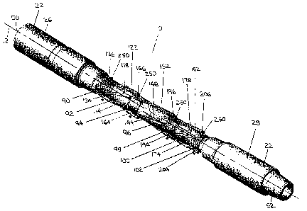
Referring to Figure 1, a downhole vibration tool (10) has a longitudinal tool
axis
(12). The vibration tool (10) is comprised of a housing (22). In the first
exemplary
embodiment of Figures 1-2, the housing (22) is comprised of a main housing
(24), a proximal
sub (26), and a distal sub (28).
The proximal sub (26) is connected with the main housing (24) with a threaded
connection (30). In the first exemplary embodiment of Figures 1-2, the
threaded connection
(30) is comprised of a box connector (32) on the main housing (24) and a pin
connector (34) on
the proximal sub (26). An 0-ring (36) is positioned between the box connector
(32) and the
pin connector (34) to provide a seal between the main housing (24) and the
proximal sub (26).
The distal sub (28) is connected with the main housing (24) with a threaded
connection (40). In the first exemplary embodiment of Figures 1-2, the
threaded connection
(40) is comprised of a box connector (42) on the main housing (24) and a pin
connector (44) on
the distal sub (28). An O-ring (46) is positioned between the box connector
(42) and the pin
connector (44) to provide a seal between the main housing (24) and the distal
sub (28).
-29-
CA 02802917 2013-01-21
WO 2012/083413 PCT/CA2011/001092
The proximal sub (26) is comprised of a proximal threaded connector (50) for
connecting the vibration tool (10) with a pipe string (not shown). In the
first exemplary
embodiment of Figures 1-2, the proximal threaded connector (50) is a box
connector.
The distal sub (28) is comprised of a distal threaded connector (52) for
connecting the vibration tool (10) with a pipe string (not shown). In the
first exemplary
embodiment of Figures 1-2, the distal threaded connector (52) is a pin
connector.
The drill string (not shown) has a nominal inner diameter. The proximal sub
(26) has a nominal inner diameter (54). The distal sub (28) has a nominal
inner diameter (56).
The proximal sub (26) and the distal sub (28) are configured so that the
nominal inner diameter
(54) of the proximal sub (26) and the nominal inner diameter (56) of the
distal sub (28) are
substantially similar to the nominal inner diameter of the drill string (not
shown) with which
the vibration tool (10) will be connected.
The main housing (24) has an inner diameter (60). The inner diameter (60) of
the main housing (24) is larger than the nominal inner diameter (54) of the
proximal sub (26)
and the nominal inner diameter (56) of the distal sub (28). The proximal sub
(26) is comprised
of a proximal inner diameter transition (62) which provides a transition
between the nominal
inner diameter (54) of the proximal sub (26) and the inner diameter (60) of
the main housing
(24). The distal sub (28) is comprised of a distal inner diameter transition
(64) which provides
a transition between the nominal inner diameter (56) of the distal sub (28)
and the inner
diameter of the main housing (24).
The housing (22) has an inner housing surface (70). The housing (22) contains
an unbalanced turbine assembly (72). The unbalanced turbine assembly (72) is
comprised of a
sleeve (74) which has an outer sleeve surface (76) and an inner sleeve surface
(78). The inner
sleeve surface (78) defines a sleeve bore (80) extending through the housing
(22). The inner
housing surface (70) and the outer sleeve surface (76) define an annular bore
(82) extending
through the housing (22).
The unbalanced turbine assembly (72) further comprises at least one annular
turbine which is rotatably contained within the annular bore (82) and which is
unbalanced
relative to the longitudinal tool axis (12).
-30-
CA 02802917 2013-01-21
WO 2012/083413 PCT/CA2011/001092
In the first exemplary embodiment of Figures 1-2, the unbalanced turbine
assembly (72) is comprised of the sleeve (74), a first proximal support ring
(90), a first annular
turbine (92), a first intermediate support ring (94), a second annular turbine
(96), a second
intermediate support ring (98), a third annular turbine (100), and a third
distal support ring
(102).
The support rings (90, 94, 98, 102) and the annular turbines (92, 96, 100) are
configured and arranged in the annular bore (82) so that a fluid (not shown)
may pass through
the annular bore (82). Stated otherwise, the support rings (90, 94, 98, 102)
and the annular
turbines (92, 96, 100) do not entirely block the annular bore (82).
The first annular turbine (92) is comprised of an annular structure having an
outer surface (110) which is adjacent to the inner housing surface (70) and an
inner surface
(112) which is adjacent to the outer sleeve surface (76). The first annular
turbine (92) is
provided with sufficient clearance with respect to the inner housing surface
(70) and the outer
sleeve surface (76) to permit the first annular turbine (92) to rotate
relatively freely within the
annular bore (82).
In the first exemplary embodiment of Figures 1-2, a plurality of first turbine
vanes (114) is located on the outer surface (110) of the first annular turbine
(92). In the first
exemplary embodiment of Figures 1-2, the first turbine vanes (114) are
comprised of blades
which extend along substantially the entire first turbine length (116) of the
first annular turbine
(92). The first turbine vanes (114) are arranged at an angle relative to the
longitudinal tool axis
(12) so that the first annular turbine (92) has a first turbine vane angle
(118). The first turbine
vanes (114) are tapered adjacent to the first proximal support ring (90) in
order to reduce
turbulence and energy losses as a fluid (not shown) passes into the first
annular turbine (92).
The first annular turbine (92) is rotatable about a first turbine rotation
axis (120)
and is unbalanced relative to the longitudinal tool axis (12). In the first
exemplary embodiment
of Figures 1-2, the first turbine rotation axis (120) is substantially
coincident with the
longitudinal tool axis (12) and the first annular turbine (92) is unbalanced
by configuring the
mass of the first annular turbine (92) so that the center of mass is offset
from the first turbine
rotation axis (120).
-31 -
CA 02802917 2013-01-21
WO 2012/083413 PCT/CA2011/001092
In the first exemplary embodiment of Figures 1-2, the first annular turbine
(92)
is initially fabricated so that the center of mass is substantially coincident
with the first turbine
rotation axis (120) and is subsequently modified by adding and/or removing
mass
asymmetrically from the first annular turbine (92). As best depicted in Figure
2, holes (122)
are drilled in one of the first turbine vanes (114) so that the center of mass
of the first annular
turbine (92) is offset. These holes (122) may either be left as voids, or may
be filled with a
material which has a lesser or greater density than the material from which
the first annular
turbine (92) is fabricated in order to provide that the first annular turbine
(92) is unbalanced.
The first proximal support ring (90) is comprised of an annular structure
having
an outer surface (130) which is adjacent to the inner housing surface (70) and
an inner surface
(132) which is adjacent to the outer sleeve surface (76).
In the first exemplary embodiment of Figures 1-2, a plurality of first
diverter
vanes (134) is located on the outer surface (130) of the first proximal
support ring (90). In the
first exemplary embodiment of Figures 1-2, the first diverter vanes (134) are
comprised of
blades which extend along the length of the first proximal support ring (90).
The first diverter
vanes (134) are arranged to have a first diverter vane angle (136) relative to
the longitudinal
tool axis (12).
The first diverter vane angle (136) is in a direction relative to the
longitudinal
tool axis (12) which is opposite to the first turbine vane angle (118). This
configuration of the
first diverter vane angle (136) and the first turbine vane angle (118) enables
a fluid (not shown)
passing through the annular bore (82) to impact the first turbine vanes (1 14)
at a lower angle of
incidence than if the first diverter vane angle (136) were parallel to the
longitudinal tool axis
(12) or in the same direction as the first turbine vane angle (118) relative
to the longitudinal
tool axis (12), thus potentially increasing the rotational energy which is
imparted to the first
annular turbine (92) by the fluid (not shown). In the first exemplary
embodiment of Figures 1-
2, the first diverter vane angle (136) may be minimized in order to minimize
turbulence at the
interface between the first proximal support ring (90) and the first annular
turbine (92).
The second annular turbine (96) is comprised of an annular structure having an
outer surface (140) which is adjacent to the inner housing surface (70) and an
inner surface
(142) which is adjacent to the outer sleeve surface (76). The second annular
turbine (96) is
provided with sufficient clearance with respect to the inner housing surface
(70) and the outer
-32-
CA 02802917 2013-01-21
WO 2012/083413 PCT/CA2011/001092
sleeve surface (76) to permit the second annular turbine (96) to rotate
relatively freely within
the annular bore (82).
In the first exemplary embodiment of Figures 1-2, a plurality of second
turbine
vanes (144) is located on the outer surface (140) of the second annular
turbine (96). In the first
exemplary embodiment of Figures 1-2, the second turbine vanes (144) are
comprised of blades
which extend along substantially the entire second turbine length (146) of the
second annular
turbine (96). The second turbine vanes (144) are arranged at an angle relative
to the
longitudinal tool axis (12) so that the second annular turbine (96) has a
second turbine vane
angle (148). The second turbine vanes (144) are tapered adjacent to the first
intermediate
support ring (94) in order to reduce turbulence and energy losses as a fluid
(not shown) passes
into the second annular turbine (96).
The second annular turbine (96) is rotatable about a second turbine rotation
axis
(150) and is unbalanced relative to the longitudinal tool axis (12). In the
first exemplary
embodiment of Figures 1-2, the second turbine rotation axis (150) is
substantially coincident
with the longitudinal tool axis (12) and the second annular turbine (96) is
unbalanced by
configuring the mass of the second annular turbine (96) so that the center of
mass is offset from
the second turbine rotation axis (150).
In the first exemplary embodiment of Figures 1-2, the second annular turbine
(96) is initially fabricated so that the center of mass is substantially
coincident with the second
turbine rotation axis (150) and is subsequently modified by adding and/or
removing mass
asymmetrically from the second annular turbine (96). As best depicted in
Figure 2, holes (152)
are drilled in one of the second turbine vanes (144) so that the center of
mass of the second
annular turbine (96) is offset. These holes (152) may either be left as voids,
or may be filled
with a material which has a lesser or greater density than the material from
which the second
annular turbine (96) is fabricated in order to provide that the second annular
turbine (96) is
unbalanced.
The first intermediate support ring (94) is comprised of an annular structure
having an outer surface (160) which is adjacent to the inner housing surface
(70) and an inner
surface (162) which is adjacent to the outer sleeve surface (76),
- 33 -
CA 02802917 2013-01-21
WO 2012/083413 PCT/CA2011/001092
In the first exemplary embodiment of Figures 1-2, a plurality of second
diverter
vanes (164) is located on the outer surface (160) of the first intermediate
support ring (94). In
the first exemplary embodiment of Figures 1-2, the second diverter vanes (164)
are comprised
of blades which extend along the length of the first intermediate support ring
(94). The second
diverter vanes (164) are arranged to have a second diverter vane angle (166)
relative to the
longitudinal tool axis (12).
The second diverter vane angle (166) is in a direction relative to the
longitudinal
tool axis (12) which is opposite to the second turbine vane angle (148). This
configuration of
the second diverter vane angle (166) and the second turbine vane angle (148)
enables a fluid
(not shown) passing through the annular bore (82) to impact the second turbine
vanes (144) at
a lower angle of incidence than if the second diverter vane angle (166) were
parallel to the
longitudinal tool axis (12) or in the same direction as the second turbine
vane angle (148)
relative to the longitudinal tool axis (12), thus potentially increasing the
rotational energy
which is imparted to the second annular turbine (96) by the fluid (not shown).
In the first
exemplary embodiment of Figures 1-2, the second diverter vane angle (166) may
be minimized
in order to minimize turbulence at the interfaces between the first
intermediate support ring
(94) and the first annular turbine (92) and the second annular turbine (96).
The third annular turbine (100) is comprised of an annular structure having an
outer surface (170) which is adjacent to the inner housing surface (70) and an
inner surface
(172) which is adjacent to the outer sleeve surface (76). The third annular
turbine (100) is
provided with sufficient clearance with respect to the inner housing surface
(70) and the outer
sleeve surface (76) to permit the third annular turbine (100) to rotate
relatively freely within
the annular bore (82).
In the first exemplary embodiment of Figures 1-2, a plurality of third turbine
vanes (174) is located on the outer surface (170) of the third annular turbine
(100). In the first
exemplary embodiment of Figures 1-2, the third turbine vanes (174) are
comprised of blades
which extend along substantially the entire third turbine length (176) of the
third annular
turbine (100). The third turbine vanes (174) are arranged at an angle relative
to the
longitudinal tool axis (12) so that the third annular turbine (100) has a
third turbine vane angle
(178). The third turbine vanes (174) are tapered adjacent to the second
intermediate support
ring (98) in order to reduce turbulence and energy losses as a fluid (not
shown) passes into the
third annular turbine (100).
-34-
CA 02802917 2013-01-21
WO 2012/083413 PCT/CA2011/001092
The third annular turbine (100) is rotatable about a third turbine rotation
axis
(180) and is unbalanced relative to the longitudinal tool axis (12). In the
first exemplary
embodiment of Figures 1-2, the third turbine rotation axis (180) is
substantially coincident with
the longitudinal tool axis (12) and the third annular turbine (100) is
unbalanced by configuring
the mass of the third annular turbine (100) so that the center of mass is
offset from the third
turbine rotation axis (180).
In the first exemplary embodiment of Figures 1-2, the third annular turbine
(100) is initially fabricated so that the center of mass is substantially
coincident with the third
turbine rotation axis (180) and is subsequently modified by adding and/or
removing mass
asymmetrically from the third annular turbine (100). As best depicted in
Figure 2, holes (182)
are drilled in one of the third turbine vanes (174) so that the center of mass
of the third annular
turbine (100) is offset. These holes (182) may either be left as voids, or may
be filled with a
material which has a lesser or greater density than the material from which
the third annular
turbine (100) is fabricated in order to provide that the third annular turbine
(100) is unbalanced.
The second intermediate support ring (98) is comprised of an annular structure
having an outer surface (190) which is adjacent to the inner housing surface
(70) and an inner
surface (192) which is adjacent to the outer sleeve surface (76).
In the first exemplary embodiment of Figures 1-2, a plurality of third
diverter
vanes (194) is located on the outer surface (190) of the second intermediate
support ring (98).
In the first exemplary embodiment of Figures 1-2, the third diverter vanes
(194) are comprised
of blades which extend along the length of the second intermediate support
ring (98). The third
diverter vanes (194) are arranged to have a third diverter vane angle (196)
relative to the
longitudinal tool axis (12).
The third diverter vane angle (196) is in a direction relative to the
longitudinal
tool axis (12) which is opposite to the third turbine vane angle (178). This
configuration of the
third diverter vane angle (196) and the third turbine vane angle (178) enables
a fluid (not
shown) passing through the annular bore (82) to impact the third turbine vanes
(174) at a lower
angle of incidence than if the third diverter vane angle (196) were parallel
to the longitudinal
tool axis (12) or in the same direction as the third turbine vane angle (178)
relative to the
longitudinal tool axis (12), thus potentially increasing the rotational energy
which is imparted
- 35 -
CA 02802917 2013-01-21
WO 2012/083413 PCT/CA2011/001092
to the third annular turbine (100) by the fluid (not shown). In the first
exemplary embodiment
of Figures 1-2, the third diverter vane angle (196) may be minimized in order
to minimize
turbulence at the interfaces between the second intermediate support ring (98)
and the second
annular turbine (96) and the third annular turbine (100).
The third distal support ring (102) is comprised of an annular structure
having
an outer surface (200) which is adjacent to the inner housing surface (70) and
an inner surface
(202) which is adjacent to the outer sleeve surface (76).
In the first exemplary embodiment of Figures 1-2, a plurality of distal
diverter
vanes (204) is located on the outer surface (200) of the third distal support
ring (102). In the
first exemplary embodiment of Figures 1-2, the distal diverter vanes (204) are
comprised of
blades which extend along the length of the third distal support ring (102).
The distal diverter
vanes (204) are arranged to be substantially parallel with the longitudinal
tool axis (12) in
order to direct a fluid (not shown) passing through the annular bore (82) in a
direction which is
substantially parallel with the longitudinal tool axis (12), so that a distal
diverter vane angle
(206) is substantially zero.
In the first exemplary embodiment of Figures 1-2, the first intermediate
support
ring (94) provides a combined first distal support ring and second proximal
support ring, and
the second intermediate support ring (98) provides a combined second distal
support ring and
third proximal support ring.
In the first exemplary embodiment of Figures 1-2, a proximal first turbine
bearing (210) is located between the first proximal support ring (90) and a
proximal first
turbine end (212) of the first annular turbine (92), a distal first turbine
bearing (214) is located
between a distal first turbine end (216) of the first annular turbine (92) and
the first
intermediate support ring (94), a proximal second turbine bearing (218) is
located between the
first intermediate support ring (94) and a proximal second turbine end (220)
of the second
annular turbine (96), a distal second turbine bearing (222) is located between
a distal second
turbine end (224) of the second annular turbine (96) and the second
intermediate support ring
(98), a proximal third turbine bearing (226) is located between the second
intermediate support
ring (98) and a proximal third turbine end (228) of the third annular turbine
(100), and a distal
third turbine bearing (230) is located between a distal third turbine end
(232) of the third
annular turbine (100) and the third distal support ring (102).
-36-
CA 02802917 2013-01-21
WO 2012/083413 PCT/CA2011/001092
Referring to Figures 1-2, the sleeve (74) has a proximal sleeve end (240) and
a
distal sleeve end (242).
In the first exemplary embodiment of Figures 1-2, an inlet (244) is defined by
the proximal sleeve end (240), the first proximal support ring (90) and the
proximal inner
diameter transition (62), so that a fluid (not shown) passing through the
proximal sub (26) can
be introduced into the sleeve bore (80) and the annular bore (82). As depicted
in Figures 1-2,
the proximal sleeve end (240) and the first proximal support ring (90) are
tapered adjacent to
the inlet (244) in order to reduce turbulence and energy losses at the inlet
(244).
In some embodiments, a flow control device (not shown in Figures 1-2) may be
associated with the inlet (244) so that a fluid (not shown) may be selectively
directed through
the sleeve bore (80) and/or the annular bore (82).
In the first exemplary embodiment of Figures 1-2, an outlet (246) is defined
by
the distal sleeve end (242), the third distal support ring (102) and the
distal inner diameter
transition (64), so that a fluid (not shown) passing through the sleeve bore
(80) and the annular
bore (82) can be discharged into the distal sub (28).
As previously indicated, in the first exemplary embodiment of Figures 1-2, the
unbalanced turbine assembly (72) is comprised of the sleeve (74), the first
proximal support
ring (90), the first annular turbine (92), the first intermediate support ring
(94), the second
annular turbine (96), the second intermediate support ring (98), the third
annular turbine (100),
and the third distal support ring (102).
In the first exemplary embodiment of Figures 1-2, the unbalanced turbine
assembly (72) is configured so that it may be inserted into the main housing
(24) and removed
from the main housing (24) fully assembled.
In the first exemplary embodiment of Figures 1-2, the sleeve (74) is connected
with the first proximal support ring (90) by an interference fit between the
inner surface (132)
of the first proximal support ring (90) and the outer sleeve surface (76).
Optionally, the sleeve
may also be connected by interference fits between the outer sleeve surface
(76) and the first
-37-
CA 02802917 2013-01-21
WO 2012/083413 PCT/CA2011/001092
intermediate support ring (94), the second intermediate support ring (98)
and/or the third distal
support ring (102).
Alternatively, the sleeve (74) may be fixedly connected with one or more of
the
first proximal support ring (90), the first intermediate support ring (94),
the second
intermediate support ring (98) and/or the third distal support ring (102). The
sleeve (74) may
be fixedly connected with one or more of the support rings (90, 94, 98, 102)
in any suitable
manner.
The unbalanced turbine assembly (72) may be connected with the housing (22)
by connecting the first proximal support ring (90), the first intermediate
support ring (94), the
second intermediate support ring (98) and/or the third distal support ring
(102) with the main
housing (24). For example, the unbalanced turbine assembly (72) may be fixedly
connected
with one or more of the support rings (90, 94, 98, 102) in any suitable
manner.
In the first exemplary embodiment of Figures 1-2, each of the first proximal
support ring (90), the first intermediate support ring (94), the second
intermediate support ring
(98) and the third distal support ring (102) are fixedly connected with the
main housing (24)
with one or more dowels (250) which extend through dowel bores (252) in the
main housing
(24) and into corresponding dowel bores (254) in the support rings (90, 94,
98, 102).
Following installation of the dowels (250), pipe plugs (256) may be inserted
into the dowel
bores (252) to seal the dowel bores (252).
In the first exemplary embodiment of Figures 1-2, the proximal sleeve end
(240)
is comprised of a projection (260) for engaging with the first proximal
support ring (90) in
order to limit the movement of the sleeve (74) relative to the first proximal
support ring (90).
In the first exemplary embodiment of Figures 1-2, the projection (260) is
comprised of a
radially extending lip or rim at the proximal sleeve end (240).
As a result, in the first exemplary embodiment of Figures 1-2, the unbalanced
turbine assembly (72) may be assembled by sliding the annular turbines (92,
96, 100) and the
support rings (90, 94, 98, 102) onto the sleeve (74) from the distal sleeve
end (242) in
sequence, beginning with the first proximal support ring (90).
-38-
CA 02802917 2013-01-21
WO 2012/083413 PCT/CA2011/001092
In order to complete the assembly of the vibration tool (10), the unbalanced
turbine assembly (72) may be inserted into the main housing (24) from either
end and may be
secured to the main housing (24) with the dowels (250) and pipe plugs (256).
One of the
proximal sub (26) and the distal sub (28) may be threaded onto the main
housing (24) before
the unbalanced turbine assembly (72) is inserted into the main housing (24),
but the other of
the subs (26, 28) is threaded onto the main housing (24) after the unbalanced
turbine assembly
(72) is inserted into the main housing (24).
In order to disassemble the vibration tool (10), one of the proximal sub (26)
and
the distal sub (28) may be unthreaded from the main housing (24), the pipe
plugs (256) and
dowels (250) may be removed from the main housing (24), and the unbalanced
turbine
assembly (72) may be removed from the main housing (24). In the event that the
unbalanced
turbine assembly (72) becomes stuck in the main housing (24), the sleeve (74)
may be removed
from the main housing (24) separately from the other components of the
unbalanced turbine
assembly (72) by pulling on the proximal sleeve end (240) after unthreading
the proximal sub
(26) from the main housing (24).
The ease of assembly and disassembly of the vibration tool (10) facilitates
servicing the vibration tool (10) and/or replacing or substituting parts of
the vibration tool (10).
The configuration of the unbalanced turbine assembly (72) supports the ease of
assembly and disassembly of the vibration tool (10), enables the annular
turbines (92, 96, 100)
to be supported within the main housing (24) by the main housing (24), the
sleeve (74) and the
support rings (90, 94, 98, 102), and may assist in transmitting vibration
produced by the
annular turbines (92, 96, 100) to the main housing (24).
The sleeve (74) as a component of the unbalanced turbine assembly (72)
provides several purposes. First, the sleeve (74) facilitates the assembly and
disassembly of
the vibration tool (10) by providing a structure upon which to assemble the
components of the
unbalanced turbine assembly (72). Second, the sleeve (74) serves as a barrier
between the
sleeve bore (80) and the inner surfaces (112, 142, 172) of the annular
turbines (92, 96, 100) and
thus prevents fluid (not shown) passing through the sleeve bore (80) from
interfering with the
rotation of the annular turbines (92, 96, 100). Third, the sleeve (74) may
assist in protecting
the turbine bearings (210, 214, 218, 222, 226, 230) by reducing fluid flow
through the bearings
(210, 214, 218, 222, 226, 230) from the inner surfaces (112, 142, 172) of the
annular turbines
-39-
CA 02802917 2013-01-21
WO 2012/083413 PCT/CA2011/001092
and/or the inner surfaces (132, 162, 192, 202) of the support rings (90, 94,
98, 102). Fourth,
the tapered proximal sleeve end (240) may assist in directing fluid (not
shown) into the annular
bore (82) at the inlet (244).
The sleeve (74) has a sleeve bore diameter (262). In the first exemplary
embodiment of Figures 1-2, the sleeve bore diameter (262) is maximized in
order to enable
fluid (not shown) and tools (not shown) to pass through the sleeve bore (80)
and the vibration
tool (10) without significant restriction.
In the first exemplary embodiment of Figures 1-2, the sleeve bore diameter
(262) may be configured to be substantially identical to or within a desired
ratio to the nominal
inner diameter (54) of the proximal sub (26) and/or the nominal inner diameter
(56) of the
distal sub (28).
This configuration may be achieved by providing the main housing (24) with a
larger outer dimension than the proximal sub (26) and/or the distal sub (28),
and/or by
providing the main housing (24) with an increased inner diameter (60) in order
to
accommodate the unbalanced turbine assembly (72) therein.
In achieving this configuration, a balance must be sought between providing an
acceptable sleeve bore diameter (262) and providing a suitable ratio between
the cross-
sectional area of the sleeve bore (80) and the cross-sectional area of the
annular bore (82),
since a suitable amount of fluid (not shown) must pass through the annular
bore (82) in order to
drive the annular turbines (92, 96, 100).
In the first exemplary embodiment of Figures 1-2, a goal in configuring the
vibration tool (10) is to provide that at least about 25 percent of the fluid
(not shown) which
passes through the vibration tool (10) passes through the annular bore (82),
so that no greater
than about 75 percent of the fluid (not shown) which passes through the
vibration tool (10)
passes through the sleeve bore (80). As a result, in the first exemplary
embodiment of Figures
1-2, the main housing (24), the sleeve (74), the annular turbines (92, 96,
100) and the support
rings (90, 94, 98, 102) are configured to provide that an adequate amount of
the fluid (not
shown) passes through the annular bore (82).
-40-
CA 02802917 2013-01-21
WO 2012/083413 PCT/CA2011/001092
In the first exemplary embodiment of Figures 1-2, the vibration tool (10) is
comprised of three annular turbines (92, 96, 100). In other embodiments, the
vibration tool
(10) may be comprised of one annular turbine, two annular turbines, or more
than three annular
turbines. Each of the annular turbines which may be included in the vibration
tool (10) may be
configured to provide a desired vibration frequency and a desired vibration
amplitude when
supplied with a design fluid energy.
The vibration frequency which is provided by an annular turbine is dependent
at
least in part upon the turbine rotation rate of the annular turbine. The
vibration amplitude
which is provided by an annular turbine is dependent at least in part upon the
turbine torque
which is generated by the annular turbine during rotation. The vibration
frequency and the
vibration amplitude of an annular turbine is dependent at least in part upon
the fluid energy
which is provided to the annular turbine.
The desired vibration frequencies of the annular turbines may be the same or
may be different from each other. The desired vibration frequencies of the
annular turbines
may be selected to cancel unwanted vibration frequencies in the pipe string
(not shown) and/or
to impart one or more vibration frequencies to the pipe string (not shown) to
reduce the
likelihood of the pipe string (not shown) becoming stuck in a borehole (not
shown).
In the first exemplary embodiment of Figures 1-2, the first annular turbine
(92)
is configured to rotate at a first turbine rotation rate at a design fluid
energy in order to provide
a desired vibration frequency, the second annular turbine (96) is configured
to rotate at a
second turbine rotation rate at the desired fluid energy in order to provide a
desired vibration
frequency, and the third annular turbine (100) is configured to rotate at a
third turbine rotation
rate at the desired fluid energy in order to provide a desired vibration
frequency.
In the first exemplary embodiment of Figures 1-2, the first turbine rotation
rate,
the second turbine rotation rate and the third turbine rotation rate are
preferably different from
each other. For example, it is believed that a vibration frequency of about
19.2 Hz (about 1150
rpm) which is imparted to a pipe string (not shown) may not significantly
interfere with
telemetry systems which may be used with the pipe string (not shown), but
vibration
frequencies above and below about 19.2 Hz (about 1150 rpm) may significantly
interfere with
telemetry systems and may thus be considered to be unwanted vibration
frequencies.
-41 -
CA 02802917 2013-01-21
WO 2012/083413 PCT/CA2011/001092
As a result, in the first exemplary embodiment of Figures 1-2, one of the
annular
turbines (92, 96, 100) may be configured to rotate at a turbine rotation rate
which will produce
a desired vibration frequency in the pipe string (not shown) which is greater
than 19.2 Hz
(about 1150 rpm), one of the annular turbines (92, 96, 100) may be configured
to rotate at a
turbine rotation rate which will produce a desired vibration frequency in the
pipe string (not
shown) which is less than 19.2 Hz (about 1150 rpm), and one of the annular
turbines (92, 96,
100) may be configured to rotate at a turbine rotation rate which will produce
a desired
vibration frequency in the pipe string (not shown) which is about equal to
about 19.2 Hz (about
1150 rpm).
More particularly, in the first exemplary embodiment of Figures 1-2, the first
annular turbine (92) may be configured to rotate at a first turbine rotation
rate which will
produce a desired vibration frequency in the pipe string (not shown) which is
greater than 19.2
Ilz (about 1150 rpm), the third annular turbine (100) may be configured to
rotate at a third
turbine rotation rate which will produce a desired vibration frequency in the
pipe string (not
shown) which is less than 19.2 Hz (about 1150 rpm), and the second annular
turbine (96) may
be configured to rotate at a second turbine rotation rate which will produce a
desired vibration
frequency in the pipe string (not shown) which is about equal to about 19.2 Hz
(about 1 150
rpm).
The turbine rotation rate is dependent at least in part upon both the turbine
vane
angle and the associated diverter vane angle. For example, the first turbine
rotation rate is
dependent at least in part upon the first turbine vane angle (118) and the
first diverter vane
angle (136), the second turbine rotation rate is dependent at least in part
upon the second
turbine vane angle (148) and the second diverter vane angle (166), and the
third turbine
rotation rate is dependent at least in part upon the third turbine vane angle
(178) and the third
diverter vane angle (196).
In general, the lower the angle of incidence between the fluid (not shown) and
the turbine vanes when the fluid (not shown) impacts the turbine vanes (and
thus the greater
the combined turbine vane angle and diverter vane angle), the higher the
turbine rotation rate.
As a result, the turbine rotation rate of an annular turbine may generally be
increased by
increasing the turbine vane angle and/or the associated diverter vane angle,
and may generally
be decreased by decreasing the turbine vane angle and/or the associated
diverter vane angle.
-42-
CA 02802917 2013-01-21
WO 2012/083413 PCT/CA2011/001092
The turbine rotation rate of an annular turbine may also be dependent upon
other factors, including but not limited to the number of turbine vanes, the
length of the turbine
vanes, the height of the turbine vanes, and the shape of the turbine vanes,
the length of the
annular turbine, and the mass of the annular turbine.
In the first exemplary embodiment of Figures 1-2, the first annular turbine
(92)
is configured to generate a first turbine torque at a design fluid energy, the
second annular
turbine (96) is configured to generate a second turbine torque at the desired
fluid energy, and
the third annular turbine (100) is configured to generate a third turbine
torque at the desired
fluid energy.
In the first exemplary embodiment of Figures 1-2, the annular turbines (92,
96,
100) may be configured so that the first turbine torque, the second turbine
torque and the third
turbine torque are either similar to each other or different from each other.
The turbine torque which is generated by an annular turbine during rotation is
dependent at least in part upon the turbine length. An annular turbine having
a relatively
longer turbine length will generally generate more torque than an annular
turbine having a
relatively shorter turbine length because a longer annular turbine provides
greater opportunity
for fluid energy to be transferred to the annular turbine as the fluid (not
shown) passes around
and/or through the annular turbine.
For example, in the first exemplary embodiment of Figures 1-2, the second
turbine length (146) may be longer than the first turbine length (116) and/or
the third turbine
length (176) so that the second annular turbine (96) may be configured to
generate a second
turbine torque which is greater than the first turbine torque and/or the third
turbine torque.
This configuration may enable the vibration tool (10) to provide a higher
vibration energy for
vibrating the pipe string (not shown) than is provided for cancelling unwanted
vibrations in the
pipe string (not shown).
The turbine torque generated by an annular turbine may also be dependent upon
other factors, including but not limited to the number of turbine vanes, the
length of the turbine
vanes, the height of the turbine vanes, the shape of the turbine vanes, and
the mass of the
annular turbine. The vibration amplitude of an annular turbine may also be
dependent upon the
magnitude of the imbalance of the annular turbine.
-43-
CA 02802917 2013-01-21
WO 2012/083413 PCT/CA2011/001092
As indicated above, the desired vibration frequency and the desired vibration
amplitude of an annular turbine is dependent at least in part upon a design
fluid energy. The
design fluid energy may be expressed as the amount of fluid energy to which
the vibration tool
(10) is expected to be exposed during operation. The design fluid energy is
dependent upon
the fluid energy requirements and/or limits of the operation which is being
conducted in the
borehole (not shown) and/or of the components which are included in the pipe
string (not
shown).
For example, a drilling motor (not shown) may be designed to operate at a
maximum fluid flowrate through the drilling motor (not shown). This maximum
fluid flow rate
may provide an indication of the amount of fluid energy to which the vibration
tool (10) may
be exposed during operation. The actual fluid energy to which the vibration
tool (10) may be
exposed during operation may, in addition to the flowrate of the fluid, be
influenced by other
factors including the pressure, density and temperature of the fluid.
Using empirical data, charts or tables which correlate fluid flow rates (or
fluid
energy) with rotation rates and vane angles, a combination of turbine vane
angle and diverter
vane angle can be determined which will provide a desired turbine rotation
rate and thus
vibration frequency. This combination of turbine vane angle and diverter vane
angle should
take into account the relative amounts of fluid (not shown) which can be
expected to pass
through the sleeve bore (80) and the annular bore (82) during operation of the
vibration tool
(10).
In practice, it may be very difficult to attain or maintain a specific design
fluid
energy during the operation of the vibration tool (10). As a result, the
vibration tool (10) may
be configured to operate within a range of vibration frequencies which may
conceivably be
controlled by the operator of the pipe string during operation of the
vibration tool (10) by
adjusting the fluid flow rate through the vibration tool (10) within a range
of fluid flow rates,
or by otherwise controlling the components of the pipe string (not shown).
An exemplary configuration for the vibration tool (10) in the first exemplary
embodiment of Figures 1-2 is as follows.
-44-
CA 02802917 2013-01-21
WO 2012/083413 PCT/CA2011/001092
The nominal outer diameter of the vibration tool (10) may be 4.875 inches
(about 12.4 centimeters). The nominal inner diameter of the pipe string (not
shown) may be
2.25 inches (about 5.7 centimeters). In the exemplary configuration, the
vibration tool (10)
may be configured to be used in a pipe string (not shown) which includes a
positive
displacement drilling motor having a nominal outer diameter of 4.75 inches
(about 12.1
centimeters) and which is designed for a maximum fluid flow rate of about 275
U.S. gallons
per minute (about 1040 liters per minute).
The nominal inner diameter (54) of the proximal sub (26) may be about 3.0
inches (about 7.6 centimeters). The nominal inner diameter (56) of the distal
sub (28) may be
about 2.25 inches (about 5.7 centimeters). The inner diameter (60) of the main
housing (24)
may be about 3.8 inches (about 9.7 centimeters). The sleeve bore diameter
(262) may be about
2.25 inches (about 5.7 centimeters). The diameter of the outer sleeve surface
(76) may be
about 2.50 inches (about 6.4 centimeters).
The vibration tool (10) may have an overall length of about 60 inches (about
150 centimeters). The length of the first proximal support ring (90) may be
about 3.5 inches
(about 8.9 centimeters). The first turbine length (116) may be about 4 inches
(about 10.2
centimeters). The length of the first intermediate support ring (94) may be
about 2.5 inches
(about 6.4 centimeters). The second turbine length (146) may be about 6 inches
(about 15.2
centimeters). The length of the second intermediate support ring (98) may be
about 2.5 inches
(about 6.4 centimeters). The third turbine length (176) may be about 4 inches
(about 10.2
centimeters). The length of the third distal support ring (102) may be about 1
inch (about 2.5
centimeters).
The first proximal support ring (90) may be comprised of three first diverter
vanes (134). The first annular turbine (92) may be comprised of four first
turbine vanes (114).
The first intermediate support ring (94) may be comprised of three second
diverter vanes (164).
The second annular turbine (96) may be comprised of six second turbine vanes
(144). The
second intermediate support ring (98) may be comprised of three third diverter
vanes (194).
The third annular turbine (100) may be comprised of eight third turbine vanes
(174). The third
distal support ring (102) may be comprised of three distal diverter vanes
(204).
The first diverter vane angle (136) may be less than about 5 degrees or about
l
degree. The first turbine vane angle (118) may be about 44 degrees. The second
diverter vane
-45-
CA 02802917 2013-01-21
WO 2012/083413 PCT/CA2011/001092
angle (166) may be about less than about 5 degrees or about 1 degree. The
second turbine vane
angle (148) may be about 48 degrees. The third diver-ter vane angle (196) may
be less than
about 5 degrees or about 1 degree. The third turbine vane angle (178) may be
about 52
degrees. The distal diverter vane angle (206) may be less than about 5 degrees
or about 1
degree.
In this exemplary configuration for the vibration tool (10), the annular
turbines
(92, 96, 100) are configured so that a progressively higher restriction to
fluid flow is provided
from the first annular turbine (92) to the second annular turbine (96) and
from the second
annular turbine (96) to the third annular turbine (100). This configuration is
achieved by
adjusting the number of turbine vanes (114, 144, 174), the turbine vane angles
(118, 148, 178),
and the turbine lengths (116, 146, 176) amongst the annular turbines (92, 96,
100).
In this exemplary configuration for the vibration tool (10), the diverter vane
angles (136, 166, 196, 206) are minimized in order to minimize turbulence at
the interfaces
between the support rings (90, 94, 98, 102) and the annular turbines (92, 96,
100).
An exemplary procedure for using the vibration tool (10) in the first
exemplary
embodiment of Figures 1-2 is as follows.
First, the vibration tool (10) is assembled. The vibration tool (10) is
assembled
by assembling the unbalanced turbine assembly (72), inserting the unbalanced
turbine
assembly (72) into the main housing (24), and securing the unbalanced turbine
assembly (72)
to the main housing (24) with the dowels (250) and pipe plugs (256). One of
the proximal sub
(26) and the distal sub (28) may be threaded onto the main housing (24) before
the unbalanced
turbine assembly (72) is inserted into the main housing (24), or both of the
subs (26, 28) may
be threaded onto the main housing (24) after the unbalanced turbine assembly
(72) is inserted
into the main housing (24).
The unbalanced turbine assembly (72) is assembled by sliding the annular
turbines (92, 96, 100) and the support rings (90, 94, 98, 102) onto the sleeve
(74) from the
distal sleeve end (242) in sequence, beginning with the first proximal support
ring (90).
In assembling the unbalanced turbine assembly (72), the annular turbines (92,
96, 100) and the support rings (90, 94, 98, 102) may be configured to provide
desired vibration
-46-
CA 02802917 2013-01-21
WO 2012/083413 PCT/CA2011/001092
frequencies of the annular turbines (92, 96, 100) by selecting annular
turbines (92, 96, 100)
with appropriate turbine vane angles (1 18, 148, 178) and by selecting support
rings (90, 94, 98)
with appropriate diverter vane angles (136, 166, 196).
In assembling the unbalanced turbine assembly (72), the annular turbines (92,
96, 100) may also be configured to provide desired vibration amplitudes of the
annular turbines
(92, 96, 100) by selecting annular turbines (92, 96, 100) having appropriate
turbine lengths
(116, 146, 176) and appropriate magnitudes of imbalance. If necessary, spacers
(not shown)
may be included in the unbalanced turbine assembly (72) to accommodate the
selected turbine
lengths (116, 146, 176) in order to ensure that the dowels (250) line up with
the dowel bores
(252) in the main housing (24) and the dowel bores (254) in the support rings
(90, 94, 98, 102).
Alternatively or additionally, support rings (90, 94, 98, 102) having varying
lengths may be
provided to accommodate the selected turbine lengths (116, 146, 176) in order
to ensure that
the dowels (250) line up with the dowel bores (252) in the main housing (24)
and the dowel
bores (254) in the support rings (90, 94, 98, 102). Alternatively or
additionally, the main
housing (24) may be provided with extra dowel bores (252) and corresponding
pipe plugs
(256) to accommodate different turbine lengths (116, 146, 176) which may be
selected.
Second, the vibration tool (10) is incorporated into a pipe string (not shown)
using the proximal threaded connector (50) on the proximal sub (26) and the
distal threaded
connector (52) on the distal sub (28).
Third, the pipe string (not shown) is lowered into a borehole (not shown).
Fourth, a fluid (not shown) is circulated through the pipe string (not shown)
so
that the fluid (not shown) passes through the vibration tool (10). The fluid
(not shown) passes
through the proximal sub (26) to the inlet (244).
If the vibration tool (10) does not include a flow control device (not shown
in
Figures 1-2), the fluid (not shown) is introduced into both the sleeve bore
(80) and the annular
bore (82) at the inlet (244). If the vibration tool (10) does include a flow
control device (not
shown in Figures 1-2), the fluid (not shown) is selectively introduced into
the sleeve bore (80)
and/or the annular bore (82), depending upon the actuation state of the flow
control device (not
shown in Figures 1-2).
-47-
CA 02802917 2013-01-21
WO 2012/083413 PCT/CA2011/001092
Fifth, the fluid (not shown) which is introduced into the annular bore (82)
passes through the annular bore (82), impacts upon the turbine vanes (114,
144, 174), and
causes the annular turbines (92, 96, 100) to rotate. The imbalance of the
annular turbines (92,
96, 100) causes the vibration tool (10) to vibrate as the annular turbines
(92, 96, 100) rotate.
The vibration of the vibration tool (10) is transmitted to the pipe string
(not shown) via the
subs (26, 28).
The vibration tool (10) may be configured to provide continuous vibration by
continuously permitting some amount of fluid (not shown) to flow through the
annular bore
(82). Alternatively, if the vibration tool (10) is provided with a flow
control device (not shown
in Figures 1-2), the flow control device (not shown in Figures 1-2) may
facilitate some control
over the flow of fluid (not shown) through the sleeve bore (80) and the
annular bore (82) in
order to control the vibration of the vibration tool (10).
The vibration frequencies and the vibration amplitudes of the annular turbines
(92, 96, 100) will be dependent upon many factors, including the selected
configuration of the
annular turbines (92, 96, 100) and the support rings (90, 94, 98, 102), the
fluid energy which is
provided to the vibration tool (10), and the actuation state of any flow
control device (not
shown in Figures 1-2) which is included in the vibration tool (10). The
vibrations provided by
the vibration tool (10) to the pipe string (not shown) may serve to reduce the
likelihood of the
pipe string (not shown) becoming stuck in the borehole (not shown), cause the
pipe string (not
shown) to become unstuck, and/or cancel unwanted vibrations in the pipe string
(not shown).
If more than one vibration tool (10) is incorporated into the pipe string (not
shown), the vibration tools (10) may be spaced along the pipe string (not
shown) to allow for
vibration of extended lengths of the pipe string (not shown), and/or may be
positioned within
the pipe string (not shown) in close proximity to sections of the pipe string
(not shown) which
may be particularly vulnerable to becoming stuck or which may be particularly
prone to
experiencing unwanted vibrations.
The second exemplary embodiment of the downhole vibration tool is now
described with reference to Figures 3-6.
In the description of the second exemplary embodiment, parts, components and
features of the second exemplary embodiment which are generally equivalent to
parts,
-48-
CA 02802917 2013-01-21
WO 2012/083413 PCT/CA2O11/001092
components and features of the first exemplary embodiment are assigned the
same reference
numbers as in the above description of the first exemplary embodiment.
In addition, the differences between the second exemplary embodiment and the
first exemplary embodiment consist essentially of differences in the
unbalanced turbine
assembly (72). As a result, the following description of the second exemplary
embodiment is
limited to a description of the unbalanced turbine assembly (72) of the second
exemplary
embodiment, and the description provided above with respect to the first
exemplary
embodiment is applicable to parts, components and features of the second
exemplary
embodiment other than the unbalanced turbine assembly (72) and to parts,
components and
features of the unbalanced turbine assembly (72) which are common to both the
first exemplary
embodiment and the second exemplary embodiment.
Referring to Figures 3-6, the unbalanced turbine assembly (72) of the second
exemplary embodiment is comprised of a sleeve (74), a first proximal support
ring (90), a first
annular turbine (92), a first intermediate support ring (94), a second annular
turbine (96), a
second intermediate support ring (98), a third annular turbine (100), and a
third distal support
ring (102), all of which are also included in the unbalanced turbine assembly
(72) of the first
exemplary embodiment.
The unbalanced turbine assembly (72) of the second exemplary embodiment
further comprises a retrievable plug (300), an auxiliary proximal support ring
(302), an
auxiliary annular turbine (304), and an unbalanced weight (306).
The auxiliary proximal support ring (302), the auxiliary annular turbine (304)
and the unbalanced weight (306) are configured and arranged in the annular
bore (82) so that a
fluid (not shown) may pass through the annular bore (82). Stated otherwise,
the auxiliary
proximal support ring (302), the auxiliary annular turbine (304) and the
unbalanced weight
(306) do not entirely block the annular bore (82).
The unbalanced turbine assembly (72) of the second exemplary embodiment
further comprises an auxiliary distal support ring which is combined with the
first proximal
support ring (90) so that the first proximal support ring (90) in the second
exemplary
embodiment is comprised of a combined auxiliary intermediate support ring
(308).
-49-
CA 02802917 2013-01-21
WO 2012/083413 PCT/CA2011/001092
The unbalanced turbine assembly (72) of the second exemplary embodiment
further comprises a proximal sleeve bearing (310) which is associated with the
auxiliary
proximal support ring (302), a distal sleeve bearing (312) which is associated
with the third
distal support ring (102), and an intermediate sleeve bearing (314) which is
associated with the
auxiliary intermediate support ring (308).
As depicted in Figure 3, the proximal sleeve bearing (310) is incorporated
into
the auxiliary proximal support ring (302), the distal sleeve bearing (312) is
incorporated into
the third distal support ring (102), and the intermediate sleeve bearing (314)
is incorporated
into the auxiliary intermediate support ring (308).
As depicted in Figures 3, the proximal sleeve bearing (310) is comprised of
four
races of rolling element bearings, the distal sleeve bearing (312) is
comprised of three races of
rolling element bearings, and the intermediate sleeve bearing (314) is
comprised of two races
of rolling element bearings. In other embodiments, the configuration of the
sleeve bearings
(310, 312, 314) may be different from the configuration depicted in Figure 3.
For example, in
some particular embodiments, the sleeve bearings (310, 312, 314) may each be
comprised of
four races of rolling element bearings.
As depicted in Figures 3-6, the unbalanced weight (306) is contained in the
annular bore (82) and is located axially between the third annular turbine
(100) and the third
distal support ring (102). As a result, as depicted in Figure 3, the distal
third turbine bearing
(230) from the first exemplary embodiment is omitted in the second exemplary
embodiment.
The unbalanced weight (306) is comprised of an annular structure having an
outer surface (320) which is adjacent to the inner housing surface (70) and an
inner surface
(322) which is adjacent to the outer sleeve surface (76). The unbalanced
weight (306) is
provided with sufficient clearance with respect to the inner housing surface
(70) to permit the
unbalanced weight (306) to rotate relatively freely within the annular bore
(82) relative to the
housing (22) and to permit a fluid (not shown) to pass through the annular
bore (82) between
the outer surface (320) of the unbalanced weight (306) and the inner housing
surface (70).
Depending upon the amount of clearance which is provided between the outer
surface (320) of
the unbalanced weight (306) and the inner housing surface (70), the unbalanced
weight (306)
may also define one or more passages therethrough for enabling a fluid (not
shown) to pass
through the unbalanced weight (306).
-50-
CA 02802917 2013-01-21
WO 2012/083413 PCT/CA2011/001092
In the second exemplary embodiment of Figures 3-6, the unbalanced weight
(306) is fixedly connected with the sleeve (74) by an interference fit between
the inner surface
(322) of the unbalanced weight (306) and the outer sleeve surface (76). More
particularly, in
the embodiment of the unbalanced weight (306) depicted in Figures 5-6, the
unbalanced weight
(306) is comprised of a split annular ring which is clamped to the outer
sleeve surface (76) with
a plurality of bolts (323).
The unbalanced weight (306) has an unbalanced weight rotation axis (324), an
unbalanced weight length (326), and is unbalanced relative to the longitudinal
tool axis (12).
In the second exemplary embodiment of Figures 3-6, the unbalanced weight
rotation axis (324)
is substantially coincident with the longitudinal tool axis (12) and the
unbalanced weight (306)
is unbalanced relative to the longitudinal tool axis (12) by configuring the
mass of the
unbalanced weight so that the center of mass is offset from the unbalanced
weight rotation axis
(324). In the embodiment of the unbalanced weight (306) depicted in Figures 5-
6, the
unbalanced weight (306) is initially fabricated so that the center of mass is
offset from the
unbalanced weight rotation axis (324).
In the second exemplary embodiment of Figures 3-6, the first annular turbine
(92), the second annular turbine (96), the third annular turbine (100) are all
fixedly connected
with the sleeve (74) so that rotation of the annular turbines (92, 96, 100)
results in rotation of
both the sleeve (74) and the unbalanced weight (306). As depicted in Figures 3-
4, the annular
turbines (92, 96, 100) are fixedly connected with the sleeve (74) with set
screws (not shown)
which extend between the inner surfaces (112, 142, 172) of the annular
turbines (92, 96, 100)
and the outer sleeve surface (76).
As a result, in the second exemplary embodiment, the sleeve (74) is rotatably
supported in the housing (22) by the sleeve bearings (310, 312, 314) and the
annular turbines
(92, 96, 100), the unbalanced weight (306) and the sleeve (74) are configured
to rotate together
as a unit within the housing (22).
In the second exemplary embodiment, the support rings (302, 308, 94, 98, 102)
are fixedly connected with the main housing (24) with one or more dowels (250)
which extend
through dowel bores (252) in the main housing (24) and into corresponding
dowel bores (254)
in the support rings (302, 308, 94, 98, 102), in a similar manner as in the
first exemplary
-51-
CA 02802917 2013-01-21
WO 2012/083413 PCT/CA2011/001092
embodiment, so that the annular turbines (92, 96, 100), the unbalanced weight
(306) and the
sleeve (74) rotate together as a unit within the housing, relative to both the
housing (22) and
the support rings (302, 308, 94, 98, 102).
In the second exemplary embodiment of Figures 3-6, the annular turbines (92,
96, 100) are substantially balanced (i.e., are not deliberately unbalanced).
In other
embodiments, the annular turbines (92, 96, 100) may be unbalanced in order to
enhance the
vibrations provided by the vibration tool (20).
In the second exemplary embodiment of Figures 3-6, the turbine lengths (116,
146, 176) of each of the annular turbines (92, 96, 100) are substantially the
same and the
turbine vane angles (118, 148, 178) of each of the annular turbines (92, 96,
100) are
substantially the same. In other embodiments, the turbine lengths (116, 146,
176) and the
turbine vane angles (118, 148, 178) of some or all of the annular turbines
(92, 96, 100) may be
different from each other, as long as the desired rotation characteristics of
the unbalanced
weight (306) can be achieved by the unbalanced turbine assembly (72).
The auxiliary annular turbine (304) is comprised of an annular structure
having
an outer surface (330) which is adjacent to the inner housing surface (70) and
an inner surface
(332) which is adjacent to the outer sleeve surface (76). The auxiliary
annular turbine (304) is
provided with sufficient clearance with respect to the inner housing surface
(70) and the outer
sleeve surface (76) to permit the auxiliary annular turbine (304) to rotate
relatively freely
within the annular bore (82). In addition, in the second exemplary embodiment
of Figures 3-6,
an auxiliary turbine sleeve bearing (333) is provided between the inner
surface (332) of the
auxiliary annular turbine (304) and the outer sleeve surface (76). As depicted
in Figure 3, the
auxiliary turbine sleeve bearing (333) is comprised of four races of rolling
element bearings.
In other embodiments, the configuration of the auxiliary turbine sleeve
bearing (333) may be
different from the configuration depicted in Figure 3.
As a result, in the second exemplary embodiment of Figures 3-6, the auxiliary
annular turbine (304) is not fixedly connected with the sleeve (74), but is
rotatably contained
within the annular bore (82) so that it is capable of rotating relative to
both the housing (22)
and the sleeve (74).
-52-
CA 02802917 2013-01-21
WO 2012/083413 PCT/CA2011/001092
In the second exemplary embodiment of Figures 3-6, a plurality of auxiliary
turbine vanes (334) is located on the outer surface (330) of the auxiliary
annular turbine (304).
In the second exemplary embodiment of Figures 3-6, the auxiliary turbine vanes
(334) are
comprised of blades which extend along substantially the entire auxiliary
turbine length (336)
of the auxiliary annular turbine (304). The auxiliary turbine vanes (334) are
arranged at an
angle relative to the longitudinal tool axis (12) so that the auxiliary
annular turbine (304) has
an auxiliary turbine vane angle (338). The auxiliary turbine vanes (334) may
be tapered
adjacent to the auxiliary proximal support ring (302) in order to reduce
turbulence and energy
losses as a fluid (not shown) passes into the auxiliary annular turbine (304).
The auxiliary annular turbine (304) is rotatable about an auxiliary turbine
rotation axis (340) and is unbalanced relative to the longitudinal tool axis
(12). In the second
exemplary embodiment of Figures 3-6, the auxiliary turbine rotation axis (340)
is substantially
coincident with the longitudinal tool axis (12) and the auxiliary annular
turbine (304) is
unbalanced by configuring the mass of the auxiliary annular turbine (304) so
that the center of
mass is offset from the auxiliary turbine rotation axis (340).
In the second exemplary embodiment of Figures 3-6, the auxiliary annular
turbine (304) is initially fabricated so that the center of mass is
substantially coincident with
the auxiliary turbine rotation axis (340) and is subsequently modified by
adding and/or
removing mass asymmetrically from the auxiliary annular turbine (304). For
example, in a
similar manner as the unbalanced annular turbines (92, 96, 100) of the first
exemplary
embodiment, holes (not shown) may be drilled in one of the auxiliary turbine
vanes (334) so
that the center of mass of the auxiliary unbalanced turbine (304) is offset.
These holes (not
shown) may either be left as voids, or may be filled with a material which has
a lesser or
greater density than the material from which the auxiliary unbalanced turbine
(304) is
fabricated in order to provide that the auxiliary unbalanced turbine (304) is
unbalanced.
In the second exemplary embodiment of Figures 3-6, a proximal auxiliary
turbine bearing (342) is located between the auxiliary proximal support ring
(302) and a
proximal auxiliary turbine end (344) of the auxiliary annular turbine (304)
and a distal
auxiliary turbine bearing (346) is located between a distal auxiliary turbine
end (348) of the
auxiliary annular turbine (304) and the auxiliary intermediate support ring
(308).
- 53 -
CA 02802917 2013-01-21
WO 2012/083413 PCT/CA2011/001092
In the second exemplary embodiment of Figures 3-6, the auxiliary turbine
length (336) of the auxiliary annular turbine (304) is greater than the
turbine lengths (116, 146,
176) of the annular turbines (92, 96, 100). In the exemplary embodiment of
Figures 3-6, the
auxiliary turbine vane angle (338) of the auxiliary annular turbine (304) is
in a direction
opposite to the turbine vane angles (118, 148, 178) of the annular turbines
(92, 96, 100)
relative to the longitudinal tool axis (12) so that the auxiliary annular
turbine (304) and the
annular turbines (92, 96, 100) are configured to rotate in opposite
directions.
In the second exemplary embodiment of Figures 3-6, the auxiliary proximal
support ring (302) is comprised of an annular structure having an outer
surface (350) which is
adjacent to the inner housing surface (70) and an inner surface (352) which is
adjacent to the
outer sleeve surface (76).
In the second exemplary embodiment of Figures 3-6, a plurality of auxiliary
diverter vanes (354) is located on the outer surface (350) of the auxiliary
proximal support ring
(302). In the second exemplary embodiment of Figures 3-6, the auxiliary
diverter vanes (354)
are comprised of blades which extend along the length of the auxiliary
proximal support ring
(302). The auxiliary diverter vanes (354) are arranged to have an auxiliary
diverter vane angle
(356) relative to the longitudinal tool axis (12).
The auxiliary diverter vane angle (356) is in a direction relative to the
longitudinal tool axis (12) which is opposite to the auxiliary turbine vane
angle (338). This
configuration of the auxiliary diverter vane angle (356) and the auxiliary
turbine vane angle
(338) enables a fluid (not shown) passing through the annular bore (82) to
impact the auxiliary
turbine vanes (334) at a lower angle of incidence than if the auxiliary
diverter vane angle (356)
were parallel to the longitudinal tool axis (12) or in the same direction as
the auxiliary turbine
vane angle (338) relative to the longitudinal tool axis (12), thus potentially
increasing the
rotational energy which is imparted to the auxiliary annular turbine (304) by
the fluid (not
shown).
In the second exemplary embodiment of Figures 3-6, the auxiliary diverter vane
angle (356) may be minimized in order to minimize turbulence at the interface
between the
auxiliary proximal support ring (302) and the auxiliary annular turbine (304).
Similarly, as
depicted in Figure 4, the first diverter vane angle (136) may be minimized in
order to minimize
-54-
CA 02802917 2013-01-21
WO 2012/083413 PCT/CA2011/001092
turbulence at the interface between the auxiliary intermediate support ring
(308) and the first
annular turbine (90).
In the second exemplary embodiment of Figures 3-6, the retrievable plug (300)
is associated with the inlet (244) as a flow control device so that a fluid
(not shown) may be
selectively directed through the annular bore (82) by blocking the sleeve bore
(80). As
depicted in Figures 3-4, the retrievable plug (300) is in the form of a
retrievable nose cone.
The retrievable plug (300) may be removably connected with the proximal sleeve
end (240)
with one or more shear pins (360) in order to block the sleeve bore (80). As
depicted in
Figures 3-4, the retrievable plug (300) is comprised of a fishing neck (362)
for facilitating
retrieval of the retrievable plug (300) with an appropriate retrieval tool in
order to un-block the
sleeve bore (80).
In summary, the unbalanced turbine assembly (72) of the second exemplary
embodiment provides separate vibrations from rotation of the unbalanced weight
(306) and
from rotation of the auxiliary annular turbine (304). In the second exemplary
embodiment,
rotation of the unbalanced weight (306) results from rotation of the annular
turbines (92, 96,
100). In the second exemplary embodiment, the annular turbines (92, 96, 100)
do not need to
be unbalanced, but the auxiliary annular turbine (304) is unbalanced. In the
second exemplary
embodiment, the unbalanced weight (306) and the auxiliary annular turbine
(304) may be
configured to rotate in opposite directions.
An exemplary configuration for the vibration tool (10) in the second exemplary
embodiment of Figures 3-6 is as follows.
The nominal outer diameter of the vibration tool (10) may be 5.25 inches
(about
13.3 centimeters). The nominal inner diameter of the pipe string (not shown)
may be 2.25
inches (about 5.7 centimeters). In the exemplary configuration, the vibration
tool (10) may be
configured to be used in a pipe string (not shown) which includes a positive
displacement
drilling motor having a nominal outer diameter of 4.75 inches (about 12.1
centimeters) and
which is designed for a maximum fluid flow rate of about 275 U.S. gallons per
minute (about
1040 liters per minute).
The nominal inner diameter (54) of the proximal sub (26) may be about 3.25
inches (about 8.3 centimeters). The nominal inner diameter (56) of the distal
sub (28) may be
- 55 -
CA 02802917 2013-01-21
WO 2012/083413 PCT/CA2011/001092
about 2.75 inches (about 7.0 centimeters). The inner diameter (60) of the main
housing (24)
may be about 3.83 inches (about 9.7 centimeters). The sleeve bore diameter
(262) may be
about 2.25 inches (about 5.7 centimeters). The diameter of the outer sleeve
surface (76) may
be about 2.50 inches (about 6.4 centimeters).
The vibration tool (10) may have an overall length of about 80 inches (about
203 centimeters). The length of the auxiliary proximal support ring (302) may
be about 3.75
inches (about 9.5 centimeters). The auxiliary turbine length (336) may be
about 6.5 inches
(about 16.5 centimeters). The length of the auxiliary intermediate support
ring (308) may be
about 3.75 inches (about 9.5 centimeters). The first turbine length (116) may
be about 2.5
inches (about 6.4 centimeters). The length of the first intermediate support
ring (94) may be
about 3.5 inches (about 8.9 centimeters). The second turbine length (146) may
be about 2.5
inches (about 6.4 centimeters). The length of the second intermediate support
ring (98) may be
about 3.5 inches (about 8.9 centimeters). The third turbine length (176) may
be about 2.5
inches (about 6.4 centimeters). The length of the unbalanced weight (306) may
be about 4.38
inches (about 11.1 centimeters). The length of the third distal support ring
(102) may be about
2.75 inches (about 7.0 centimeters).
The auxiliary proximal support ring (302) may be comprised of six auxiliary
diverter vanes (354). The auxiliary annular turbine (304) may be comprised of
ten auxiliary
turbine vanes (334). The auxiliary intermediate support ring (308) may be
comprised of three
first diverter vanes (134). The first annular turbine (92) may be comprised of
nine first turbine
vanes (114). The first intermediate support ring (94) may be comprised of six
second diverter
vanes (164). The second annular turbine (96) may be comprised of nine second
turbine vanes
(144). The second intermediate support ring (98) may be comprised of six third
diverter vanes
(194). The third annular turbine (100) may be comprised of nine third turbine
vanes (174).
The third distal support ring (102) may be comprised of three distal diverter
vanes (204).
The auxiliary diverter vane angle (356) may be about 48 degrees. The auxiliary
turbine vane angle (338) may be about 38 degrees. The first diverter vane
angle (136) may be
about 0 degrees. The first turbine vane angle (118) may be about 68 degrees.
The second
diverter vane angle (166) may be about 48 degrees. The second turbine vane
angle (148) may
be about 68 degrees. The third diverter vane angle (196) may be about 48
degrees. The third
turbine vane angle (178) may be about 68 degrees. The distal diverter vane
angle (206) may be
about 0 degrees.
-56-
CA 02802917 2013-01-21
WO 2012/083413 PCT/CA2011/001092
In this exemplary configuration for the vibration tool (10), the annular
turbines
(304, 92, 96, 100) may be configured so that a progressively higher
restriction to fluid flow is
provided from the auxiliary annular turbine (304) to the first annular turbine
(92), from the first
annular turbine (92) to the second annular turbine (96), and from the second
annular turbine
(96) to the third annular turbine (100). This configuration may be achieved by
adjusting the
number of turbine vanes (334, 114, 144, 174), the turbine vane angles (338,
118, 148, 178),
and the turbine lengths (336, 116, 146, 176) amongst the annular turbines
(304, 92, 96, 100).
In this exemplary configuration for the vibration tool (10), the diverter vane
angles (356, 136, 166, 196, 206) are minimized in order to minimize turbulence
at the
interfaces between the support rings (302, 308, 94, 98, 102) and the annular
turbines (304, 92,
96, 100).
An exemplary procedure for using the vibration tool (10) in the second
exemplary embodiment of Figures 3-6 is as follows.
First, the vibration tool (10) is assembled. The vibration tool (10) is
assembled
by assembling the unbalanced turbine assembly (72), inserting the unbalanced
turbine
assembly (72) into the main housing (24), and securing the unbalanced turbine
assembly (72)
to the main housing (24) with the dowels (250) and pipe plugs (256). One of
the proximal sub
(26) and the distal sub (28) may be threaded onto the main housing (24) before
the unbalanced
turbine assembly (72) is inserted into the main housing (24), or both of the
subs (26, 28) may
be threaded onto the main housing (24) after the unbalanced turbine assembly
(72) is inserted
into the main housing (24).
The unbalanced turbine assembly (72) is assembled by sliding the annular
turbines (304, 92, 96, 100), the support rings (302, 308, 94, 98, 102) and the
unbalanced weight
(306) onto the sleeve (74) from the distal sleeve end (242) in sequence,
beginning with the
auxiliary proximal support ring (304).
In assembling the unbalanced turbine assembly (72), the annular turbines (304,
92, 96, 100) and the support rings (302, 308, 94, 98, 102) may be configured
to provide desired
vibration frequencies of the unbalanced weight (306) and the auxiliary annular
turbine (304) by
selecting annular turbines (304, 92, 96, 100) with appropriate turbine vane
angles (338, 118,
-57-
CA 02802917 2013-01-21
WO 2012/083413 PCT/CA2011/001092
148, 178) and by selecting support rings (302, 308, 94, 98) with appropriate
diverter vane
angles (356, 136, 166, 196).
In assembling the unbalanced turbine assembly (72), the annular turbines (304,
92, 96, 100) may also be configured to provide desired vibration amplitudes of
the unbalanced
weight (306) and the auxiliary annular turbine (304) by selecting annular
turbines (304, 92, 96,
100) having appropriate turbine lengths (336, 116, 146, 176), by selecting an
unbalanced
weight having an appropriate unbalanced weight length (326), and by selecting
an unbalanced
weight (306) and an auxiliary annular turbine (304) having appropriate
magnitudes of
imbalance. If necessary, spacers (not shown) may be included in the unbalanced
turbine
assembly (72) to accommodate the selected turbine lengths (336, 116, 146, 176)
and the
selected unbalanced weight length (326) in order to ensure that the dowels
(250) line up with
the dowel bores (252) in the main housing (24) and the dowel bores (254) in
the support rings
(302, 308, 94, 98, 102). Alternatively or additionally, support rings (302,
308, 94, 98, 102)
having varying lengths may be provided to accommodate the selected turbine
lengths (336,
116, 146, 176) and the selected unbalanced weight length (326) in order to
ensure that the
dowels (250) line up with the dowel bores (252) in the main housing (24) and
the dowel bores
(254) in the support rings (302, 308, 94, 98, 102). Alternatively or
additionally, the main
housing (24) may be provided with extra dowel bores (252) and corresponding
pipe plugs
(256) to accommodate different turbine lengths (336, 116, 146, 176) and
different unbalanced
weight lengths (326) which may be selected.
Second, the vibration tool (10) is incorporated into a pipe string (not shown)
using the proximal threaded connector (50) on the proximal sub (26) and the
distal threaded
connector (52) on the distal sub (28).
Third, the pipe string (not shown) is lowered into a borehole (not shown).
Fourth, a fluid (not shown) is circulated through the pipe string (not shown)
so
that the fluid (not shown) passes through the vibration tool (10). The fluid
(not shown) passes
through the proximal sub (26) to the inlet (244).
If the vibration tool (10) does not include the retrievable plug (300) or some
other form of flow control device, the fluid (not shown) is introduced into
both the sleeve bore
(80) and the annular bore (82) at the inlet (244). If the vibration tool (10)
includes the
-58-
CA 02802917 2013-01-21
WO 2012/083413 PCT/CA2011/001092
retrievable plug (300) as a flow control device, the fluid (not shown) is
selectively introduced
only into the annular bore (82) because of the blocking of the sleeve bore
(80) by the
retrievable plug (300).
Fifth, the fluid (not shown) which is introduced into the annular bore (82)
passes through the annular bore (82), impacts upon the turbine vanes (334,
114, 144, 174), and
causes the unbalanced weight (306) and the auxiliary annular turbine (304) to
rotate. The
imbalance of the unbalanced weight (306) and the auxiliary annular turbine
(304) causes the
vibration tool (10) to vibrate as the annular turbines (304, 92, 96, 100)
rotate. The vibration of
the vibration tool (10) is transmitted to the pipe string (not shown) via the
subs (26, 28).
The retrievable plug (300) may be left connected with the proximal sleeve end
(240) as long as a relatively large amount of vibration is desired.
If, however, a smaller amount of vibration becomes desirable while the
vibration tool (10) is deployed in the borehole (not shown), a suitable
retrieval tool (not shown)
may be lowered into the pipe string (not shown), be engaged with the fishing
neck (362) on the
retrievable plug (300), and be withdrawn in order to shear the shear pins
(360) which connect
the retrievable plug (300) with the proximal sleeve end (240) and thereby
retrieve the
retrievable plug (300). Retrieval of the retrievable plug (300) will un-block
the sleeve bore
(80) and permit a portion of the fluid (not shown) which is circulating
through the vibration
tool (10) to be diverted from the annular bore (82) and into the sleeve bore
(80), thereby
reducing the amount of fluid energy which is provided to the annular turbines
(304, 92, 96,
100).
The vibration frequencies and the vibration amplitudes of the unbalanced
weight (306) and the auxiliary annular turbine (304) will be dependent upon
many factors,
including the selected configuration of the annular turbines (304, 92, 96,
100) and the support
rings (302, 308, 94, 98, 102), the fluid energy which is provided to the
vibration tool (10), and
the actuation state of the retrievable plug (300) or any other flow control
device which is
included in the vibration tool (10). The vibrations provided by the vibration
tool (10) to the
pipe string (not shown) may serve to reduce the likelihood of the pipe string
(not shown)
becoming stuck in the borehole (not shown), cause the pipe string (not shown)
to become
unstuck, and/or cancel unwanted vibrations in the pipe string (not shown).
-59-
CA 02802917 2013-01-21
WO 2012/083413 PCT/CA2011/001092
If more than one vibration tool (10) is incorporated into the pipe string (not
shown), the vibration tools (10) may be spaced along the pipe string (not
shown) to allow for
vibration of extended lengths of the pipe string (not shown), and/or may be
positioned within
the pipe string (not shown) in close proximity to sections of the pipe string
(not shown) which
may be particularly vulnerable to becoming stuck or which may be particularly
prone to
experiencing unwanted vibrations.
The third exemplary embodiment of the downhole vibration tool is now
described with reference to Figure 7.
In the description of the third exemplary embodiment, parts, components and
features of the third exemplary embodiment which are generally equivalent to
parts,
components and features of the first exemplary embodiment and/or the second
exemplary
embodiment are assigned the same reference numbers as in the above description
of the
previous exemplary embodiments.
In addition, the differences between the third exemplary embodiment and the
previous exemplary embodiments consist essentially of differences in the
unbalanced turbine
assembly (72). As a result, the following description of the third exemplary
embodiment is
limited to a description of the unbalanced turbine assembly (72) of the third
exemplary
embodiment, and the description provided above with respect to the first
exemplary
embodiment is applicable to parts, components and features of the third
exemplary
embodiment other than the unbalanced turbine assembly (72) and the description
provided
above with respect to the previous exemplary embodiments is applicable to
parts, components
and features of the unbalanced turbine assembly (72) which are common to both
the third
exemplary embodiment and the previous exemplary embodiments.
The third exemplary embodiment includes features of both the first exemplary
embodiment and the second exemplary embodiment.
Referring to Figure 7, the unbalanced turbine assembly (72) of the third
exemplary embodiment is comprised of a sleeve (74), a first proximal support
ring (90), a first
annular turbine (92), a first intermediate support ring (94), a second annular
turbine (96), a
second intermediate support ring (98), a third annular turbine (100), and a
third distal support
-60-
CA 02802917 2013-01-21
WO 2012/083413 PCT/CA2011/001092
ring (102), all of which are also included in the unbalanced turbine assembly
(72) of the first
exemplary embodiment.
The unbalanced turbine assembly (72) of the third exemplary embodiment
further comprises an unbalanced weight (306), which is also included in the
unbalanced turbine
assembly (72) of the second exemplary embodiment, and a lower support ring
(380), which is
not included in the unbalanced turbine assembly (72) of the previous exemplary
embodiments.
The unbalanced turbine assembly (72) of the third exemplary embodiment does
not include the auxiliary annular turbine (304) which is included in the
second exemplary
embodiment, or any of the features which are associated with the auxiliary
annular turbine
(304) in the second exemplary embodiment.
Furthermore, in the unbalanced turbine assembly (72) of the third exemplary
embodiment, the sleeve (74) is comprised of a solid rod. As a result, the
sleeve (74) in the
third exemplary embodiment does not include an inner sleeve surface which
defines a sleeve
bore as in the previous exemplary embodiments, and the unbalanced turbine
assembly (72) of
the third exemplary embodiment also does not include the retrievable plug
(300) which is
included in the second exemplary embodiment.
An advantage of providing a sleeve (74) without a sleeve bore is that all
fluid
(not shown) passing through the vibration tool (10) will pass through the
annular bore (82) and
will therefore be available to drive the annular turbines (92, 96, 100). A
disadvantage of
providing a sleeve (74) without a sleeve bore is that tools and other
equipment may not as
easily be passed through the vibration tool (10) in comparison with
embodiments in which the
sleeve (74) does include a sleeve bore.
The unbalanced weight (306) and the lower support ring (380) are configured
and arranged in the annular bore (82) so that a fluid (not shown) may pass
through the annular
bore (82). Stated otherwise, the unbalanced weight (306) and the lower support
ring (380) do
not entirely block the annular bore (82).
The unbalanced turbine assembly (72) of the third exemplary embodiment
further comprises a proximal sleeve bearing (not shown in Figure 7) which is
associated with
the first proximal support ring (90), a distal sleeve bearing (not shown in
Figure 7) which is
-61 -
CA 02802917 2013-01-21
WO 2012/083413 PCT/CA2011/001092
associated with the second intermediate support ring (98), and an intermediate
sleeve bearing
(not shown in Figure 7) which is associated with the first intermediate
support ring (94).
In the third exemplary embodiment of Figure 7, the proximal sleeve bearing is
incorporated into the first proximal support ring (90), the distal sleeve
bearing is incorporated
into the second intermediate support ring (98), and the intermediate sleeve
bearing is
incorporated into the first intermediate support ring (94).
In the third exemplary embodiment of Figure 7, the sleeve bearings are each
comprised of four races of rolling element bearings.
Referring to Figure 7, the unbalanced weight (306) is contained in the annular
bore (82) and is located axially between the third distal support ring (102)
and the lower
support ring (380). As a result, the distal third turbine bearing (not shown
in Figure 7) from
the first exemplary embodiment (which was omitted in the second exemplary
embodiment) is
included in the third exemplary embodiment.
In the third exemplary embodiment of Figure 7, the unbalanced weight (306) is
comprised of the structure depicted in Figures 5-6. More particularly, the
unbalanced weight is
an annular structure having an outer surface (320) which is adjacent to the
inner housing
surface (70) and an inner surface (322) which is adjacent to the outer sleeve
surface (76). The
unbalanced weight (306) is provided with sufficient clearance with respect to
the inner housing
surface (70) to permit the unbalanced weight (306) to rotate relatively freely
within the annular
bore (82) relative to the housing (22) and to permit a fluid (not shown) to
pass through the
annular bore (82) between the outer surface (320) of the unbalanced weight
(306) and the inner
housing surface (70). Depending upon the amount of clearance which is provided
between the
outer surface (320) of the unbalanced weight (306) and the inner housing
surface (70), the
unbalanced weight (306) may also define one or more passages therethrough for
enabling a
fluid (not shown) to pass through the unbalanced weight (306).
In the third exemplary embodiment of Figure 7, the unbalanced weight (306) is
fixedly connected with the sleeve (74) by an interference fit between the
inner surface (322) of
the unbalanced weight (306) and the outer sleeve surface (76). More
particularly, in the
embodiment of the unbalanced weight (306) depicted in Figures 5-6, the
unbalanced weight
-62-
CA 02802917 2013-01-21
WO 2012/083413 PCT/CA2011/001092
(306) is comprised of a split annular ring which is clamped to the outer
sleeve surface (76) with
a plurality of bolts (323).
The unbalanced weight (306) has an unbalanced weight rotation axis (324), an
unbalanced weight length (326), and is unbalanced relative to the longitudinal
tool axis (12).
In the third exemplary embodiment of Figure 7, the unbalanced weight rotation
axis (324) is
substantially coincident with the longitudinal tool axis (12) and the
unbalanced weight (306) is
unbalanced relative to the longitudinal tool axis (12) by configuring the mass
of the unbalanced
weight so that the center of mass is offset from the unbalanced weight
rotation axis (324). In
the embodiment of the unbalanced weight (306) depicted in Figures 5-6, the
unbalanced weight
(306) is initially fabricated so that the center of mass is offset from the
unbalanced weight
rotation axis (324).
In the third exemplary embodiment of Figure 7, the first annular turbine (92),
the second annular turbine (96), the third annular turbine (100) are all
fixedly connected with
the sleeve (74) so that rotation of the annular turbines (92, 96, 100) results
in rotation of both
the sleeve (74) and the unbalanced weight (306). As in the second exemplary
embodiment
depicted in Figures 3-4, the annular turbines (92, 96, 100) are fixedly
connected with the sleeve
(74) with set screws (not shown) which extend between the inner surfaces (not
shown in Figure
7) of the annular turbines (92, 96, 100) and the outer sleeve surface (76).
As a result, in the third exemplary embodiment as in the second exemplary
embodiment, the sleeve (74) is rotatably supported in the housing (22) by the
sleeve bearings
(310, 312, 314).and the annular turbines (92, 96, 100), the unbalanced weight
(306) and the
sleeve (74) are configured to rotate together as a unit within the housing
(22).
In the third exemplary embodiment, the support rings (90, 94, 98, 102, 380)
are
fixedly connected with the main housing (24) with one or more dowels (not
shown in Figure 7)
which extend through dowel bores (not shown in Figure 7) in the main housing
(24) and into
corresponding dowel bores (not shown in Figure 7) in the support rings (90,
94, 98, 102, 380),
in a similar manner as in the previous exemplary embodiments, so that the
annular turbines
(92, 96, 100), the unbalanced weight (306) and the sleeve (74) rotate together
as a unit within
the housing, relative to both the housing (22) and the support rings (90, 94,
98, 102, 380).
-63-
CA 02802917 2013-01-21
WO 2012/083413 PCT/CA2011/001092
In the third exemplary embodiment of Figure 7, the annular turbines (92, 96,
100) are substantially balanced (i.e., are not deliberately unbalanced). In
other embodiments,
the annular turbines (92, 96, 100) may be unbalanced in order to enhance the
vibrations
provided by the vibration tool (20).
In the third exemplary embodiment of Figure 7, the turbine lengths (116, 146,
176) of each of the annular turbines (92, 96, 100) are substantially the same
and the turbine
vane angles (118, 148, 178) of each of the annular turbines (92, 96, 100) are
substantially the
same. In other embodiments, the turbine lengths (116, 146, 176) and the
turbine vane angles
(118, 148, 178) of some or all of the annular turbines (92, 96, 100) may be
different from each
other, as long as the desired rotation characteristics of the unbalanced
weight (306) can be
achieved by the unbalanced turbine assembly (72).
In summary, in the third exemplary embodiment, rotation of the unbalanced
weight (306) results from rotation of the annular turbines (92, 96, 100). In
the third exemplary
embodiment, the annular turbines (92, 96, 100) do not need to be unbalanced.
An exemplary configuration for the vibration tool (10) in the third exemplary
embodiment of Figure 7 is as follows.
The nominal outer diameter of the vibration tool (10) may be 5.25 inches
(about
13.3 centimeters). The nominal inner diameter of the pipe string (not shown)
may be 2.25
inches (about 5.7 centimeters). In the exemplary configuration, the vibration
tool (10) may be
configured to be used in a pipe string (not shown) which includes a positive
displacement
drilling motor having a nominal outer diameter of 4.75 inches (about 12.1
centimeters) and
which is designed for a maximum fluid flow rate of about 275 U.S. gallons per
minute (about
1040 liters per minute).
The nominal inner diameter (54) of the proximal sub (26) may be about 3.25
inches (about 8.3 centimeters). The nominal inner diameter (56) of the distal
sub (28) may be
about 2.75 inches (about 7.0 centimeters). The inner diameter (60) of the main
housing (24)
may be about 3.93 inches (about 10 centimeters). The diameter of the outer
sleeve surface (76)
may be about 2.50 inches (about 6.4 centimeters).
-64-
CA 02802917 2013-01-21
WO 2012/083413 PCT/CA2011/001092
The vibration tool (10) may have an overall length of about 65 inches (about
165 centimeters). The length of the first proximal support ring (90) may be
about 2.25 inches
(about 5.7 centimeters). The first turbine length (92) may be about 2.0 inches
(about 5
centimeters). The length of the first intermediate support ring (94) may be
about 2.25 inches
(about 5.7 centimeters). The second turbine length (96) may be about 2.0
inches (about 5
centimeters). The length of the second intermediate support ring (98) may be
about 2.25
inches (about 5.7 centimeters). The third turbine length (100) may be about
2.0 inches (about 5
centimeters). The length of the third distal support ring (102) may be about
3.25 inches (about
8.3 centimeters). The length of the unbalanced weight (306) may be about 4.75
inches (about
12.1 centimeters). The length of the lower support ring (380) may be about
3.25 inches (about
8.3 centimeters).
The first proximal support ring (90) may be comprised of six first diverter
vanes
(134). The first annular turbine (92) may be comprised of ten first turbine
vanes (114). The
first intermediate support ring (308) may be comprised of six second diverter
vanes (134). The
second annular turbine (96) may be comprised of ten second turbine vanes
(144). The second
intermediate support ring (98) may be comprised of six third diverter vanes
(194). The third
annular turbine (100) may be comprised of ten third turbine vanes (174). The
third distal
support ring (102) may be comprised of three distal diverter vanes (204). The
lower support
ring (380) may be comprised of three lower diverter vanes (382).
The first diverter vane angle (136) may be between about 42 degrees and about
50 degrees. The first turbine vane angle (118) may be about 60 degrees. The
second diverter
vane angle (166) may be between about 42 degrees and about 50 degrees. The
second turbine
vane angle (148) may be about 60 degrees. The third diverter vane angle (196)
may be
between about 42 degrees and about 50 degrees. The third turbine vane angle
(178) may be
about 60 degrees. The distal diverter vane angle (206) may be about 0 degrees.
The lower
diverter vane angle (384) may be about 0 degrees.
In this exemplary configuration for the vibration tool (10), the annular
turbines
(92, 96, 100) may be configured so that a progressively higher restriction to
fluid flow is
provided from the first annular turbine (92) to the second annular turbine
(96), and from the
second annular turbine (96) to the third annular turbine (100). This
configuration may be
achieved by adjusting the number of turbine vanes (114, 144, 174), the turbine
vane angles
- 65 -
CA 02802917 2013-01-21
WO 2012/083413 PCT/CA2011/001092
(118, 148, 178), and the turbine lengths (116, 146, 176) amongst the annular
turbines (92, 96,
100).
In this exemplary configuration for the vibration tool (10), the diverter vane
angles (206, 384) are minimized in order to minimize turbulence at the
interfaces between the
support rings (102, 380) and the unbalanced weight (306).
An exemplary procedure for using the vibration tool (10) in the third
exemplary
embodiment of Figure 7 is as follows.
First, the vibration tool (10) is assembled. The vibration tool (10) is
assembled
by assembling the unbalanced turbine assembly (72), inserting the unbalanced
turbine
assembly (72) into the main housing (24), and securing the unbalanced turbine
assembly (72)
to the main housing (24) with the dowels (not shown in Figure 7) and pipe
plugs (not shown in
Figure 7). One of the proximal sub (26) and the distal sub (28) may be
threaded onto the main
housing (24) before the unbalanced turbine assembly (72) is inserted into the
main housing
(24), or both of the subs (26, 28) may be threaded onto the main housing (24)
after the
unbalanced turbine assembly (72) is inserted into the main housing (24).
The unbalanced turbine assembly (72) is assembled by sliding the annular
turbines (92, 96, 100), the support rings (90, 94, 98, 102, 380) and the
unbalanced weight (306)
onto the sleeve (74) from the distal sleeve end (242) in sequence, beginning
with the first
proximal support ring (90).
In assembling the unbalanced turbine assembly (72), the annular turbines (92,
96, 100) and the support rings (90, 94, 98, 102, 380) may be configured to
provide desired
vibration frequencies of the unbalanced weight (306) by selecting annular
turbines (92, 96,
100) with appropriate turbine vane angles (118, 148, 178) and by selecting
support rings (90,
94, 98) with appropriate diverter vane angles (136, 166, 196).
In assembling the unbalanced turbine assembly (72), the annular turbines (92,
96, 100) may also be configured to provide desired vibration amplitudes of the
unbalanced
weight (306) by selecting annular turbines (92, 96, 100) having appropriate
turbine lengths
(116, 146, 176), by selecting an unbalanced weight having an appropriate
unbalanced weight
length (326), and by selecting an unbalanced weight (306) having an
appropriate magnitude of
-66-
CA 02802917 2013-01-21
WO 2012/083413 PCT/CA2011/001092
imbalance. If necessary, spacers (not shown) may be included in the unbalanced
turbine
assembly (72) to accommodate the selected turbine lengths (116, 146, 176) and
the selected
unbalanced weight length (326) in order to ensure that the dowels line up with
the dowel bores
in the main housing (24) and the dowel bores in the support rings (90, 94, 98,
102, 380).
Alternatively or additionally, support rings (90, 94, 98, 102, 380) having
varying lengths may
be provided to accommodate the selected turbine lengths (116, 146, 176) and
the selected
unbalanced weight length (326) in order to ensure that the dowels (250) line
up with the dowel
bores in the main housing (24) and the dowel bores in the support rings (90,
94, 98, 102, 380).
Alternatively or additionally, the main housing (24) may be provided with
extra dowel bores
and corresponding pipe plugs to accommodate different turbine lengths (116,
146, 176) and
different unbalanced weight lengths (326) which may be selected.
Second, the vibration tool (10) is incorporated into a pipe string (not shown)
using the proximal threaded connector (50) on the proximal sub (26) and the
distal threaded
connector (52) on the distal sub (28).
Third, the pipe string (not shown) is lowered into a borehole (not shown).
Fourth, a fluid (not shown) is circulated through the pipe string (not shown)
so
that the fluid (not shown) passes through the vibration tool (10). The fluid
(not shown) passes
through the proximal sub (26) to the inlet (244).
If the vibration tool (10) does not include the retrievable plug (300) or some
other form of flow control device, the fluid (not shown) is introduced into
both the sleeve bore
(80) and the annular bore (82) at the inlet (244). The fluid (not shown) is
introduced only into
the annular bore (82) because the sleeve (74) is solid and therefore does not
include a sleeve
bore.
Fifth, the fluid (not shown) which is introduced into the annular bore (82)
passes through the annular bore (82), impacts upon the turbine vanes (114,
144, 174), and
causes the unbalanced weight (306) to rotate. The imbalance of the unbalanced
weight (306)
causes the vibration tool (10) to vibrate as the annular turbines (92, 96,
100) rotate. The
vibration of the vibration tool (10) is transmitted to the pipe string (not
shown) via the subs
(26, 28).
-67-
CA 02802917 2013-01-21
WO 2012/083413 PCT/CA2011/001092
The vibration frequencies and the vibration amplitudes of the unbalanced
weight (306) will be dependent upon many factors, including the selected
configuration of the
annular turbines (92, 96, 100) and the support rings (90, 94, 98, 102, 380),
and the fluid energy
which is provided to the vibration tool (10). The vibrations provided by the
vibration tool (10)
to the pipe string (not shown) may serve to reduce the likelihood of the pipe
string (not shown)
becoming stuck in the borehole (not shown), cause the pipe string (not shown)
to become
unstuck, and/or cancel unwanted vibrations in the pipe string (not shown).
If more than one vibration tool (10) is incorporated into the pipe string (not
shown), the vibration tools (10) may be spaced along the pipe string (not
shown) to allow for
vibration of extended lengths of the pipe string (not shown), and/or may be
positioned within
the pipe string (not shown) in close proximity to sections of the pipe string
(not shown) which
may be particularly vulnerable to becoming stuck or which may be particularly
prone to
experiencing unwanted vibrations.
Other exemplary embodiments of the invention (not shown) may combine
and/or expand upon features of the first exemplary embodiment, the second
exemplary
embodiment and the third exemplary embodiment.
As non-limiting examples, the unbalanced turbine assembly (72) may be
comprised of any practical number of unbalanced turbines and/or any practical
number of
unbalanced weights, turbines may be configured to be the same or different
from each other,
unbalanced weights may be configured to be the same or different from each
other, an
unbalanced weight may be rotated or driven by one or more turbines, unbalanced
turbines
and/or unbalanced weights may be configured to rotate in the same or opposite
directions, and
unbalanced turbines and/or unbalanced weights may be configured to generate
the same or
different torque, vibration frequency, and/or vibration amplitude.
In this document, the word "comprising" is used in its non-limiting sense to
mean that items following the word are included, but items not specifically
mentioned are not
excluded. A reference to an element by the indefinite article "a" does not
exclude the
possibility that more than one of the elements is present, unless the context
clearly requires that
there be one and only one of the elements.
-68-