Note : Les descriptions sont présentées dans la langue officielle dans laquelle elles ont été soumises.
CA 02803441 2015-10-02
SNOWBOARD BINDING LOCKING LEVER PULL CABLE
CROSS-REFERENCE TO RELATED APPLICATION(S)
[0001] This application claims the benefit of, and priority to, U.S.
Provisional Patent
Application No. 61/592,496, also entitled "SNOWBOARD BINDING LOCKING LEVER
PULL CABLE," filed on January 30, 2012.
BACKGROUND OF THE INVENTION
I. FIELD OF THE INVENTION
100021 The field to which this invention pertains is snowboard bindings with
rear-mounted
locking levers.
2. DESCRIPTION OF RELATED ART
[0003] Snowboards are well-known in the related art and in the sporting world,
various types of
bindings have been developed to allow the user to engage their boots to the
snowboard.
[0004] Conventional snowboard binding systems used with soft snowboard boots
are generally
categorized as either strap bindings that typically include a rigid highback
piece against which
the heel of the boot is placed and one or more straps that secure the boot to
the binding or step-in
bindings that typically utilize one or more strapless engagement members into
which the rider
can step to lock the boot into the binding. Strap bindings are the original
and most popular type
of snowboard bindings and are adjustable, secure, and comfortable. Step-in
bindings allow the
user to more easily engage and disengage from the snowboard.
[0005] Both strap bindings and step-in bindings usually include a pivotable
highback ankle
support that extends upwardly from the snowboard. The back ankle portion of
the rider's boot
CA 02803441 2015-10-02
abuts against a curved forward surface of the highback, essentially providing
leverage by which
the rider can control the snowboard's heel edge. Appreciated is that a rider
must typically
engage and disengage the binding many times over the course of a day of
snowboarding,
generally, while the rider is on the slopes and, typically, with gloved hands.
Unlike skiing,
snowboarding requires the user to engage or disengage the rear-boot every time
the rider gets on
or off a lift. Thus, a rider consumes more of their time on the slopes
engaging and disengaging
his/her bindings. The binding is typically engaged and disengaged by using a
lever disposed on
the back of the highback. This lever can be difficult for the rider to grab,
because its position in
the unlocked position is very low in relation to the ground near the surface
of the snowboard and
behind the rider. Therefore, physically reaching to the end of the locking
lever to engage the
binding is difficult for the rider.
[0006] Because the rider must typically balance on his/her heels or toes to
maintain stability on
an sloping ski hill, maintaining balance while crouching low and reaching
backwards to close the
locking lever of a binding is exceptionally difficult. As such, many riders
must sit down on a ski
hill to close the locking lever of a binding. Related art, such as U.S. Patent
Number 7,246,811 to
Martin, involve attached cords or straps to the locking lever in order to make
closure of the rear-
mounted lever easier. However, the related art fails to bring such cord or
strap to the location
where the user grasps the cord or strap to a position either forward, above,
or forward and above
the highback so that the snowboarder can easily reach such cord or strap while
in a standing or
crouched position. Thus, the rider is more likely to be forced to sit down on
the slope.
2
CA 02803441 2015-10-02
SUMMARY
[0007] Accordingly, a long-felt need exists for a pull cable or strap to close
the locking lever of
a snowboard binding that allows a snowboarder to remain balanced from a
standing or crouched
position without causing the snowboarder to reach backwards or sit down. The
subject matter of
the present disclosure solves this problem by allowing the snowboarder to
grasp a pull cable or
strap from a grip that is situated in an elevated, forward, or elevated and
forward position from
the highback of the binding, thereby bringing the rear-mounted locking lever
into a locking
position while the snowboarder is in a standing or crouching position. The
present disclosure is
described with reference to popular snowboard bindings; however, the subject
matter of the
present disclosure encompasses many other applications involving bindings with
rear-mounted
locking levers. Some of the embodiments of the following invention are as
follows.
[0008] In an embodiment of the present disclosure, a snowboard binding locking
lever pull cable
or strap is disclosed, the cable or strap comprising a semi-rigid pull cable
or strap attached to the
locking lever on a highback of a binding. A cable or strap guide is attached
to the top half of the
highback through which the semi-rigid pull cable or strap extends. The semi-
rigid pull cable or
strap has a grip on the opposite end from the attachment to the locking lever,
which the cable or
strap guide directs in a forward, upward, or forward and upward direction
towards the
snowboarder's downward reaching hand. When the snowboarder pulls the grip end
of the semi-
rigid pull cable or strap, the locking lever of the binding moves more easily
from an open to a
closed position.
[0009] In another embodiment of the present disclosure, the pull cable or
strap is routed through
a spring or other semi-rigid bendable guide that is attached to the upper
portion of the highback
such that the semi-rigid bendable guide extends forward from the highback of
the binding and
3
CA 02803441 2015-10-02
toward the grip end of the pull cable or strap. The semi-rigid bendable guide
helps the pull cable
or strap maintain either its upwards, forwards, or upwards and forwards
orientation so that the
grip remains in a convenient position for the snowboarder to access without
sitting or reaching
backwards. This semi-rigid bendable guide is an important addition to the
present disclosure
when the highback of the binding it is attached to pivots farther backwards
and closer to the
ground. The semi-rigid bendable guide can also help guide the boot of the
snowboarder into the
binding.
[0010] In another embodiment of the present disclosure, the semi-rigid
bendable guide or spring
is made with a bend or arch to help bring the grip of the pull cord or strap
to an easier position to
grasp. The arch shape can also bring the grip of the cord or strap toward a
location where it can
more easily be secured.
[0011] In another embodiment of the present disclosure, the semi-rigid
bendable guide has a
cover that enshrouds the semi-rigid bendable guide. The semi-rigid bendable
guide cover has
two openings coaxially aligned with the pull cable or strap that allow the
pull cable or strap to
pass into and out of the cover, and, therefore, the semi-rigid bendable guide
as well. The cover
allows the pull cable or strap to continue moving freely inside the semi-rigid
bendable guide by
protecting the semi-rigid bendable guide from becoming packed up with snow,
ice, or mud.
[0012] In another embodiment of the present disclosure, the grip contains a
magnetic element
that attracts another magnetic element located on the front of the binding.
This feature secures
the pull cable so that it stays out of the way once the snowboarder has closed
the locking lever
and is riding. This magnetic attachment also allows the binding locking lever
to be released
without the need to release the pull cord or strap first.
4
CA 02803441 2015-10-02
[0013] In another embodiment of the present disclosure, the front of the
binding contains a slot,
inside which the grip of the pull cable or strap is designed to fit snuggly.
This feature secures the
pull cable so that it stays out of the way once the snowboarder has closed the
locking lever and is
riding. This prevents the pull cable from catching on objects on the ski-slope
terrain and injuring
the 14d-eF snowboarder.
[0014] In another embodiment of the present disclosure, a method is provided
for pulling a rear-
mounted binding locking lever closed from a location either forward, above, or
forward and
above the highback of the binding; and a feature for guiding the pulling
element to a position
where a user can grasp it without sitting down.
[0015] In another embodiment of the present disclosure, a method is provided,
the method
comprising: standing with the boot in the binding and the locking lever in an
open position;
bending to grasp the grip of a pull cable or strap without sitting down;
pulling upwards on the
grip of the pull cable or strap; and closing the rear-mounted lever located on
the binding. In a
further embodiment of the present disclosure, the method additionally includes
securing the grip
to the front of the binding.
[0016] In another embodiment of the present disclosure, the pull cable or
strap can be made a
part of the binding upon creation of the binding or it can be an additional
attachment made to the
binding after the original creation of the binding.
[0017] These and other needs are addressed by the various aspects,
embodiments, and/or
configurations of the present disclosure. Also, while the present disclosure
is described in terms
of exemplary embodiments, appreciated is that individual aspects of the
disclosure can be
separately practiced.
CA 02803441 2015-10-02
[0018] The present disclosure can provide a number of benefits depending on
the particular
aspect, embodiment, and/or configuration. None of the particular benefits that
follow must be
entirely satisfied, as they are non-exclusive alternatives and at least one of
the following benefits
is met. Accordingly, several benefits of the subject matter of the present
disclosure are:
(a) providing a structure or feature for a user to bring the rear-mounted
lever of a binding
into a locked position with reduced physical effort;
(b) providing a structure or feature for a user to bring the rear-mounted
lever of a binding
into a locked position that is quicker and more efficient than current means;
(c) providing a structure or feature for a user to bring the rear-mounted
lever of a binding
into a locked position without leaning backwards;
(d) providing a structure or feature for a user to bring the rear-mounted
lever of a binding
into a locked position without having to sit or kneel down;
(e) providing a structure or feature for a user to bring the rear-mounted
lever of a binding
into a locked position by pulling upwards or forward from the user's center of
gravity;
(f) providing a structure or feature for a user to bring the rear-mounted
lever of a binding
into a locked position that is easier to reach from an upright position, while
in motion, or while
the snowboard is sliding forward; thus giving the rider the ability to close
the locking lever of the
binding at the top of every ski lift without slowing down; allowing the
snowboarder to function
like a skier that does not have to stop and fasten a binding;
(g) providing a structure or feature for a user to bring the rear-mounted
lever of a binding
into a locked position that can be used and reused on multiple bindings;
(h) providing a structure or feature for a user to bring the rear-mounted
lever of a binding
into a locked position that can also be used as a means to carry a snowboard
comfortably;
6
CA 02803441 2015-10-02
(i) providing a structure or feature for a user to guide a boot into a binding
by following
semi-rigid bendable guide; and
(j) these and other benefits of the subject matter of the present disclosure
will become
apparent from the following description, taken in conjunction with the
accompanying drawings,
wherein are set forth, by way of illustration and example, certain embodiments
of the subject
matter of the present disclosure. The drawings constitute a part of this
specification and include
exemplary embodiments of the subject matter of the present disclosure and
illustrate various
benefits and features thereof.
BRIEF DESCRIPTION OF THE DRAWINGS
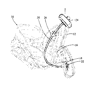
[0019] Fig. 1-is a diagram that illustrates an isometric perspective view of a
step-in snowboard
binding with rear-mounted lever in the unlocked position with a pull cable,
according to an
embodiment of the present disclosure.
[0020] Fig. 2 is a diagram that illustrates an isometric perspective view of a
snowboard binding
with rear-mounted lever in the locked position with a pull cable, according to
an embodiment of
the present disclosure.
[0021] Fig. 3 is a diagram that illustrates an isometric perspective view of a
snowboard binding
with bent rear-mounted lever with a cable channel in the unlocked position
with a pull cable,
according to an embodiment of the present disclosure.
[0022] Fig. 4 is a diagram that illustrates various parts used to attach a
pull cable to a binding
according to embodiments of the present invention.
7
CA 02803441 2015-10-02
[0023] Fig. 5 is a diagram that illustrates an isometric perspective view of a
snowboard binding
with a semi-rigid bendable guide and mounting bracket, according to an
embodiment of the
present disclosure.
[0024] Fig. 6 is a diagram that illustrates an isometric perspective view of a
snowboard binding
with an angled semi-rigid bendable guide and semi-rigid bendable guide cover,
according to an
embodiment of the present disclosure.
[0025] Fig. 7 is a diagram that illustrates an isometric perspective view of a
snowboard binding
with an angled semi-rigid bendable guide, and the grip stored against the toe
end of the binding,
according to an embodiment of the present disclosure.
DETAILED DESCRIPTION
[0026] For the purposes of promoting an understanding of the principles of the
present
disclosure, reference will now be made to the embodiments illustrated in the
drawings and
specific language will be used to describe the same. However, the illustrated
embodiments are
merely exemplary and many additional embodiments of the present disclosure are
possible. For
example, a snowboard binding is pictured; however, the subject matter of the
present disclosure
can be applied to any binding attaching a boot to a sports gear with a rear-
mounted locking lever.
Understood is that no limitation of the scope of the present disclosure is
thereby intended. Any
alterations and further modifications in the illustrated devices, and such
further application of the
principles of the present disclosure, as illustrated herein are contemplated
as would normally
occur to one skilled in the art to which the present disclosure relates, are
also encompassed by
the present disclosure.
8
CA 02803441 2015-10-02
[0027] Unless otherwise indicated, the drawings are intended to be read (e.g.,
arrangement of
parts, proportion, degree, etc.) together with the specification, and are to
be considered a portion
of the entire written description of the present disclosure. As used in the
following description,
the terms "horizontal," "vertical," "left," "right," "up," and "down"; as well
as adjectival and
adverbial derivatives thereof (e.g., "horizontally," "rightwardly,"
"upwardly," etc.) simply refer
to the orientation of the illustrated structure as the particular drawing
figure faces the reader.
Similarly, the terms "inwardly" and "outwardly" generally refer to the
orientation of a surface
relative to its axis of elongation, or axis of rotation, as appropriate.
[0028] The phrases "at least one," "one or more," and "and/or" are open-ended
expressions that
are both conjunctive and disjunctive in operation. For example, each of the
expressions "at least
one of A, B and C", "at least one of A, B, or C", "one or more of A, B, and
C", "one or more of
A, B, or C" and "A, B, and/or C" means A alone, B alone, C alone, A and B
together, A and C
together, B and C together, or A, B and C together. The term "a" or "an"
entity refers to one or
more of that entity. As such, the terms "a" (or "an"), "one or more" and "at
least one" can be
used interchangeably herein. It is also to be noted that the terms
"comprising," "including," and
"having" can be used interchangeably.
1. The Locking Lever Pull Cable
[0029] Shown throughout the figures, the present disclosure generally
describes a pull cable
attached to a rear-mounted locking lever of a snowboard binding.
[0030] Referring to Figure 1, this a diagram illustrates a perspective view of
a common step-in
type snowboard binding with a front toe section (10) and a rear-mounted lever
(14) in the
unlocked position, in accordance with an embodiment of the present disclosure.
The step-in
snowboard binding has a highback (12) that has a locking lever (14) with an
aperture (18) that
9
CA 02803441 2015-10-02
works about a pivot (16) in the vertical direction. A pull cable (20), cord,
rope, pull, strap or
equivalent is attached to the locking lever (14). Such attachment may be by
any means of
securely preventing the pull cable (20) from detaching from the locking lever
(14): as shown the
structure for attachment of the pull cable or strap is a protrusion that may
be a crimp (22) applied
to the end of the pull cable (20) that prevents the pull cable from pulling
through an aperture in
the locking lever (18). The end of the pull cable (20) that is distal from the
locking lever may
have a grip (24), handle, pull, loop, or similar functional element that can
allow the user of the
binding to conveniently grasp the pull cable (20). The pull cable (20) then
threads through a
cable guide (26) that is either molded into, attached directly to, or a
drilled into the highback (12)
of the binding in a position that is off-center from the vertical axis of the
highback (12) and
above the attachment of the pull cable (20) to the locking lever (14). The
cable guide (26) can be
a part of, or mounted to, either side or the center of the top of the
highback. The cable guide (26)
can be made of any material suitable for its purpose, which is preferably
plastic or metal; and
made in any arrangement that allows the pull cable (20) to pass through it and
be directed in
either a forward, an upward, or a forward and upward direction.
[0031] Referring to Figure 2, this a diagram illustrates the same binding and
embodiment of the
invention as Figure 1, except that it illustrates a hand (24) pulling the pull
cable (20) in a forward
and upward manner, thereby closing the locking lever (14), in accordance with
an embodiment
of the present disclosure.
[0032] Still referring to Figure 2, important is that a snowboarder trying to
close the locking
lever on a binding is often balancing on his heels or toes while on a slope.
Stooping down and
reach behind a binding highback while balancing on one's heels or toes is
difficult: the farther a
snowboarder must reach, the more likely he/she is to lose his/her balance and
fall over.
CA 02803441 2015-10-02
[0033] Referring back to Figure 1 and still referring to Figure 2, these
diagrams illustrate several
features, in accordance with an embodiment of the present disclosure. Firstly,
the pull cable (20)
can be semi-rigid; this allows the pull cable (20) to maintain an upright
position against gravity;
this in-turn allows the snowboarder to grasp the grip of the pull cable (24)
from a position that is
higher than the location of the cable guide (26) on the highback (12) of the
binding. If the pull
cable (20) being semi-rigid was not rigid enough to easily support its own
weight and maintain
itself in an upright position it would fall below the height of the cable
guide (26) and highback
(12) and thereby impairing the user's ability to grasp the grip (24) easily.
Additionally, if the
pull cable (20) were too rigid it would become prone to damage and could cause
injury to the
user.
[0034] Still referring back to Figure 1 and still referring to Figure 2,
secondly, the cable guide
(26) is located asymmetrically to the vertical axis of the highback (12) on
the upper end of the
highback. This feature allows the portion of the pull cable (20) that
protrudes above the cable
guide (26) when the rear-mounted locking lever (14) is in the down position to
protrude forward,
to the side, or past the leg of the user; toward the reaching hand of the user
while the user
crouches or leans downward.
[0035] Still referring back to Figure 1 and still referring to Figure 2, step-
in bindings function by
utilizing a rear-mounted locking lever that engages a cable connecting the
pivotable sidewalls
attached to a sole plate, such that the assembly simultaneously moves the
highback and the instep
straps, or other forward locking mechanism, into position about a rider's
boot. Because the
instep straps, or other forward locking mechanism, and highback are tightened
simultaneously;
there is less resistance against the highback when the foot is flexed upwards
towards the shin of
the user. Snowboarders are often balancing on their heels with their front
side facing down the
11
CA 02803441 2015-10-02
slope. Because a snowboarder is balancing on his heels, when he leans forward
or crouches
directly downward, his feet naturally curl upwards toward his shins; thereby
allowing the locking
lever of the binding to be placed in the locked position with less resistance.
Because there is less
resistance to the closure of the binding when pulling directly up or forward
from the
snowboarder's center of balance, less force is required. Because less force is
required, the
movement is quicker and the snowboarder is less likely to lose balance. This
same principle
applies whether the snowboarder is balancing on the toe side or heel side of
the snowboard. This
same principle also allows the present embodiments of the present disclosure
to allow the
snowboard to fasten their binding without sitting down.
[0036] Still referring back to Figure 1 and still referring to Figure 2, when
the pull cable (20) is
located above the cable guide (26) and to the side of the leg, the snowboarder
will pull the pull
cable (20) directly upwards, or forwards, or upwards and forwards from his
center of balance, at
a higher position than reaching for the locking lever without the aid of the
embodiments of the
claimed invention. While the snowboarder is in motion on a ski slope, he can
gently reach to a
convenient location for the pull cable; thereby allowing him to easily secure
the binding while
maintaining balance in an upright position.
[0037] Still referring back to Figure 1 and still referring to Figure 2, the
performance benefits
are clear when considering the alternatives. When balancing on a snowboarder's
heels or toes, it
is more difficult to grasp a pull cable that is behind the foot on the
highback than it is to grasp a
cable or cord that is raised higher and to the side, or in front of the leg;
likewise, without a grip
that one can pull directly upward or forward from one's center of gravity,
maintaining one's
balance becomes much more difficult. Reaching down and behind a snowboarder's
leg to
operate the locking lever additionally causes extension in the angle between
the foot and the
12
CA 02803441 2015-10-02
ankle, creating resistance on the highback that makes it much harder to close
the locking lever.
Extension between the foot and the ankle further increases the likelihood the
snowboarder will
lose his balance and not be able to secure his boot to his binding without
sitting down.
[0038] Still referring back to Figure 1 and still referring to Figure 2,
thirdly, the asymmetrical
location of the cable guide (26) on the highback (12) acts as a pivot point
for the pull cable (20),
thereby decreasing the force necessary for the snowboarder to lock the rear-
mounted lever (14).
Again, the easier it is for the snowboarder to close the locking lever, the
more likely that he will
maintain his balance.
[0039] Still referring back to Figure 1 and still referring to Figure 2,
fourthly, the asymmetrical
location of the cable guide (26) allows the semi-rigid pull cable (20) to be
pulled directly upward
or forward while the snowboarder maintains their center of gravity without
causing the pull cable
to rub against the user's leg causing discomfort or wear to their clothing.
[0040] Still referring back to Figure 1 and still referring to Figure 2,
fifthly, the pull cable (20)
can, and preferably is (when installed as a post market add-on to common step
in bindings as
opposed to built into the binding at the factory), threaded through the
aperture (18) in the rear-
mounted locking lever (14) and over the top of the locking lever when it is in
the locked position
as shown in Figs. 1 and 2. This provides several benefits: (a) it creates a
second pivot point on
the top of the locking lever thereby decreasing the force necessary for the
user to lock the rear-
mounted lever (14); (b) it prevents a pull cable from preventing the closure
of the locking lever
by coming between the locking lever and the highback; and (c) counter-
intuitively, the pivot
point (16) of the locking lever (14) itself aids in the closing of the locking
lever until the locking
lever crosses the horizontal plane at which point the force necessary to close
the locking lever
also increases due to the resistance felt as the binding secures the boot,
having the pull cable loop
13
CA 02803441 2015-10-02
over the thickness of the locking lever allows the pull cable (20) to create
an angle between the
pivot (16) of the locking lever (14) and the pivot point of the cable guide
(26) that achieves
greater mechanical advantage.
[0041] Referring to Figure 3, this diagram illustrates a perspective view of
an alternate
embodiment similar to the embodiment in Figures 1 and 2, with a few new
features, in
accordance with the present disclosure. One of these features is that the
locking lever (32) is
bent above its hinge (16). The bend in the locking lever (32) allows the pull
cable (20) to be
channeled more directly into the cable guide (30), changing the point of wear
on the locking
lever from the side of the locking lever to its top. In the alternative, the
locking lever could be
straight without a bend, but installed with a hinge that is angled toward the
cable guide, which
would reduce angular tension on the locking lever's hinge, directing tension
along the axis
perpendicular to the axle of the hinge, thereby reducing wear on the axle of
the hinge (16).
[0042] Still referring to Figure 3, the use of a lever (32) that has a bulbous
distal end (36) that
serves the same function that the threading of the pull cable (20) over the
locking lever serves, as
explained above. This bulbous distal end (36) can have a channel running
around its outward
facing curve (38) that can cradle the pull cable (20) and keep it pointed
towards the cable guide
(30). In the alternative, the embodiment could include a locking lever (32)
with an aperture (34)
adapted to hold the end of the pull cable (20) at an ideal angle to prevent
wear on the pull cable
from repeated use. Figure 3 also illustrates an alternative bar cable handle
(28).
[0043] Referring to Figure 4, this diagram illustrates a side exploded view of
the cable or pull, in
accordance with an embodiment of the present disclosure. Contemplated is that
the cable or pull
could be made and sold as an aftermarket accessory that users can install onto
existing
snowboard bindings. The cable or pull is so designed that it can either be
built into the binding
14
CA 02803441 2015-10-02
or installed as an aftermarket add-on and possibly still be quickly and easily
moved from one
binding to another. The parts that may be used include: a pull cable (20)
which may optionally
have threaded regions on either end (40); handles such as a rounded disk (24),
or a bar handle
(29), with a region for attachment (28) that can accommodate the pass through
of pull cable (20),
the grip then attached to the semi-rigid pull cable by use of crimps (42) or
by allowing the semi-
rigid pull cable to screw directly into the grip. Depicted are two examples of
a cable guide,
including a stylized version that is lower profile and therefore less likely
to cause injury (30),
with a screw (44), and a threaded socket (31). In Figure 4 one can also find a
cable guide
assembled from a standard threaded ring (26), nut (46), and washer (48)
closure.
2. Method for Attaching the Pull Cable Depicted in Figures I Through 4
[0044] Referring back to Figures I through 4, if a cable guide is not molded
directly into the
highback of the binding, the embodiments of this invention can easily be
installed in virtually
any snowboard binding with a rear-mounted locking lever containing an aperture
with as little as
two simple steps. First, drill a hole into the highback of the binding and
insert a screw (44)
through the highback and into a cable guide (30). Second, thread a semi-rigid
pull cable (20)
with a crimped (42), or otherwise secured, end through the inside of the
aperture of the locking
lever then through the cable guide (30). Finally, attach the grip (28) to the
semi-rigid pull cable
if necessary.
3. Using the Semi-rigid Pull Cable as a Means to Carry a Snowboard
[0045] In one alternative embodiment of the present disclosure (not shown),
the pull cables or
straps have loops on their upward ends in place of, or in addition to,
handles. Such loops are
ideally placed to allow the user to carry their snowboard by placing such
loops around their
shoulders. Carrying the snowboard with such loops allows the board to be
carried with the
CA 02803441 2015-10-02
bindings opened and the flat of the bottom of the board against the flat of
the user's back or
front.
4. Using a Semi-rigid Bendable Guide for a Pull Cable
[0046] Referring to Figure 5, this diagram illustrates a pull or cable that
includes a semi-rigid
bendable guide (52), such as a spring, in accordance with an embodiment of the
present
disclosure. The semi-rigid bendable guide (52) is attached to the highback
(12) with a bracket
(50). In this embodiment, the pull cord (20) has less reason to be semi-rigid
as the semi-rigid
bendable guide can guide the pull cord or strap to a position upward, forward,
or upward and
forward from the highback (12) of the binding. As illustrated, this embodiment
accomplishes
attaching the semi-rigid bendable guide (52) to the highback with one screw
(44) which attaches
a bracket (50) to the highback (12), and a second screw (44) which attaches
the bracket (50) to
the semi-rigid bendable guide (52). The semi-rigid bendable guide (52) is
attached in such a way
that it is directed upwards, forwards, or upwards and forwards towards the
hands of the
snowboarder, situated between the grip (28) and the highback (12). In
alternative embodiments,
the bracket (50) can be: an L-bracket, a straight bracket, a hinge; the semi-
rigid bendable guide
can also be molded to the highback (12), slot or snap into place, or any other
suitable method of
fixing the semi-rigid bendable guide (52) to the highback (12), with any
number of screws or
other articles or methods of attachment. The semi-rigid bendable guide bends
to allow the rider
to continue to pull the pull cord (20) in the upward plain as the rider stands
upward, thereby
allowing the rider to more easily maintain their balance and not have to sit
down.
[0047] Referring to Figure 6, this diagram illustrates a pull or cable that
includes a semi-rigid
bendable guide cover (54) over a curved semi-rigid bendable guide (52) and a
hand pulling
upwards on the grip (28), in accordance with an embodiment of the present
disclosure. The
16
CA 02803441 2015-10-02
semi-rigid bendable guide cover (54) prevents the semi-rigid bendable guide
(52) from becoming
packed up with ice, snow, or mud so that the pull cable (20) continues to
glide effortlessly inside
the semi-rigid bendable guide (54). The angle of the semi-rigid bendable guide
(52) can help to
place the grip in a forward and inward position because it can slightly angle
around the
snowboarder's leg. The angled semi-rigid bendable guide (52) feature makes it
even easier for
the snowboarder to grasp the grip while maintaining a balanced position.
Furthermore, the semi-
rigid bendable guide (52) can also act as a guide to direct the boot into the
binding before the
snowboarder is ready to close the locking lever, whereby the snowboarder need
not even look
down to find the correct horizontal position of the foot for placing it within
the binding.
5. Storing the Pull Cable against the Binding
[0048] Referring to Figure 7, this diagram illustrates a pull or cable that
includes a means to
attach the grip to the toe region of the binding (10), in accordance with an
embodiment of the
present disclosure. The grip (56) contains a magnetic material and another
magnet (58) is
positioned on the toe region of the binding (10) such that the grip (56) and
the magnet (58) are
attracted to each other. The magnetic attachment allows for the easy stowage
of the pull cable
when the snowboarder desires. The magnetic attachment also allows for the
rider to more easily
release the stored pull cable without having to take another unnecessary step
to release the pull
cable. In an alternative embodiment, the grip (56) can be stored in a slot
located on the toe area
of the binding (10).
[0049] All patents and publications are herein incorporated by reference to
the same extent as if
each individual publication was specifically and individually indicated to be
incorporated by
reference.
17
CA 02803441 2015-10-02
[0050] Understood is that, while certain forms of the present disclosure are
illustrated, the
subject matter of the present disclosure is not to be limited to the specific
forms or arrangements
herein described and shown. For example, a spring is used; however, in the
alternative other
semi-rigid bendable guides could be used, such as tubes, connected rigid
pieces, etc. Various
changes may be made without departing from the scope of the present
disclosure; and the present
disclosure is not to be considered limited to what is shown and described in
the specification and
any drawings/figures included herein.
[0051] One skilled in the art will readily appreciate that the subject matter
of the present
disclosure is well-adapted to carry out the objectives and obtain the ends and
advantages
mentioned, as well as those inherent therein. The embodiments, methods,
procedures, and
techniques described herein are presently representative of the preferred
embodiments; are
intended to be exemplary; and are not intended as limitations on the scope.
Changes therein and
other uses will occur to those skilled in the art which are encompassed within
the spirit of the
invention and are defined by the scope of the claims. Although the present
disclosure has been
described in connection with specific preferred embodiments, understood is
that the subject
matter of the present disclosure as claimed should not be unduly limited to
such specific
embodiments. Indeed, various modifications of the described modes for carrying
out the subject
matter of the present disclosure which are obvious to those skilled in the art
are intended to be
within the scope of the claims.
18