Note : Les descriptions sont présentées dans la langue officielle dans laquelle elles ont été soumises.
HOIST ROPE GUIDE
CROSS-REFERENCE TO RELATED APPLICATIONS
[0001] This application claims priority to U.S. Provisional Application No.
61/593,120, filed
on January 31, 2012.
BACKGROUND
[0002] The present invention relates to the field of mining shovels,
Specifically, the present
invention relates to a guide mechanism for a dipper hoist rope.
[0003] Conventional electric rope mining shovels include a boom, a handle
having one end
coupled to the boom, and the other end coupled to a dipper. The dipper is
supported by hoist
ropes that pass over a sheave coupled to the end of the boom. The hoist ropes
are secured to a
winch for paying out and reeling in the ropes. During a digging cycle, the
dipper is raised and
lowered by reeling in and paying out the hoist rope
[00041 As the dipper is hoisted through a bank of material, tension in the
ropes increases. It
is often difficult to directly measure the amount of tension in the ropes,
making it difficult for the
operator to know whether the ropes are slack or under stress. When the hoist
ropes become
slack, the ropes oscillate and wear against the rope guide members and the
boom, thereby
reducing the life of the ropes.
SUMMARY
[0005] In one embodiment, the invention provides a rope guide for a mining
shovel, the
mining shovel including a boom and a rope, the boom including a first end and
a second end, the
rope passing between first end and the second end of the boom. The rope guide
includes an arm
pivotably coupled to the boom. The rope guide further includes a first rope-
contacting element
coupled to the arm, the first rope-contacting element engaging a first portion
of the rope, and a
second rope-contacting element coupled to the arm, the second rope-contacting
element
engaging a second portion of the rope and being spaced a distance from the
first rope-contacting
element. The rope guide also includes a spring damper coupled between the boom
and the arm,
the spring damper biasing the arm to rotate in a first direction about the
first end, the spring
1
CA 2804306 2019-01-15
CA 02804306 2013-01-31
damper generating a biasing force that causes the first rope-contacting
element and the second
rope-contacting element to maintain positive engagement with the rope.
[0006] In another embodiment, the invention provides a rope guide for a
mining shovel, the
mining shovel including a boom and a rope, the boom including a first end and
a second end, the
rope passing between first end and the second end of the boom. The rope guide
includes an arm
pivotably coupled to the boom. The rope guide further includes a rope-
contacting element
coupled to the arm and a spring damper coupled between the boom and the arm.
The spring
damper biases the arm in a first direction to maintain positive engagement
between the rope-
contacting element and the rope.
[0007] Other aspects of the invention will become apparent by consideration
of the detailed
description and accompanying drawings.
BRIEF DESCRIPTION OF THE DRAWINGS
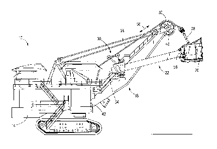
[0008] FIG. 1 is a side view of a mining shovel.
[0009] FIG. 2 is a side view of a rope guide according to one embodiment of
the invention,
with the hoist rope in a slack state.
[0010] FIG. 3 is a side view of the rope guide of FIG. 2 with the hoist
rope in a taut state.
[0011] FIG 4 is a side view of a rope guide according to another embodiment
of the
invention, with the hoist rope in a slack state.
[0012] FIG. 5 is a side view of a rope guide according to another
embodiment, with the hoist
rope in a slack state.
[0013] FIG. 6 is a side view of a rope guide according to another
embodiment, with the hoist
rope in a taut state.
[0014] FIG. 7 is a schematic view of a mining shovel according to another
embodiment, with
the hoist rope in a taut state.
2
CA 02804306 2013-01-31
[0015] FIG. 8 is a schematic view of the mining shovel of FIG. 7, with the
hoist rope in a
slack state.
[0016] Before any embodiments of the invention are explained in detail, it
is to be
understood that the invention is not limited in its application to the details
of construction and the
arrangement of components set forth in the following description or
illustrated in the following
drawings. The invention is capable of other embodiments and of being practiced
or of being
carried out in various ways. Also, it is to be understood that the phraseology
and terminology
used herein is for the purpose of description and should not be regarded as
limiting.
DETAILED DESCRIPTION
[0017] As shown in FIG. 1, a mining shovel 10 includes a base 14, a boom
18, a handle 22, a
dipper 26, a bail 28, and a rope guide 30. The base 14 includes a winch (such
as winch 51
illustrated schematically in the embodiment of FIG. 7) for reeling in and
paying out a hoist cable,
or rope 38. The boom 18 includes a first end 42 coupled to the base 14, a
second end 46
opposite the first end 42, and a boom sheave 50. The boom sheave 50 is coupled
to the second
end 46 of the boom 18 and guides the rope 38 over the second end 46. The
handle 22 includes a
first end 54 and a second end 56. The first end 54 of the handle 22 is
moveably coupled to the
boom 18 at a position between the first end 42 and the second end 46 of the
boom 18. The
second end 56 of the handle 22 is pivotably coupled to the dipper 26. The rope
38 passing over
the boom sheave 50 is coupled to and supports the dipper 26. As the rope 38 is
reeled in by the
winch, the dipper 26 is raised; as the rope 38 is paid out, the dipper 26 is
lowered. The rope 38
passing between the winch and the boom sheave 50 defines a direction of travel
58, and the rope
38 in this portion passes through the rope guide 30.
[0018] As shown in FIGS. 2 and 3, the rope guide 30 includes an arm 66, a
first rope-
contacting element 70, a second rope-contacting element 74, and a spring
damper 82. In the
illustrated embodiment, the arm 66 has a triangular shape formed by three
members 66a, 66b,
66c and includes a first end 86, a second end 90, and a third end 94. The
third end 94 of the arm
66 is pivotably coupled to the boom 18. In other embodiments, the arm 66
includes fewer or
more members, such as two members coupled together at one end spaced apart by
a fixed angle
at opposite ends.
3
CA 02804306 2013-01-31
[0019] In the illustrated embodiment, the first rope-contacting element 70
and the second
rope-contacting element 74 are sheaves. The first sheave 70 is pivotably
coupled to the first end
86 of the arm 66 at a pivot point 96, and the second sheave 74 is pivotably
coupled to the second
end 90 at a pivot point 98. The first sheave 70 and the second sheave 74 are
spaced apart by a
distance D1 (as measured between the pivot points 96, 98) such that the rope
38 passes over the
first sheave 70 and under the second sheave 74. In the illustrated embodiment,
the distance D1 is
a fixed distance of approximately 48 inches; however, in further embodiments
the distance may
be between approximately 36 inches and 72 inches.
[0020] In the illustrated embodiment, the first sheave 70 is offset from
the second sheave 74
by an angle 106 as measured from the point about which the arm 66 rotates
(i.e., the third end
94) between arm members 66b and 66c. The angle 106 is dependent on the
distance D1, and is
approximately 40 degrees; however, in further embodiments the angle may be
between
approximately 30 degrees and 60 degrees. When the rope 38 is taut (FIG. 3),
the first sheave 70
and the second sheave 74 are offset by a horizontal distance and are not
directly in line with one
another. In other embodiments, the rope-contacting elements are rollers, other
elements that
allow movement of the rope, or the like.
[0021] The spring-damper 82 is coupled between the arm 66 and the boom 18.
In the
illustrated embodiment, the spring-damper 82 includes a compression spring 110
and a dashpot
112. The compression spring 110 biases the arm 66 to pivot in a first
direction 114, applying a
pre-load on the rope 38 in a direction substantially perpendicular to the
direction of travel 58 of
the rope 38. The dashpot 112 resists the motion of the arm 66 in order to
dampen the response
behavior of the arm 66 as the rope tension changes. In other embodiments,
other types of springs
and spring-dampers are used, such as a rotary-type spring damper, utilizing,
for example, a
torsional spring and a rotary damper element.
[0022] FIGS. 2 and 3 illustrate the motion of the rope guide 30 during
various rope tension
conditions. When the rope 38 is slack, as shown in FIG. 2, the compression
spring 110 biases
the arm 66 and causes the arm 66 to rotate in the first direction 114 (counter
clockwise as shown
in FIG. 2). Rotation of the arm 66 effectively increases the length that the
rope 38 must travel
between the base 14 and the boom sheave 50. The first sheave 70 and the second
sheave 74
4
CA 02804306 2013-01-31
remain in positive engagement with the rope 38, taking up the slack and
maintaining a nominal
tension in the rope 38. Referring to FIG. 3, as the rope 38 becomes taut,
tension in the rope 38
increases and resists the biasing force of the compression spring 110. The arm
66 rotates against
the spring 110 in a second direction 118 (clockwise as shown in FIG. 3).
[0023] FIG. 4 illustrates a rope guide 130 according to another embodiment
of the invention.
In the illustrated embodiment, the arm member 66a of the rope guide 130 is
adjustable in length
via an adjustment mechanism 67. The illustrated adjustment mechanism 67 is a
screw element,
though in further embodiments other structures are also possible, including
use of pins, notches,
and/or a plurality of telescoping segments. The adjustment mechanism 67
permits the distance
D1 between sheaves 70, 74 to be altered, such that a pre-loaded tension within
the rope 38 may
be fine-tuned. For example, decreasing the length of arm member 66a creates
higher pre-loaded
tension in the rope 38. Alternatively, increasing the length of arm member 66a
creates lower
pre-loaded tension in the rope 38. Fine tuning of the distance D1 is used to
reduce rope
oscillations.
[0024] FIG. 5 illustrates a rope guide 230 according to another embodiment
of the invention.
In the illustrated embodiment, the arm member 66a includes a vibration
dampener 68. The
vibration dampener 68 permits the length D1 between sheaves 70, 74 to vary in
the presence of
energy vibration. The vibration dampener 68 absorbs vibrational energy caused
by the tension in
the rope, and reduces rope oscillations.
[0025] FIG. 6 illustrates a rope guide 330 according to another embodiment
of the invention
that includes one sheave. Rotation of the sheave 70 increases the length of
travel between the
winch and the boom sheave 50, taking up slack in the hoist rope 38, and
thereby reducing
oscillations in the rope 38. The arm member 66c is longer than arm member 66c
illustrated in
the two-sheave configuration of FIGS. 2-3. With a longer arm member 66c, the
single sheave
configuration takes up as much slack in the rope 38 as the two-sheave
configuration.
[0026] FIG. 7 is a schematic illustration of another embodiment of a mining
shovel 110 that
includes a rope guide 430 having a single sheave 70. The rope guide 430 is
positioned
approximately halfway between winch 51 and the boom sheave 50. The rope guides
30, 130,
230, and 330 illustrated in FIGS. 1-6 are also positioned approximately
halfway between a winch
CA 02804306 2013-01-31
and boom sheave 50, though other locations are also possible for the rope
guides 30, 130, 230,
330, 430. FIG. 7 further illustrates a stabilizing arm 111. The stabilizing
arm 111 is a rigid
structure positioned along the boom 18, and prevents the arm member 66c from
rotating past a
predetermined angle.
[0027] In yet further embodiments, the rope guide 30 may be used in
combination with a
fleeting sheave rope guide, such as the type described in U.S. Patent No.
7,024,806.
[0028] By providing positive engagement of the sheave(s) 70, 74 with the
rope 38, the rope
guides reduce slack in the rope 38, which in turn reduces the oscillation and
wear on the rope 38,
improving overall life of the rope 38 and the associated components.
Furthermore, the rope
guides provide a mechanism for determining the rope tension.
[0029] The rope guides are modeled as mass-spring-damper systems in which
the rope
tension provides an input force. For example, as illustrated in FIGS. 2-7, a
sensor 124 is
positioned near the arm 66. The sensor 124 detects an angle of rotation 122 of
the arm 66 or arm
member 66c with respect to the boom 18. The sensor 124 is in communication
with a controller
126 (illustrated schematically in FIGS. 2-7). The sensor 124 sends a signal to
the controller 126.
By measuring the angle of rotation 122 with the sensor 124, it is possible for
the controller 126
to calculate the angular velocity and angular acceleration of the arm 66 or
arm member 66c.
Applying principles of vibrational mechanics, these values can be used to
calculate the force
acting on the arm 66 or arm member 66c, which in turn provides the tension in
the rope 38. In
some embodiments, other characteristics of the rope guide 30 beside the angle
of rotation 122
with respect to the boom 18 may be used to determine the rope tension. Based
on the calculated
rope tension, the controller 126 determines the available drive speed and
torque that can be
applied to the rope 38 via the winch 51 by an operator. For example, if the
controller 126
determines that the rope tension is below a predetermined level (i.e. the rope
is slack), the
controller 126 reduces the available speed and torque to the rope that can be
applied by the
operator. In some embodiments, the available drive speed and torque applied to
the rope can be
reduced by as much as 90%, such that the operator can apply only up to 10% of
the total drive
speed and torque to the rope while the rope is slack. Other amounts of
available drive speed and
torque are also possible.
6
CA 02804306 2013-01-31
[0030] This type of control helps to inhibit high impact loading on the
boom 18. For
example, and with reference to FIGS. 7 and 8, if a rope 38 is slack (FIG. 8),
rather than taut
(FIG. 7), the boom 18 will tend to pivot and lie down. If the operator were to
apply full speed
and torque to the rope 38 via the winch 51 while the rope 38 was slack, this
would impart a
dynamic impact load (i.e. a "snapping" action of the rope and boom 18), which
could potentially
damage one or more components of the overall mining shovel 10. Incorporating a
rope guide
with sensor 124 and controller 126 helps to alleviate this potential problem.
[0031] Thus, the invention provides, among other things, a rope guide for a
mining shovel.
Although the invention has been described in detail with reference to certain
preferred
embodiments, variations and modifications exist within the scope and spirit of
one or more
independent aspects of the invention as described.
7