Note : Les descriptions sont présentées dans la langue officielle dans laquelle elles ont été soumises.
CA 02805955 2013-01-18
WO 2012/010897
PCT/GB2011/051377
1
A Safety Mechanism for a Well, a Well Comprising the Safety
Mechanism and related Methods
This invention relates to a safety mechanism, such as a valve, sleeve, packer
.. or plug, for a well; a well comprising the safety mechanism; and methods to
improve the safety of wells; particularly but not exclusively subsea
hydrocarbon wells.
In recent years, oil and gas has been recovered from subsea wells in very
deep water, of the order of over lkm. This poses many technical problems in
drilling, securing, extracting and abandoning wells in such depths.
In the event of a failure in the integrity of the well, wellhead apparatus
control
systems are known to shut the well off to prevent dangerous blow-out, or
significant hydrocarbon loss from the well. Blow-out-preventers (B0Ps) are
situated at the top of subsea wells, at the seabed, and can be activated from
a control room to shut the well, or may be adapted to detect a blow-out and
shut automatically. Should this fail, a remotely operated vehicle (ROV) can
directly activate the BOP at the seabed to shut the well.
In a completed well, rather than a BOP, a "Christmas" tree is provided at the
top of the well and a subsurface safety valve (SSV) is normally added,
"downhole" in the well. The SSV is normally activated to close and shut the
well if it loses communication with the controlling platform, rig or vessel.
Despite these known safety controls, accidents still occur and a recent
example is the disastrous blow-out from such a subsea well in the Gulf of
Mexico, causing a massive explosion resulting in loss of life, loss of the rig
2
a significant and sustained escape of oil into the Gulf of Mexico, threatening
wildlife and marine
industries.
Whilst the specific causes of the disaster are, at present, unclear, some
aspects can be observed:
an Emergency Dis-connect System (EDS) controlled from the rig failed to seal
and disconnect
the vessel from the well; a dead-man/AMF system at the seabed failed to seal
the well;
subsequent Remotely Operated Vehicle (ROV) intervention also failed to
activate the safety
mechanisms on the BOP. Clearly the conventional systems focused primarily on
the blow-out-
preventer did not activate at the time of the blow-out and also failed to stem
the tide of oil into the
sea after control communication was lost with the rig.
Thus there is a need to improve the safety of oil wells especially those
situated in deep water
regions.
SUMMARY
In one aspect, the present invention provides a well comprising:
a blowout preventer (BOP) positioned on a top of the well; and
a safety mechanism, the safety mechanism comprising:
an obstructing member moveable between a first position where fluid flow is
permitted, and a
second position where fluid flow from the well is restricted;
a movement mechanism;
and a wireless receiver, adapted to receive a wireless signal;
wherein the movement mechanism is operable to move the obstructing member from
one of the
first and second positions to the other of the first and second positions in
response to a change
in the signal being received by the wireless receiver; and
wherein the movement mechanism is adapted to move the obstructing member from
one of the
first and second positions to the other of the first and second positions
automatically in response
to at least one level of a parameter detected by a sensor; and wherein the
level of the parameter
at which the movement mechanism is adapted to move the obstructing member
to/from the first
position from/to the second position is variable by an operator, and wherein
the safety mechanism
comprises, one of:
CA 2805955 2018-04-05
2a
(i) a valve on an elongate member, the valve positioned below the BOP; and
wherein in the
second position, the obstructing member stops fluid flow through a main
longitudinal bore of the
elongate member in order to shut the well downhole;
(ii) a packer and expansion mechanism in an annulus below the BOP formed
between two
elongated members, or an elongated member and a wall of the well, wherein the
movement
mechanism causes the expansion mechanism to activate which expands the packer
and so
moves the packer between said first position and said second position; wherein
in the second
position, fluid flow in a main longitudinal direction through the annulus is
resisted.
In another aspect, it is provided a safety mechanism for a well, the safety
mechanism comprising:
(i) an obstructing member moveable between a first position where fluid flow
is permitted,
and a second position where fluid flow is restricted;
(ii) a movement mechanism;
(iii) and a wireless receiver positionable in the well, the wireless receiver
adapted to
receive a wireless signal below a blowout preventer (BOP) positioned on a top
of the well,
wherein the safety mechanism is positioned below the BOP;
wherein the movement mechanism is operable to move the obstructing member from
one
of the first and second positions to the other of the first and second
positions in response to a
change in the signal being received by the wireless receiver; and
wherein the movement mechanism is adapted to move the obstructing member from
one
of the first and second positions to the other of the first and second
positions automatically in
response to at least one level of a parameter detected by a sensor which is
indicative of an
emergency situation; and
wherein the safety mechanism is a pre-production downhole safety mechanism
with the
level of the parameter at which the movement mechanism is adapted to move the
obstructing
member to/from the first position from/to the second position being variable
by an operator from
a first trip point in a first phase when the BOP is in use, the first phase
selected from the group
consisting of:
drilling, suspension, injection, completion and abandonment phases,
and a second trip point in a second phase, the second phase being different
from the first
phase, and selected from the group consisting of: drilling, suspension,
production, injection,
completion and abandonment phases.
CA 2805955 2018-04-05
2b
In yet another aspect it is provided a safety mechanism for a well, the safety
mechanism
comprising:
a pre-production safety valve with a sleeve moveable between a first position
where fluid flow is permitted and a second position where fluid flow is
restricted;
a movement mechanism;
and a wireless receiver positionable in the well, the wireless receiver
adapted to receive
a wireless signal below a blowout preventer (BOP) positioned on a top of the
well, wherein the
valve is positioned below the BOP;
wherein the movement mechanism is operable to move the sleeve from one of the
first
and second positions to the other of the first and second positions in
response to a change in the
signal being received by the wireless receiver;
wherein the movement mechanism is adapted to move the sleeve from one of the
first and
second positions to the other of the first and second positions automatically
in response to at least
one level of a parameter detected by a sensor; and wherein the level of the
parameter at which
the movement mechanism is adapted to move the sleeve to/from the first
position from/to the
second position is variable by an operator.
This summary of the invention does not necessarily describe all features of
the invention.
DESCRIPTION
Given the difficulty in communicating and controlling downhole tools (that is
tools in the well),
especially where communications are severed, one might consider the provision
of a further shut
off mechanism with the BOP situated at the seabed. However the inventors of
the present
invention have noted that the addition of more equipment at this point will be
extremely difficult
because it will increase the size and height of the components placed at this
point, which
immediately prior to installation, will be difficult for rigs to accommodate.
Moreover, whilst this
would add a further protective measure, it is largely the same concept as the
existing safety
systems. Indeed, increasing the complexity of the control systems to support
these additional
features may potentially have a detrimental impact on reliability of the over-
all system rather than
increasing the level of safety provided.
CA 2805955 2018-04-05
CA 02805955 2013-01-18
WO 2012/010897
PCT/GB2011/051377
3
In the case of adding a further conventional control mechanism for devices,
such as a valve, or sensor downhole; the inventors of the present invention
also note limitations since, in the event of a blow-out, the ability to
function
.. these devices may be lost due to the inability to fluctuate pressure to
control
pressure activated devices, or due to the loss of control lines.
Thus it is difficult for a skilled person to design a further safety system
which
can practically add to the safety systems already provided in oil wells.
An object of the present invention is to mitigate problems with the prior art,
and preferably to improve the safety of wells.
According to a first aspect of the present invention there is provided a
safety
.. mechanism comprising:
an obstructing member moveable between, normally from, a first position
where fluid flow is permitted, and, normally to, a second position where fluid
flow is restricted;
a movement mechanism;
and a wireless receiver normally a transceiver, adapted to receive, and
normally transmit, a wireless signal;
wherein the movement mechanism is operable to move the obstructing
member from one of the first and second positions to the other of the first
and
second positions in response to a change in the signal being received by the
wireless transceiver.
The obstructing member can in certain embodiments therefore start at either
the first or second positions.
CA 02805955 2013-01-18
WO 2012/010897
PCT/GB2011/051377
4
The transceiver, where it provided, is normally a single device with a
receiver
functionality and a transmitter functionality; but in principle a separate
receiver
and a separate transmitter device may be provided. These are nonetheless
considered to be a transceiver as described herein when the are provided
together at one location.
Relays and repeaters may be provided to facilitate transmission of the
wireless signals from one location to another.
The invention also provides a well comprising at least one safety mechanism
according to the first aspect of the invention.
Typically the well has a wellhead.
Thus the present invention provides a significant benefit in that it can move,
normally shut, an obstructing member, such as a valve, packer, sleeve or
plug in response to a wireless signal. Significantly this is independent of
the
provision of control lines, such as hydraulic or electric lines, between a
well
and a wellhead apparatus, for example the BOP. Thus in the event of a
disastrous blowout or explosion, a wireless signal can be sent to the valve
merely by contacting the wellhead apparatus typically at the top of the well
with a wireless transmitter, which will send the appropriate signal. For
certain
embodiments the wireless transmitter may be mounted onto the wellhead
apparatus. Indeed this can be achieved even if the wellhead apparatus has
suffered extensive damage, and/or the hydraulic, electric and other control
lines have been damaged and the conventional safety systems have lost all
functionality, since the wireless signal requires no intact control lines in
order
CA 02805955 2013-01-18
WO 2012/010897
PCT/GB2011/051377
to shut off the valve. Thus this removes the present dependence on a
functioning BOP/wellhead apparatus to prevent the egress of oil, gas or other
well fluids into the sea.
5 In certain embodiments the transmitter may be provided as part of a
wellhead
apparatus.
Wellhead apparatus as used herein includes but is not limited to a wellhead,
tubing and/or casing hanger, a BOP, wireline/coiled tubing lubricator, guide
base, well tree, tree frame, well cap, dust cap and/or well canopy.
Typically the wellhead provides a sealing interface at the top of the
borehole.
Typically any piece of equipment or apparatus at or up to 20 ¨ 30m above the
wellhead can be considered for the present purposes as wellhead apparatus.
Said "change in the signal" can be a different signal received, or may be
receiving the control signal where no control signal was previously received
and may also be loss of a signal where one was previously received. Thus in
the latter case the safety mechanism may be adapted to operate when
wireless communication is lost which may occur as a consequence of an
emergency situation, rather then necessarily requiring a control signal
positively sent to operate the safety mechanism.
Indeed the invention more generally provides a transceiver configured to
activate and send signals after an emergency situation has occurred as
defined herein.
CA 02805955 2013-01-18
WO 2012/010897
PCT/GB2011/051377
6
In preferred embodiments the transceiver is an acoustic transceiver and the
control signal is an acoustic control signal. In alternative embodiments, the
transceiver may be an electromagnetic transceiver, and the signal an
electromagnetic signal. Combinations may be provided ¨ for example part of
.. the distance may be travelled by an acoustic signal, part by an
electromagnetic signal, part by an electric cable, and/or part from a fibre
optic
cable; all with transceivers as necessary.
The acoustic signals may be sent through elongate members or through well
fluid, or a combination of both. To send acoustic signals through the fluid, a
pressure pulser or mud pulser may be used.
Preferably the obstructing member moves from the first to the second
position.
Preferably the safety mechanism incorporates a battery.
The safety mechanism is typically deployed subsea.
The transceiver comprises a transmitter and a receiver. The provision of a
transmitter allows signals to be sent from the safety mechanism to a
controller, such as acknowledgement of a control signal or confirmation of
activation.
The safety mechanism may be provided on a drill string, completion string,
casing string or any other elongate member or on a sub-assembly within a
cased or uncased section of the well. The safety mechanism may be used in
CA 02805955 2013-01-18
WO 2012/010897
PCT/GB2011/051377
7
the same wells as a BOP or a wellhead, tree, or well-cap and may be
provided in addition to a conventional subsurface safety valve.
Typically a plurality of safety mechanisms are provided.
The transceiver may be spaced apart from the movement mechanism and
connected by conventional means such as hydraulic line or electric cable.
This allows the wireless signal to be transmitted over a smaller distance. For
example the wireless signal can be transmitted from the wellhead apparatus
to a transceiver up to 100m, sometimes less than 50m, or less than 20m
below the top of the well which is connected though hydraulics or electric
cabling to the obstructing member. This allows the safety mechanism in
accordance with the present invention to operate even when the wellhead,
wellhead apparatus or the top 100m, 50m or 20m of the well is damaged and
control lines therein broken. Thus the benefits of embodiments can be
focused on a particular areas. Accordingly embodiments of the present
invention can be combined with fluid and/or electric control systems.
Preferably a sensor is provided to detect a parameter in the well, preferably
in
the vicinity of the safety mechanism.
Thus such sensors can provide important information on the environment in
all parts of the well especially around the safety mechanism and the data
from the sensors may provide information to an operator of an emergency
situation that may be occurring or about to occur and may need intervention
to mitigate the emergency situation.
CA 02805955 2013-01-18
WO 2012/010897
PCT/GB2011/051377
Preferably the information is retrieved wirelessly, although other means, such
as data cables, may be used. Preferably therefore the safety mechanism
comprises a wireless transmitter, and more preferably a wireless transceiver.
The sensors may sense any parameter and so be any type of sensor
including but not necessarily limited to temperature, acceleration, vibration,
torque, movement, motion, cement integrity, pressure, direction and
inclination, load, various tubular/casing angles, corrosion and erosion,
radiation, noise, magnetism, seismic movements, stresses and strains on
tubular/casings including twisting, shearing, compressions, expansion,
buckling and any form of deformation; chemical or radioactive tracer
detection; fluid identification such as hydrate, wax and sand production; and
fluid properties such as (but not limited to) flow, density, water cut, pH and
viscosity. The sensors may be imaging, mapping and/or scanning devices
such as, but not limited to, camera, video, infra-red, magnetic resonance,
acoustic, ultra-sound, electrical, optical, impedance and capacitance.
Furthermore the sensors may be adapted to induce the signal or parameter
detected by the incorporation of suitable transmitters and mechanisms.
The sensors may also sense the status of equipment within the well, for
example valve position or motor rotation.
The wireless transceiver may be incorporated within the sensor, valve or
safety mechanism or may be independent from it and connected thereto. The
sensors may be incorporated directly in the equipment comprising the
transmitters or may transfer data to said equipment using cables or short-
range wireless (e.g. inductive) communication techniques. Short range is
typically less than 5m apart, often less than 3m apart and indeed may be less
than lm apart.
CA 02805955 2013-01-18
WO 2012/010897
PCT/GB2011/051377
9
The sensors need to operate only in an emergency situation but can also
provide details on different parameters at any time. The sensors can be
useful for cement tests, testing pressures on either side of packers, sleeves,
valves or obstructions and wellhead pressure tests and generally for well
information and monitoring from any location in the well.
The wireless signals may be sent retroactively, that is after an emergency
situation has occurred, for example after a blow out.
Typically the sensors can store data for later retrieval and are capable of
transmitting it.
The safety mechanism may be adapted to move the obstructing member
to/from the first position from/to the second position automatically in
response
to a parameter detected by the sensor. Thus at a certain "trip point" the
safety mechanism can close the well, if for example, it detects a parameter
indicative of unusual data or an emergency situation. Preferably the safety
mechanism is adapted to function in such a manner in response to a plurality
of different parameters all detecting unusual data, thus suggesting an
emergency situation. The parameter may be any parameter detected by the
sensor, such as pressure, temperature, flow, noise, or indeed the absence of
flow or noise for example.
Such safety mechanisms are particularly useful during all phases when a
BOP is in use and especially during non-drilling phases when a BOP is in
use.
CA 02805955 2013-01-18
WO 2012/010897
PCT/GB2011/051377
Preferably the trip point can be varied by sending instructions to a receiver
coupled to (not necessarily physically connected thereto) or integral with,
the
sensors and/or safety mechanism. Such embodiments can be of great
benefit to the operator, since the different operations downhole can naturally
5 experience different parameters which may be safe in one phase but
indicative of an emergency situation in another phase. Rather than setting
the trip point at the maximum safety level for all phases, they can be changed
by communications including wireless communication for the different phases.
For example, during a drilling phase the vibration sensed would be expected
10 to be relatively high compared to other phases. Sensing vibration to the
same extent in other phases may be indicative of an emergency situation and
the safety mechanism instructed to change their trip point after the drilling
phase.
For certain embodiments, a sensor is provided above and below the safety
mechanisms and can thus monitor differential parameters in these positions
which can in turn elicit information on the safety of the well. In particular
any
pressure differential detected across an activated safety mechanism would be
of particular use in assessing the safety of the well especially on occasions
where a controlling surface vessel moves away for a period of time and then
returns.
Sensors and/or transceivers may also be provided in casing annuli.
In use, an operator can react to any abnormal and potentially dangerous
occurrence which the sensors detect. This can be a variety of different
parameters including pressure, temperature and also others like stress and
CA 02805955 2013-01-18
WO 2012/010897
PCT/GB2011/051377
11
strain on pipes or any other parameters/sensors referred to herein but not
limited to those.
Moreover with a plurality of sensors, the data may provide a profile of the
parameters (for example, pressure/temperature) along the casing and so aid
identification where the loss of integrity has occurred, e.g. whether the
casing,
casing cement, float collar or seal assembly have failed to isolate the
reservoir or well. Such information can allow the operator to react in a
quick,
safe and efficient manner; alternatively the safety mechanism can be adapted
to activate in response to certain detected parameters or combination of
parameters, especially where two or three parameters are showing unusual
values.
Such a system may be activated in response to an emergency situation.
Thus the invention provides a method of inhibiting fluid flow from a well in
an
emergency situation, the method comprising:
in the event of an emergency, sending a wireless signal into the well to a
safety mechanism according to the first aspect of the invention.
Preferred and other optional features of the previous embodiment are
preferred and optional features of the method according to the invention
immediately above.
An emergency or emergency situation is where uncontrolled fluid flow occurs
or is expected to occur, from a well; where an unintended explosion occurs or
there is an unacceptable risk that it may occur, where significant structural
damage of the well integrity is occurring or there is an unacceptable risk
that it
CA 02805955 2013-01-18
WO 2012/010897
PCT/GB2011/051377
12
may occur, or where human life, or the environment is in danger, or there is
an unacceptable risk that it maybe in danger. These dangers and risks may
be caused by a number of factors, such as the well conditions, as well as
other factors, such as severe weather.
Thus normally an emergency situation is one where at least one of a BOP
and subsurface safety valve would be attempted to be activated, especially
before/during or after an uncontrolled event in a well.
Furthermore, normally an emergency situation according to the present
invention is one defined as the least, more or most severe accordingly to the
!ADAC Deepwater Well Control Guidelines, Third Printing including
Supplement 2000, section 4.1.2. Thus events which relate to kick control
may be regarded as an emergency situation according to the present
invention, and especially events relating to an underground blowout are
regarded as an emergency situation according to the present invention, and
even more especially events relating to a loss of control of the well at the
sea
floor (if a subsea well) or the surface is even more especially an emergency
according to the present invention.
Methods in accordance with the present invention may also be conducted
after said emergency and so may be performed in response thereto, acting
retroactively.
The method may be provided during all stages of the drilling, cementing,
development, completion, operation, suspension and abandonment of the
well. Preferably the method is provided during a phase where a BOP is
provided on the well.
CA 02805955 2013-01-18
WO 2012/010897
PCT/GB2011/051377
13
Optionally the method is conducted during operations on the well when
attempts have been made to activate the BOP.
During these phases, embodiments of the present invention are particularly
useful because the provision of physical control lines during these phases
would obstruct the many well operations occurring at this time; and indeed
the accepted practice is to avoid as much as possible installing devices which
require communication for this reason. Embodiments of the present invention
go against this practice and overcome the disadvantages by providing
wireless communications. Thus an advantage of embodiments of this
invention is that they enable the use of a safety valve or barrier in
situations
where conventional safety valves or barriers could not, or would not, normally
be deployed.
The safety mechanism may comprise a valve, preferably a ball or flapper
valve, preferably the valve may incorporate a mechanical over-ride controlled,
for example, by pressure, wireline, or coiled tubing or other intervention
methods. The valve may incorporate a 'pump through' facility to permit flow in
one direction.
The obstructing member of the safety mechanism may be a sleeve.
Optionally the safety mechanism may be actuated directly using a motor but
alternatively or additionally may be adapted to actuate using stored pressure,
or preferably using well pressure acting against an atmospheric chamber,
optionally used in conjunction with a spring actuator.
CA 02805955 2013-01-18
WO 2012/010897
PCT/GB2011/051377
14
The safety mechanism may incorporate components which are replaceable,
or incorporate key parts, such as batteries, or valve bodies which are
replaceable without removing the whole component from the well. This can
be achieved using methods such as side-pockets or replaceable inserts,
using conventional methods such as wireline or coiled-tubing.
In order to retrieve data from the sensors and/or actuate the safety
mechanism, one option is to deploy a probe. A variety of means may be
used to deploy the probe, such as an electric line, slick line wire, coiled
tubing, pipe or any other elongate member. Such a probe could alternatively
or additionally be adapted to send signals. Indeed such a probe may be
deployed into a casing annulus if required.
In other embodiments, the wireless signal may be sent from a device
provided at the wellhead apparatus or proximate thereto, that is normally
within 300m. In one embodiment wireless signals can be sent from a
platform, optionally with wireless repeaters provided on risers and/or
downhole. For other embodiments, the wireless signals can be sent from the
seabed wellhead apparatus, after receiving sonar signals from the surface or
from an ROV. In other embodiments, the wireless signals can be sent from
the wellhead apparatus after receiving a satellite signals from another
location. Furthermore if the wellhead is a seabed wellhead, the wireless
signals can be then sent from the seabed wellhead apparatus, after receiving
sonar signals, which had been triggered/activated after receiving a satellite
signal from another location.
The surface or surface facility may be for example a nearby production
facility
standby or supply vessel or a buoy.
CA 02805955 2013-01-18
WO 2012/010897
PCT/GB2011/051377
Thus the device comprises a wireless transmitter, or transceiver and
preferably also comprises a sonar receiver, to receive signals from a surface
facility and especially a sonar transceiver so that it can communicate two-way
5 with the surface facility. For certain embodiments an electric line may
be run
into a well and the wireless transceiver attached towards one end of the line.
In other embodiments the signal may be sent from an ROV via a hot-stab
connection or via a sonar signal from the ROV.
10 Therefore the invention also provides a device, in use fitted or retro-
fitted to a
top of a well, comprising a wireless transmitter and a sonar receiver;
especially for use in an emergency situation.
The device is relatively small, typically being less than 1m3, preferably less
15 than 0.25 m3, especially less that 0.10 m3and so can be easily landed on
the
wellhead apparatus. The resulting physical contact between the wellhead
apparatus and the device provides a connection to the well for transmission
of the wireless signal. In alternative embodiments the device is built into
the
wellhead apparatus, which is often at the seabed but may be on land for a
land well.
Thus such devices also operate wirelessly and do not require physical
communication between the wellhead apparatus and a controlling station,
such as a vessel or rig.
Embodiments of the invention also include a satellite device comprising a
sonar transceiver and a satellite communication device. Such embodiments
can communicate with the well, such as with said device at the wellhead
CA 02805955 2013-01-18
WO 2012/010897
PCT/GB2011/051377
16
apparatus in accordance with a previous aspect of the invention, and relay
signals onwards via satellite. The satellite device may be provided on a rig
or
vessel or a buoy.
Thus according to one aspect of the invention there is provided a well
apparatus comprising a well and a satellite device comprising a satellite
communication mechanism, and a sonar, the device configured to relay
information received from the sonar by satellite.
Preferably the device is independent of the rig, for example it may be
provided on a buoy. Thus in the event that the rig is lost, the buoy may relay
a control signal from a satellite to the well to shut down the well.
In a further embodiment the device at the wellhead apparatus may be wired
.. to a surface or remote facility. Preferably however, the device is provided
with further wireless communication options for communication with the
surface facility. Typically the device has batteries to permit operation in
the
event of damage to the cable.
.. The safety mechanism may comprise a subsurface safety valve, optionally of
known type, along with a wireless transceiver.
In alternative embodiments, the safety mechanism comprises a packer and
an expansion mechanism. The movement mechanism causes the expansion
mechanism to activate which expands the packer and so moving the packer
from said first position to said second position.
CA 02805955 2013-01-18
WO 2012/010897
PCT/GB2011/051377
17
Thus according to a further aspect of the present invention there is provided
a
packer apparatus comprising a packer and an activation mechanism, the
activation mechanism comprising an expansion mechanism for expanding the
packer and a wireless transceiver adapted to receive a wireless control signal
and control the activation mechanism.
The wireless signal is preferably an acoustic signal and may travel through
elongate members and/or well fluid.
Alternatively the wireless signal may be an electromagnetic or any other
wireless signal or any combination of that and acoustic.
References throughout to "expanding" and "expansion mechanisms" etc
include expanding a packer by compression of an elastomeric element and/or
inflating a packer and inflation mechanisms etc and/or explosive activation
with explosive mechanisms, or actuation of a swell mechanism by exposure
of a swellable element to an activating fluid, such as water or oil.
The packer apparatus may be provided downhole in any suitable location,
such as on a drill string or production tubing and, surprisingly, in a casing
annulus between two different casing strings, or between the casing and
formation or on a sub-assembly within a cased or uncased section of the well.
In use after deployment and wireless activation downhole according to the
present invention, the packer may be provided in the expanded state to
provide a further barrier against fluid movement therepast, especially those
provided on an outer face of an elongate member in a well. Those between
CA 02805955 2013-01-18
WO 2012/010897
PCT/GB2011/051377
18
said casing and a drill string/production tubing, are preferably reactive to
an
emergency situation that is unexpanded.
Thus the invention also provides a well apparatus comprising:
a plurality of casing strings;
a packer apparatus provided on one of the casing strings;
the packer apparatus comprising a wireless transceiver, and adapted to
expand in response to a change in a wireless signal in order to restrict flow
of
fluid through an annulus between said casing string and an adjacent
elongate member.
As noted above, the packer may be provided in use in the expanded
configuration and act as a permanent barrier to resists fluid flow or may be
provided in the unexpanded configuration and activated as required, for
example in response to an emergency situation. Moreover the packer may
be adapted to move from an expanded configuration, corresponding to the
second position of the safety mechanism where fluid flow is restricted
(normally blocked) and retract to the first position where fluid flow is
permitted.
The adjacent elongate member may be another of the casing strings or may
be a drill pipe or may be production tubing.
The invention also provides a packer as described herein for use on a
production string in an emergency situation.
For example in a gas lift operation the packer may be provided on the
production tubing and activated only in the event of an emergency.
CA 02805955 2013-01-18
WO 2012/010897
PCT/GB2011/051377
19
Typically the packer is provided as a permanent barrier when the adjacent
member is another casing string, and in the unexpanded configuration when
the elongate member is a drill pipe of production tubing that is they remain
unexpanded until they expand in response to an emergency situation.
Whilst the packer of the packer apparatus may expand in an inward or
outward direction, preferably it is adapted to expand in an inward direction.
The annulus may be a casing annulus.
Thus an advantage of such embodiments is that fluid flow through an annulus
can be inhibited, preferably stopped, by provision of such a packer in an
annulus. Normally fluid does not flow through the casing annulus of a well
and so the skilled person would not consider placing a packer in this
position.
However the inventors of the present invention have realised that the casing
annulus is a flow path through which well fluid may flow in the event of a
well
failure and blow out. Such an event may be due to failure of the formation,
cement and/or seals provided with the casing system and wellhead.
Preferably a plurality of packer apparatus are provided. Different packer
apparatus may be provided in the same or in different annuli.
Preferably the packer apparatus is/are provided proximate to the top of the
well. In this way the packers can typically inhibit fluid flow above the fault
or
suspected fault, in the casing. Therefore the packer(s) may be provided
within 100m of the wellhead, more preferably within 50m, especially within
20m, and ideally within 10m.
CA 02805955 2013-01-18
WO 2012/010897
PCT/GB2011/051377
The packers provided in a casing annulus may be non-weight packers, that is
they do not necessarily have engaging teeth for example the packers may be
inflatable or swell types.
5
The casing packers may be installed above the cemented-in section of the
casing and they thus typically provide an additional barrier to flow of fluids
above that traditionally provided by a portion of the well being cased in.
10 In alternative embodiments the packers may be provided on an inner side
of
the casing adjacent to a cemented in portion of the casing, thus inhibiting a
flow path at this point, whilst the cement inhibits the flow path on the
outside
portion of the casing.
15 The safety mechanism may be a packer-like element without a through bore
and so in effect function as a well plug or bridge plug.
In certain embodiments, the packer may be provided on a drill string.
20 Thus the invention provides a method of drilling, comprising during a
drilling
phase providing a drill string comprising a packer apparatus as defined
herein.
As drill strings typically rotate and move vertically in a well during a
drilling
phase, a skilled person would not be minded to provide a packer thereon
since a packer resists movement. However the inventors of the present
invention note that a packer provided thereof can be used in an emergency
situation and so provides advantages.
CA 02805955 2013-01-18
WO 2012/010897
PCT/GB2011/051377
21
Thus the packer may be provided on drill string, production string, production
sub-assembly and may operate in cased or uncased sections of the well.
The safety mechanisms and packers described herein may also have
additional means of operation such as hydraulic and/or electric lines.
Thus the present invention also provides a method of deploying a safety
mechanism according to the present invention, monitoring the well using data
received from sensors as described herein associated with the safety
mechanism whilst abandoning the well and/or cementing the well and/or
suspending the well.
Unless otherwise stated methods and mechanisms of various aspects of the
present invention may be used in all phases including drilling, suspension,
production/injection, completion and/or abandonment of well operations.
The wireless signal for all embodiments is preferably an acoustic signal
although may be an electromagnetic or any other signal or combination of
signals.
Preferably the acoustic communications include Frequency Shift Keying
((FSK) and/or Phase Shift Keying (PSK) modulation methods, and/or more
advanced derivatives of these methods, such as Quadrature Phase Shift
Keying (QPSK) or Quadrature Amplitude Modulation (QAM), and preferably
incorporating Spread Spectrum Techniques. Typically they are adapted to
automatically tune acoustic signalling frequencies and methods to suit well
conditions.
CA 02805955 2013-01-18
WO 2012/010897
PCT/GB2011/051377
22
Embodiments of the present invention may be used for onshore wells as well
as offshore wells.
An advantage of certain embodiments is that the acoustic signals can travel
up and down different strings and can move from one string to another. Thus
linear travel of the signal is not required. Direct route devices thus can be
lost
and a signal can still successfully be received indirectly. The signal can
also
be combined with other wired and wireless communication systems and
signals and does not have to travel the whole distance acoustically.
Any aspect or embodiment of the present invention can be combined with any
other aspect of embodiment mutatis mutandis.
An embodiment of the present invention will now be described, by way of
example only, and with reference to the accompanying figures in which:
Fig. lis a diagrammatic sectional view of a well in accordance with one
aspect of the present invention;
Fig. 2 is a schematic diagram of the electronics which may be used in
a transmitting portion of a safety mechanism of the present invention;
Fig. 3 is a schematic diagram of the electronics which may be used in
a receiving portion of a safety mechanism of the present invention;
and,
Figs. 4a ¨ 4c are sectional views of a casing valve sub in various
positions.
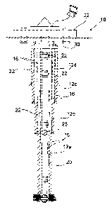
Figure 1 shows a well 10 comprising a series of casing strings 12a, 12b, 12c,
and 12d and adjacent annuli A,B,C,D between each casing string and the
CA 02805955 2013-01-18
WO 2012/010897
PCT/GB2011/051377
23
string inside thereof, with a drill string 20 provided inside the innermost
casing
12a.
As is conventional in the art, each casing strings extends further into the
well
than the adjacent casing string on the outside thereof. Moreover, the
lowermost portion of each casing string is cemented in place as it extends
below the outer adjacent string.
In accordance with one aspect of the present invention, safety packers 16 are
provided on the casing above the cemented as well as on the drill string 20.
These can be activated acoustically at any time including retroactively ie
after
the emergency, in order to block fluid flow through the respective annuli.
Whilst normal operation will not require the activation of such packers, they
will provide a barrier to uncontrolled hydrocarbon flow should the casing or
other portion of the well control fail.
Moreover sensors (not shown), in accordance with one aspect of the present
invention, are provided above and below said packers in order to monitor
downhole parameters at this point. This can provide information to operators
on any unusual parameters and the sealing integrity of the packer(s).
Acoustic relay stations 22 are provided on the drill pipe as well as various
points in the annuli to relay acoustic data retrieved from sensors in the
well.
A safety valve 25 is also provided in the drill string 20 and this can be
activated acoustically in order to prevent fluid flow through the drill
string.
CA 02805955 2013-01-18
WO 2012/010897
PCT/GB2011/051377
24
In such an instance a device (not shown) comprising a sonar receiver and an
acoustic transceiver installed or later landed at a wellhead apparatus such as
a BOP structure 30 at the top of the well. The operator sends a sonar signal
from a surface facility 32 which is converted to an acoustic signal and
transmitted into the well by the device. The subsea valve 25 picks up the
acoustic signal and shuts the well downhole (rather than at the surface), even
if other communications are entirely severed with the BOP.
In alternative embodiments a packer picks up the signal rather than the safety
valve 25. The packer can then shut a flowpath e.g. an annulus.
Thus embodiments of the present invention benefit in that they obviate the
sole reliance on seabed/rig floor/bridge BOP control mechanisms. As can be
observed by disastrous events in the Gulf of Mexico in 2010, the control of a
well where the BOP has failed can be extremely difficult and ensuing
environmental damage can occur given the uncontrolled leak of hydrocarbons
in the environment. Embodiments of the present invention provide a system
which reduce the risk of such disastrous events happening and also provide a
secondary control mechanism for controlling subsurface safety mechanisms,
such as subsurface valves, sleeves, plugs and/or packers.
For certain embodiments a control device is provided on a buoy or vessel
separate from a rig. The device comprises sonar transmitter and a satellite
receiver. The device can therefore receive a signal from a satellite directed
from an inland installation, and communicate this to the well in order to shut
down the well; all independent of the rig. In such embodiments, the well can
be safely closed down even in the disastrous event of losing the rig.
CA 02805955 2013-01-18
WO 2012/010897
PCT/GB2011/051377
A casing valve sub 400 is shown Figs. 4a ¨ 4c comprising an outer body 404
having a central bore 406 extending out of the body 404 at an inner side
through port 408 and an outer side through port 410. A moveable member in
the form of a piston 412 is provided in the bore 406 and can move to seal the
5 port 408. Similarly a second moveable member in the form of a piston 414
is
provided in the bore 406 and can move to seal the port 410. Actuators 416,
418 control the pistons 412, 414 respectively.
The casing valve sub 400 is run as part of an overall casing string, such as a
10 casing string 12 shown in Fig. 1, and positioned such that the port 408
faces
an inner annulus and the port 410 faces an outer annulus.
In use, the pistons 412, 414 can be moved to different positions, as shown in
Figs. 4a, 4b and 4c, by the actuators 416, 418 in response to wireless signals
15 which have been received. Thus the pressure between the inner and outer
annuli can be sealed from each other by providing at least one of the pistons
412, 414 over or between the respective ports, 408, 410 as shown in Fig. 4a,
4c.
20 In order to equalise the pressure between the inner and outer annuli,
the
pistons 412, 414 are moved to a position outside of the ports 408, 410 so
they do not block them nor block the bore 406 therebetween, as shown in Fig.
4b. The pressures can thus be equalised.
25 Thus such embodiments can be useful in that they provide an opportunity
to
equalise pressure between two adjacent casing annuli if one exceeded a safe
pressure and/or if an emergency situation had occurred.
CA 02805955 2013-01-18
WO 2012/010897
PCT/GB2011/051377
26
The port can then be isolated and pressure monitored to see if pressure is
going to build-up again. Thus, in contrast to for example a rupture disk,
where it cannot return to its original position, embodiments of the present
invention can equalise pressure between casing strings, be reset, and then
repeat this procedure again, and for certain embodiments, repeat the
procedure indefinitely.
In one scenario the pressure in a casing string may build up due to fluid flow
and thermal expansion. A known rupture disk can resolve problems of
excessive pressure, and the well can continue to function normally. However
a further occurrence of such excess pressure cannot be dealt with. Moreover
it is sometimes difficult to ascertain whether the excess pressure was caused
by such a manageable event or whether it is indicative of a more serious
problem especially if repeated occurrences of the excess pressure cannot be
detected nor alleviated in known systems. Embodiments of the present
invention mitigate these problems. For some embodiments, a number of
different casing subs 401 may be used in one string of casing.
Figure 2 shows a transmitting portion 250 of the safety mechanism. The
portion 250 comprises a transmitter (not shown) powered by a battery (not
shown), a transducer 240 and a thermometer (not shown). An analogue
pressure signal generated by the transducer 240 passes to an electronics
module 241 in which it is digitised and serially encoded for transmission by a
carrier frequency, suitably of 1Hz ¨ 10kHz, preferably lkHz ¨ 10kHz, utilising
an FSK modulation technique. The resulting bursts of carrier are applied to a
magnetostrictive transducer 242 comprising a coil formed around a core (not
shown) whose ends are rigidly fixed to the well bore casing (not shown) at
CA 02805955 2013-01-18
WO 2012/010897
PCT/GB2011/051377
27
spaced apart locations. The digitally coded data is thus transformed into a
longitudinal sonic wave.
The transmitter electronics module 241 in the present embodiment comprises
a signal conditioning circuit 244, a digitising and encoding circuit 245, and
a
current driver 246. The details of these circuits may be varied and other
suitable circuitry may be used. The transducer is connected to the current
driver 246 and formed round a core 247. Suitably, the core 247 is a
laminated rod of nickel of about 25 mm diameter. The length of the rod is
chosen to suit the desired sonic frequency.
Figure 3 shows a receiving portion 360 of the safety mechanism. A receiving
portion 361 comprises a filter 362 and a transducer 363 connected to an
electronics module powered by a battery (not shown). The filter 362 is a
mechanical band-pass filter tuned to the data carrier frequencies, and serves
to remove some of the acoustic noise which could otherwise swamp the
electronics. The transducer 363 is a piezoelectric element. The filter 362 and
transducer 363 are mechanically coupled in series, and the combination is
rigidly mounted at its ends to one of the elongated members, such as the
tubing or casing strings (not shown). Thus, the transducer 363 provides an
electrical output representative of the sonic data signal. Electronic filters
364
and 365 are also provided and the signal may be retransmitted or collated by
any suitable means 366, typically of a similar configuration to that shown in
Fig.2.
An advantage of certain embodiments is that the acoustic signals can travel
up and down different strings and can move from one string to another.
Thus linear travel of the signal is not required. Direct route devices thus
can
CA 02805955 2013-01-18
WO 2012/010897
PCT/GB2011/051377
28
be lost and a signal can still successfully be received indirectly. The signal
can also be combined with other wires and wireless communication systems
and does not have to travel the whole distance acoustically.
Improvements and modifications may be made without departing from the
scope of the invention. Whilst the specific example relates to a subsea well,
other embodiments may be used on platform or land based wells.