Note : Les descriptions sont présentées dans la langue officielle dans laquelle elles ont été soumises.
= = CA 02807619 2013-02-06
DEVICE AND METHOD FOR DETECTING, MONITORING AND/OR
CONTROLLING RACING VEHICLES
The present invention relates to a method and a device for the detection, mon-
itoring and/or controlling of racing vehicles on a racetrack, wherein a
respective rac-
ing vehicle is monitored with at least one camera when traversing a
predetermined
section of track, in particular the starting line and/or finishing line,
wherein the images
provided by the camera are recorded using a recording device.
Such control and monitoring devices are especially used with model race-
tracks, in particular so-called slot car tracks, but can in principle also be
used on real
racetracks and the racing vehicles that are driving on them. As racing
vehicles vari-
ous vehicle types, e.g. automobiles or motorcycles, naturally come into
consideration,
but in principal other race objects, such as for example horses, harness
racing car-
riages or waterborne vehicles such as racing boats can be equipped or
monitored
and detected with corresponding devices, so that the term racing vehicle is to
be
broadly interpreted in the context of the present application.
Racing on racetracks is usually monitored with the assistance of technical re-
cording means and controlled with corresponding control modules, which
concerns
e.g. the detection of the number of laps covered and/or the lap time or the
identifica-
tion of a respective vehicle or of a driver associated with said vehicle. In
addition to
the monitoring measures that have already been known for a long time, e.g.
light bar-
riers for the detection of speed, camera monitoring for the detection crossing
of the
finishing line or similar, in more recent times it has also been proposed to
monitor or
control vehicles and the drivers controlling them as well as the vehicle
position on the
racetrack and the time or distance travelled by electronic data transmission
from the
vehicle. For example, documents WO 2006/042235 A2 and US 2006/0183405 Al
propose fitting so-called RFID elements to the racing vehicles, i.e.
identification com-
ponents operating with radio data transmission, and to store in said RFID
elements a
vehicle identification, a driver identification and possibly other vehicle and
driver data
1
. . ' CA 02807619 2013-02-06
as well as race data, which are then read out by suitable RFID readers at the
race-
track, e.g. so that for each passage through the finishing line the RFID
element of a
vehicle is read out, the number of laps is correspondingly increased and is
stored
together with the vehicle identification and the driver identification.
Said document WO 2006/042235 A2 proposes, in addition to said RFID read-
ers, placing conductor loops or light projectors in the roadway in order to
detect vehi-
cles driving over them.
If cameras are used for the monitoring of a section of track, it is not easy
to
manage the resulting image flow and data flow during the recording and to
select an
image or the few images therefrom that are of interest and which actually show
the
respective event. For example, high-speed cameras are readily used for the
monitor-
ing of the starting process or the finish or another significant section of
track, such as,
for example, a split time line, a knoll or a steep curve, in order to be able
to show the
race event of interest in a time loop or to have an image available, which
actually
shows the racing vehicle just at the instant at which it is passing over the
section of
track of interest. For racing vehicles traveling at very high speed, with
cameras that
can only record a limited number of images per second it is clearly not
possible in
any way to shoot an image accurately at the time at which, for instance, the
front of a
vehicle is crossing the finishing line. On the down side, this means, however,
that a
plurality of images and data are produced that are not of interest. If said
images are
all recorded, a great deal of memory space is required and moreover the later
eval-
uation of the images is made difficult, because large numbers of images and
quanti-
ties of data have to be checked through or analyzed in order to select an
image or
the few images which actually show the event to be monitored.
A camera monitoring system for monitoring of the finish in track and field
events is known from DE 103 36 447 Al, in which the finishing of a runner
itself is
detected by means of a light barrier and images of the runner are recorded
using a
camera while crossing the finishing line. The race number of a respective
runner that
has crossed the finishing line is subsequently determined using image
recognition.
2
= CA 02807619 2013-02-06
Said monitoring system is, however, ultimately unsuitable for monitoring of
racing
vehicles or cannot cope with the associated race conditions, because as a
result of
the very much lower speed of runners when crossing the finishing line even
with rel-
atively few images per second an image is normally available that actually
shows the
crossing of the finishing line. Accordingly, processing can take place with
very many
fewer images to be stored. In order to reliably capture e.g. a crossing of the
finishing
line with an image for racing vehicles with very much higher speed, the
camera, e.g.
in the form of a high speed camera, must produce very many images per second,
so
that as a consequence a very much larger image and data flow is processed. The
system mentioned according to DE 103 36 447 Al is not capable of this.
Furthermore, US 4,183,056 describes an image recording system for monitor-
ing the impact of a tennis ball on or close to a boundary line, wherein the
boundary
line should be made pressure sensitive in order to detect the impact of the
ball and to
start the recording of the images permanently delivered by a camera. The
recording
is then stopped again after the expiry of a predetermined time interval. With
this sys-
tem, however, there is the problem that the recording interval is only set in
train with
the impact of the ball on the line itself, and thus no images can be recorded
or pro-
vided, which also show the sequences immediately prior to an interesting
event, i.e.
no images can be shown that show this ball shortly before its impact.
Furthermore, in
the event of a signal from the pressure sensitive boundary line, a marker is
supplied
in the associated camera image and recorded therewith, so that during a
subsequent
playback the marker can be seen in the image and the time of the ball's impact
can
be indicated exactly. For image analysis or evaluation such an associated
storage of
a corresponding marker is, however, only conditionally adequate, because large
quantities of data occur and relatively long search times arise for a
corresponding
image evaluation. In addition, said system is less suitable for monitoring
racing vehi-
cles, because for an automobile race or a motorcycle race those fractions of a
se-
cond after the crossing of the finishing line are of less interest, but those
fractions of a
3
CA 02807619 2013-02-06
second prior to crossing the finishing line are of greater interest and are
thus to be
stored.
On this basis the object of the present invention is to provide an improved de-
vice of the above-mentioned type, which avoids the disadvantages of the prior
art
and can be further developed in an advantageous manner. In particular,
automatic
camera monitoring of the traversing of a section of track of interest with
high accura-
cy is enabled, without having to store large numbers of images and quantities
of data
and without having to take into account tedious, complex evaluation processes.
According to the invention, said object is achieved with a device as claimed
in
claim 1 and a method as claimed in claim 12. Preferred embodiments of the
invention
are the subject of the dependent claims.
It is thus proposed to restrict the recording of the images provided by the
cam-
era to a defined time window, which is selected to be around the traversing of
the
section of track of interest or in proximity thereto, and thereby to detect
the actual
traversing of the section of track with a sensor device that is separate from
the cam-
era in order to be able to suitably mark the image acquired at the time of the
actual
traversing of the section of track, as long as it lies within said time
window. According
to the invention, a recording controller for the automatic recording of the
images pro-
vided by the camera only during a defined time window, within which a
traversing of
the section of track is to be determined, a sensor device for the detection of
the trav-
ersing of the section of track and a marking device for the marking of a
recorded im-
age depending on a sensor signal of the sensor device and its impact in the
deter-
mined time window are provided. On the one hand the quantity of data to be
stored
and evaluated is limited through the restriction of the image recording to a
limited
time window. On the other hand, through the generation of a marker for a
determined
image depending on a sensor signal, which indicates the traversing of the
section of
track of interest, and the storing of said marker in an event list
significantly simplifies
the locating of the final image of interest, because the image associated with
the re-
spective marker is only to be selected from the stored images, so that for the
repro-
4
CA 02807619 2013-02-06
duction of the race event of interest only the marked image and possibly some
imag-
es or image sequences, which have been recorded before and after the marked im-
age, have to be played back. Here the stored images themselves do not have to
be
searched for the presence of a marker, but only the event list in which the
respective
markers are deposited has to be gone through. Using a marker read out of the
mark-
er list, the image associated therewith can then be selected, which image then
dis-
plays the respective event such as e.g. the crossing of the finishing line.
The storage
of the markers separately from the associated images or the images combined
therewith in an event list significantly reduces the quantity of data to be
processed
during race evaluation and correspondingly reduces the access and evaluation
times.
Accordingly, for monitoring the racetrack a plurality of cameras and/or high
speed cameras can also be used, which produce a large flow of images without
the
storage and evaluation process being hindered thereby. On the other hand,
simple
monitoring of a correct race procedure can be achieved by the said marking
tech-
nique and its interaction with the recording in a defined time window, because
the
images recorded in the corresponding time window only have to be checked for
whether one of the images carries a corresponding marker. In other words, if
none of
the recorded images are provided with a marker, this leads to the conclusion
that a
corresponding event did not occur in the predetermined time window. In
particular,
this can be used for determining false starts or premature starts.
In a development of the invention the recording controller can determine the
time window, within which the images provided by the camera are recorded, in
differ-
ent ways. For this purpose the controller can comprise various determination
devices
for the determination of the start and end of the time window. In particular,
the con-
troller can comprise a determination device for the automatic determination of
the
start and end of the time window depending on a racing vehicle position and/or
a
race event.
In an advantageous development of the invention the recording controller can
determine said time window depending on a start signal and/or on a start
preparation
5
CA 02807619 2013-02-06
signal, wherein for the determination of the time window, e.g. the signals of
a starting
light can be taken into account. Advantageously, said determination device can
com-
prise detection means for the detection of a start preparation signal and/or a
start
signal as well as a timer or a timing controller for the output of an end
signal for the
time window after the expiry of a predetermined time interval following the
detection
of the start preparation signal and/or of the start signal. If e.g. a starting
light known
from Formula 1 is used, with which an increasing number of red lights is
initially illu-
minated for displaying the preparation for starting and then the start signal
is indicat-
ed by a green light, said time window can be opened with one of the red lights
and
closed again after the expiry of a predetermined time interval following
receipt of the
green light. If on the other hand, e.g. on a slot car track, the power supply
of the track
is only applied shortly before outputting the start signal, the time window
can be
opened or started for the recording of the camera images by said determination
de-
vice if corresponding voltage and/or current detection means detects the
application
of the electrical power to the power supply contacts of the slot car track.
In a development of the invention, the time window for the starting process is
hereby opened at a predetermined time interval before the actual start signal,
e.g. by
detection of the red light of a traffic light or the activation of the power
supply of the
slot car track, wherein advantageously said time window is closed again with
the out-
put of the start signal or just after the output of the start signal, so that
a normal trav-
ersing of the starting line following the output of the start signal is no
longer detected
at all or a marker is no longer applied to the recorded images. The quantities
of data
can thus be further reduced or a simple detection of a premature start is
enabled,
because during evaluation of the recorded images no marker is detected,
enabling a
proper starting process to be deduced. In particular, for this purpose said
time win-
dow for the recording of the camera images is closed again by the start signal
before
the expiry of a normal human reaction time interval. For example, said time
window
can be closed again a few fractions of a second after the output of the start
signal,
e.g. after 100 ms. Each conformant starting process having a human reaction
time
6
CA 02807619 2013-02-06
leads to an actual crossing of the starting line at a point in time that is
outside the
specified time window. Accordingly, the sensor device only outputs the signal
indicat-
ing the crossing after the end of the recording, so that no further recorded
image can
be marked by the marking device.
According to a further advantageous embodiment of the invention, said time
window can also be specified in a different manner, in particular for the
determination
of a crossing of the starting line or a split time recording, for which
purpose said re-
cording controller comprises a suitable differently designed determination
device for
the determination of the time window. In an advantageous development of the
inven-
tion, said determination device can comprise detection means for the detection
of the
approach of a racing vehicle to the predetermined section of track and
detection
means for the detection of the departure of the racing vehicle from the
predetermined
section of track and can specify said time window for the recording of the
camera
images depending on the signals of said detection means. Alternatively or
additional-
ly, the determination device could also comprise a timer or a timing sequence
control-
ler, which determines the end of the time window after the expiry of a
predetermined
time interval from detection of the approach of the racing vehicle to the
section of
track. If it is detected e.g. by said detection means for the detection of the
approach
that a racing vehicle has reached or traversed a predetermined section before
the
section of track of interest, it can be concluded therefrom that for normal
operation
the section of track of interest has been traversed within a predetermined
time inter-
val. However, a determination of the time window with the aid of both the
detection of
the approach and also the detection of the departure of the racing vehicle is
more
accurate and independent of speed, wherein said timer may nevertheless be able
to
be used in order to carry out a plausibility check on the detection of the
approach and
the detection of the departure of the racing vehicle towards or away from the
prede-
termined section of track.
In an advantageous development of the invention, the approach and the de-
parture of the racing vehicle towards or away from the section of track of
interest can
7
CA 02807619 2013-02-06
be detected by means of sensors disposed on the racetrack before and after
said
section of track. The sensor signal of the sensor disposed before the section
of track
indicates the approach of the racing vehicle, whereas the sensor disposed
after the
section of track of interest indicates the departure of the racing vehicle
from said sec-
tion of track. Said signals of the sensors can be used as a trigger signal for
starting
the recording or for ending the recording of the images provided by the
camera.
Said sensors can be of fundamentally different design here, wherein in an ad-
vantageous development of the invention inductive sensors are disposed before
or
after the section of track to be monitored in order to detect the approach or
the depar-
ture of the racing vehicle towards or away from said section of track. An
optical sen-
sor, e.g. in the form of a light barrier, can also be used alternatively or
additionally to
such an inductive sensor. In order to be able to detect not only the approach
or the
departure of a racing vehicle as such, but also moreover to be able to record
contin-
uous information, intelligent sensors can also be used, in particular in the
form of an
RFID reader and/or of a barcode reader, so that not only the approach or the
depar-
ture of a racing vehicle can be detected, but which racing vehicle is
approaching or
departing can also still be detected by reading an RFID element or barcode
element
attached to the vehicle.
Similarly to said sensors for the determination of the time window for the re-
cording of the camera images, the sensor device for the determination of the
actual
traversing of the section of track to be monitored can also be of a different
design.
Advantageously, said sensor device for the detection of the traversing of the
section
of track to be monitored can comprise an optical sensor, preferably in the
form of a
light barrier, which can very precisely detect the exact point in time of the
traversing
and can provide the corresponding sensor signal sufficiently rapidly.
Alternatively or
additionally, said sensor device can, however, also comprise other sensors,
such as
e.g. inductive sensors or even said RFID reader or barcode reader, in order to
also
detect the vehicle identity. But in order to be able to measure the passage of
the rac-
ing vehicle with adequate precision and to provide the sensor signal suitably
rapidly,
8
CA 02807619 2013-02-06
said optical Sensor in the form of a light barrier is especially advantageous.
Said fur-
ther sensors, e.g. RFID readers or barcode readers, can advantageously be addi-
tionally provided in order to be able to determine the vehicle identity.
In an advantageous development of the invention, said sensor devices for the
detection of the approach and departure of the racing vehicles and the
detection of
the exact traversing of the section of track of interest can be integrated
into the road-
way and/or disposed under the roadway. In order to ensure simple mounting
here,
said sensor devices can be mounted on a common sensor support, which can pref-
erably be laterally inserted from the edge of the roadway into an
accommodation
space under the roadway.
In order to be able to restrict a subsequent playback of the recorded images
to
the actual images of interest, in a development of the invention a playback
controller
for the automatic playback of recorded images can be provided, which comprises
a
marker reader, which reads or detects the markers attached to the images. By
means
of suitable selection means the playback controller can then select those
stored im-
ages that have a marker, wherein image sequences stored shortly before and
after a
marked image can optionally be selected therewith and displayed.
Advantageously,
the playback controller can control the playback of the recorded images
depending
on the markers read out, in particular in such a way that image sequences
selected
for the playback can then be slowed or stopped in the manner of a slow motion
rep-
resentation, if a marked image is being played back. Alternatively or
additionally, a
rewind and a repeated playback of the corresponding image sequence can also be
carried out if a marked image is being played back, e.g. in order to show the
crossing
of the finishing line a second time.
The invention is explained in detail below using a preferred example embodi-
ment and associated drawings. The drawings show:
Fig. 1: a schematic illustration of the monitoring device for monitoring the
rac-
ing vehicles on a racetrack according to an advantageous embodiment of the
inven-
tion, which shows the cooperation of a camera for the monitoring of the
crossing of
9
= CA 02807619 2013-02-06
the starting line and the crossing of the finishing line and the control
elements for
controlling the recording of the camera images and the repeated playback of
the rec-
orded images,
Fig. 2: a timing diagram for illustration of the time window in which images
from the camera of the system of Fig. 1 are recorded and the trigger signals,
on
whose occurrence individual images are marked, and
Fig. 3: a schematic illustration of a multi-track racetrack, its monitoring by
means of a plurality of cameras and the connection of the monitoring device
from Fig.
1.
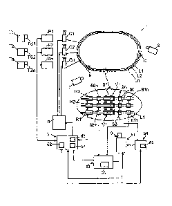
The racetrack 1 shown in Fig. 3 comprises a plurality of lane tracks L1, L2,
Ln
and can advantageously be in the form of a so-called slot car track, on which
racing
vehicles V1, V2, Vn having current pickups run in tracks, which tracks are let
into the
roadway of the racetrack 1. In a conventional manner, power supply lines are
set into
said lane tracks (not shown in detail), whose current or voltage application
can be
controlled by a controller C1, C2, Cn connected therewith, wherein the current
or
voltage supply of each lane track L1, L2, Ln can be controlled or regulated
inde-
pendently of the other lane tracks.
As Fig. 3 shows, the racetrack 1 in the illustrated embodiment has two associ-
ated cameras 7 and 8, which monitor various sections of the racetrack 1 in
order to
be able to transmit each race in the form of television images, as will be
explained.
Advantageously, competitors can be registered for the racetrack 1 with the aid
of a central computer 3. The race can be carried out in various versions, e.g.
it can
be an objective to determine the fastest driver in each case, i.e. that driver
who has
controlled a racing vehicle controlled by him along a defined section of track
of the
automobile racetrack in first place. Alternatively or additionally, the number
of laps
achieved over a predetermined time can determine the result of the race.
Each competitor Ti, T2, Tn is first allocated a competitor memory TS1, TS2,
TSn, preferably in the form of an RFID card with a respective driver identity
TID1,
TID2, TIDn, wherein before the race the registration of each competitor takes
place
10
CA 02807619 2013-02-06
by a suitable receiver and/or reader, e.g. in the form of an RFID reader,
reading the
respective competitor memory TS1, TS2, TSn, wherein the respective allocated
driv-
er identity TID is determined and is stored in a first memory area of a
central data-
base.
Furthermore, the racing vehicles V1, V2, Vn are provided with a respective
vehicle memory Si, S2, Sn, preferably in the form of an RFID element, which is
allo-
cated a respective vehicle identity. In a further step, likewise before the
running of the
race, registration of the vehicle identities is carried out by reading out of
the vehicle
memory Si, S2, Sn by means of a suitable receiver or reader, wherein the
vehicle
identities are determined and transferred to said database, where they are
deposited
in a second memory area.
Following successful registration of the racing vehicles V1, V2, Vn and the
competitors Ti, T2, Tn, the central computer 3 automatically performs the
allocation
of the competitors to the racing vehicles before the start of the race and
displays this
allocation on a display. For this the computer 3 can comprise a random number
gen-
erator, which carries out the allocation of the competitors to the racing
vehicles on a
random basis.
Advantageously, the computer 3 also automatically carries out an allocation of
the racing vehicles to the respective lane tracks, wherein advantageously said
alloca-
tion to the lane tracks can also be carried out on a random basis from the
random
number generator. Said allocation is also displayed on the display before the
start of
the race.
According to the predetermined allocation and selection, the racing vehicles
V1, V2, Vn are then to be placed on the corresponding lane tracks L1, L2, Ln
of the
racetrack 1. The correct placement of the racing vehicles is monitored by
means of
the respective vehicle memories provided on the vehicles, wherein
advantageously
the respective lane tracks L1, L2, Ln have associated receivers/readers R1,
R2, Rn,
e.g. these are set therein or attached thereto, in order to read out the
vehicle memory
Si, S2, Sn of the vehicle that is located on the respective lane track. Said
receiv-
1 1
= = CA 02807619 2013-02-06
ers/readers R1, R2, Rn monitor the vehicle identity and forward the same to an
acti-
vation device, which can be disposed in the computer 3 or said controllers Cl,
C2,
Cn. If the correct vehicle is on the correct lane track, the corresponding
lane track
and the corresponding vehicle are activated.
Furthermore, at the controllers Cl, C2, Cn, the competitor memory TS1, TS2,
TSn of the competitors being handled by the respective controller Cl, C2, On
is read
out by means of receivers/readers P1, P2, Pn provided there. This can e.g. be
car-
ried out in such a way that the respective competitor inserts his RFID card
into the
corresponding controller P1, P2, Pn or places it in contactless communication.
The
read out competitor identities TID1, TID2, TIDn are then likewise sent to said
activa-
tion device in order to be compared there with the allocation predetermined by
the
computer 3. If the correct competitor is on the correct controller, the
respective con-
troller is activated.
If all competitors are on the predetermined controllers Cl, C2, Cn and all rac-
ing vehicles V1, V2, Vn are on the correct lane tracks, the computer 3 can
generate a
corresponding start signal, which is displayed in a suitable manner.
Figures 1 and 2 show the device for controlling the camera 7 of Fig. 3 and for
recording and reselection of the corresponding images in detail.
At the start said computer 3 first generates a start preparation signal, e.g.
by a
traffic light being switched to red and/or by the power supply of the
racetrack 1 being
activated. The computer 3 sends said start preparation signal to a recording
control-
ler 52, which controls the recording point in time of the camera 7. On
detection of the
start preparation signal, said camera 7 is activated or the images provided
thereby
are recorded in a recording device 51, which can be integrated into the
camera.
The computer 3 then gives the actual start signal, e.g. by switching a traffic
light indicator to green light. Said signal is in turn processed by said
recording con-
troller 52, namely so that the time window for recording the camera images
previous-
ly opened with the start preparation signal is closed. This can advantageously
take
place with an offset in time, wherein the time offset can be specified by a
timer 57.
12
= CA 02807619 2013-02-06
For example, a delay time of approx. 100 ms from the start signal can be
provided. In
this way, any premature start would be reliably recorded in the recording
device 51,
whereas on the other hand no unnecessary images are stored if all vehicles
start
normally.
The actual crossing of the starting line 50 is detected by a sensor device 53,
which e.g. can comprise a sensor 30 provided at the starting line 50, which
e.g. can
be in the form of an optical sensor and/or of a light barrier. For example, a
photo
sensor can be disposed in an accommodation space under the roadway, which
photo
sensor monitors the crossing of the starting line 50 through a transparent
sensor win-
dow in the roadway, wherein said photo sensor 30 operates as a photoresistor
or as
a photodiode or even as a phototransistor, which operates by utilizing the
internal
photoelectric effect, or can even be in the form of a photocell or
photomultiplier or of
a pyroelectric sensor, which operates by utilizing charge displacements
resulting from
the temperature change in the event of light absorption.
During crossing of the starting line 50, said sensor device 53 provides a
corre-
sponding sensor signal, which is used by a marking device 54 to mark the image
recorded at the corresponding moment. If said image lies outside the
previously de-
scribed time window, however, no marking takes place, i.e. in the event of a
normal
start none of the images are marked. Fig. 2 also shows said course of the
image re-
cording and the trigger signals from the sensor device 53, in which the time
window
ZFstart corresponding to the premature start phase, during which the camera
images
are recorded, is shown on timeline A. The sensor signals SS Start lie in time
just after
said time window, so that no marking takes place. In said Fig. 2, partial view
B shows
the corresponding sensor or trigger signal, whereas partial view C then shows
the
complete information.
When crossing the finishing line the time window ZFFimsh is determined by the
determination device 55 with the aid of detection means 58 and 59, which
indicate
the approach of the racing vehicles to the finishing line 50 as well as the
departure
from the finishing line following the crossing. As Fig. 1 shows, sensors 60
and 61 are
13
CA 02807619 2013-02-06
disposed for this purpose on the racetrack 1 a short distance before the
finishing line
50 and a short distance after the finishing line, in particular under the
surface of the
roadway, wherein said sensors can be in the form e.g. of inductive sensors. If
the
first racing vehicle passes over the approach sensor 60, this provides a
signal which
is used by the recording controller 52 to activate the camera 7 or the
recording device
51. If the last racing vehicle then travels across the finishing line and the
departure
sensor 61 after the finishing line 50, the corresponding sensor signal is used
by the
recording controller 52 to close the time window for the recording and to end
the re-
cording.
During said time window ZFFinish for the crossing of the finishing line
specified
by means of the determination device 55, sensor signals SS Finish are then
provided
by the previously mentioned light barrier sensor 30 if the racing vehicles are
actually
traveling across the finishing line 50. Said trigger signals are illustrated
in Fig. 2 on
timeline B and on timeline C and indicate in the example embodiment shown the
crossing of the finishing line by the first racing vehicle and the second
racing vehicle.
The images "3924" and "4060" recorded at the corresponding points in time
are provided with a marker by said marking device 54.
The repeated playback of the recorded images is controlled by the control
computer 3. Said computer 3 registers the crossings of the finishing line by
means of
a time measurement unit 65, which is connected to said finishing line crossing
sen-
sors 30. If the automobiles are at the finish, the camera 7 or the recording
device 51
is interrogated by the computer 3 regarding the occurring events. Said query
provides
the event list shown against time as illustrated in Fig. 2, partial view C.
The control
computer 3 can then play back the requested images, wherein the markers, read
by
a marker reader 63, on the images can be used by the playback controller 62
during
playback, e.g. just during the crossing of the finishing line by a vehicle to
stop or to
delay or to reverse the image sequence and to play it back again.
14