Sélection de la langue

Search

Sommaire du brevet 2807911 

Énoncé de désistement de responsabilité concernant l'information provenant de tiers

Une partie des informations de ce site Web a été fournie par des sources externes. Le gouvernement du Canada n'assume aucune responsabilité concernant la précision, l'actualité ou la fiabilité des informations fournies par les sources externes. Les utilisateurs qui désirent employer cette information devraient consulter directement la source des informations. Le contenu fourni par les sources externes n'est pas assujetti aux exigences sur les langues officielles, la protection des renseignements personnels et l'accessibilité.

Disponibilité de l'Abrégé et des Revendications

L'apparition de différences dans le texte et l'image des Revendications et de l'Abrégé dépend du moment auquel le document est publié. Les textes des Revendications et de l'Abrégé sont affichés :

  • lorsque la demande peut être examinée par le public;
  • lorsque le brevet est émis (délivrance).
(12) Demande de brevet: (11) CA 2807911
(54) Titre français: ARRANGEMENT DE CONSTRUCTION DE SYSTEME DE TURBINE EOLIENNE
(54) Titre anglais: WIND TURBINE SYSTEM CONSTRUCTIVE ARRANGEMENT
Statut: Réputée abandonnée et au-delà du délai pour le rétablissement - en attente de la réponse à l’avis de communication rejetée
Données bibliographiques
(51) Classification internationale des brevets (CIB):
  • F03D 3/04 (2006.01)
  • F03D 3/02 (2006.01)
(72) Inventeurs :
  • MURATA, AKITOSHI (Brésil)
(73) Titulaires :
  • AKITOSHI MURATA
(71) Demandeurs :
  • AKITOSHI MURATA (Brésil)
(74) Agent: SMART & BIGGAR LP
(74) Co-agent:
(45) Délivré:
(22) Date de dépôt: 2013-03-01
(41) Mise à la disponibilité du public: 2013-09-06
Licence disponible: S.O.
Cédé au domaine public: S.O.
(25) Langue des documents déposés: Anglais

Traité de coopération en matière de brevets (PCT): Non

(30) Données de priorité de la demande:
Numéro de la demande Pays / territoire Date
1020120050188 (Brésil) 2012-03-06

Abrégés

Abrégé anglais


This patent refers to a system constructed by the wind turbine (1),
placing two protectors; the first protector is placed on the opposite side of
the
wind direction to externally protect the wind turbine (1), called fixed
protector
(2), to divert the wind in the opposite rotary direction of wind turbine (1);
the
second protector is place in the intermediate area of the wind turbine (1),
between the fixed protector (2) and located on the same side of the fixed
protector (2), called mobile protector (3). Depending on the exit angle on the
side of same wind direction and wind turbine rotation (1), this exit angle is
controlled to contain the wind turbine rotation (1). This system may be
installed
upright, double or single, and horizontally, multiple.

Revendications

Note : Les revendications sont présentées dans la langue officielle dans laquelle elles ont été soumises.


5
CLAIM
CONSTRUCTIVE ARRANGEMENT IN A SYSTEM OF WIND TURBINE
characterized for being constructed by wind turbine (1), placing two
protectors;
the first protector is placed at the side that is against the direction of the
wind to
protect externally the wind turbine (1), named fixed protector (2), to divert
the
wind in opposite rotary direction of the wind turbine (1), in order not to
impair the
rotating strength and prevent noise emission; The second protector is placed
in
the intermediate area of the wind turbine (1), between the fixed protector (2)
and located on the same side of the fixed protector (2), called mobile
protector
(3). Depending on the exit angle on the side of same wind direction and wind
turbine rotation (1), this exit angle is controlled with the rotation servo
controller
(4), depending on the establishment of rotation in the wind turbine (1). This
system may be installed upright, double or single, and horizontally, multiple.

Description

Note : Les descriptions sont présentées dans la langue officielle dans laquelle elles ont été soumises.

CA 02807911 2013-03-01
WIND TURBINE SYSTEM CONSTRUCTIVE ARRANGEMENT
This patent refers to a wind turbine system constructive arrangement.
This new system proves to be more effective than the current system on the
market. The current model uses the same style of aircraft propeller; this
current
wind generator system needs to create pressure difference to achieve rotary
force; when the wind moves the propeller, the upper part creates high
pressure,
while the lower part creates low pressure. By using this pressure difference,
it
does not take full advantage of the wind force, and generates noise by wind
friction on propeller.
Now, a patent for the invention that solves the problem is requested. The
solution consists in providing the wind turbine with two protectors: the first
protector is to be placed on the opposite side to the wind direction, in order
to
protect the wind turbine externally (1), called fixed protector (2), to divert
all the
wind in the opposite rotary direction of wind turbine (1), in order not to
impair the
rotating strength and prevent noise emission. The second protector is placed
in
the intermediate area of the wind turbine (1) between the fixed protector (2)
and
located on the same side of the fixed protector (2), called mobile protector
(3)
depending on the exit angle on the side of same wind direction and wind
turbine
rotation (1), this exit angle is controlled with the rotation servo controller
(4),
which will establish the wind turbine rotational speed (1) and will protect it
from
strong winds. This system harnesses the power of direct wind, which will take
it
to the wind turbine (1) without friction and against the wind direction, so as
to
produce power in more efficient and quieter manner. This system may be
installed upright, double or single, and horizontally, multiple.
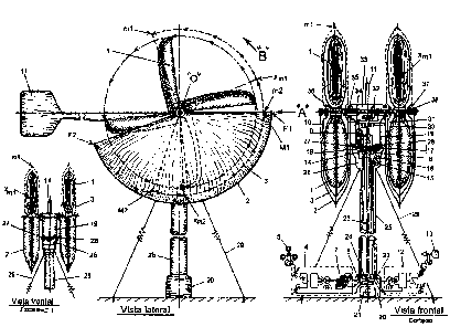
To a better composition of the aforementioned, of invention related to this
patent application is represented in:
Fig. 01 ¨ Double Vertical System
Figure 02 - Multiple Horizontal System
As seen in the figures attached hereto, the wind turbine system (1) may
use a vertical double system as in Fig. 01 or a multiple horizontal system as
in
Fig 02. These have the same functionality and effectiveness, and the use of
tall
towers and long propellers is not required. A more powerful wind generator and
a lower tower can be used and, therefore, different sizes of wind generator
may
be used closer to the floor, resulting in greater ease of access for storage
and/or maintenance. The double vertical system may also produce double wind
power with balanced weight. The multiple horizontal system may produce
multiplied wind power. Another advantage is the ability to attach fastening
cables to the end of the tower, becoming more firm and steady during strong
winds, which would make it safer.

CA 02807911 2013-03-01
2
The location of the two protectors, fixed and mobile, are according to the
figures: First figure establishes the direction of the wind "A" and the wind
turbine
(1) rotation direction, in direction "B" the fixed protector (2) needs to
protect the
wind turbine (1) externally on the counter direction side of the wind in the
area
(F1-"0"-F2), the mobile protector (3) must be on the same side of the fixed
protector (2) in the intermediate distance of the wind turbine (1), between
the
fixed protector(2) in the area (M1-"0"-M2), and the mobile protector (3). The
wind turbine (1) speed control is achieved through the servo speed controller
(4)
with wind speed meter (5) and wind turbine rotation meter (6); depending on
the
need established, the rotation servo controller (4) activates the servo motor
with
hydraulic transformer (7); this hydraulic flow passes through the rotating
hydraulic connection (8) and the hydraulic actuator is activated (9); by means
of
the actuating lever (10), this actuator controls the mobile protector (3)
placed in
position in figure (XM1-"o" XM2). When there are strong winds, the system
automatically will move to position (m1-"o"-m2) in order to protect the total
useful area with better security. This figure indicates the servo motor with
hydraulic transformer (7) with hydraulic actuator (9), but the mechanism can
be
provided with servo motor with actuator mechanism. In this case, it will be
necessary to change the rotary hydraulic connection (8) for a rotary
electrical
connection, but with same functionality.
Control in wind direction is also required and the fixed protector (2) must
always be on the wind counter direction side through the wind direction guide
(11). When the wind is low, guiding the wind direction guide (11) will be
hardly
achieved, so support from the wind direction controller servo (12) is required
with the wind direction meter (13) and the wind turbine direction meter (14).
Depending on the requirements set in the wind direction servo controller (12),
it
is achieved the automatic adjustment, by the servo motor mechanism (15), of
the electromechanical coupling (16), the smaller gear (17), and the larger
gear
(18). The larger gear is fixed on the outside of the hydraulic rotary
connection
(8) and is also attached to the center of the tower swivel space base (19),
which, in turn, is fixed to the wind direction guide (11), which is also fixed
to the
tower swivel space (19). This system has another advantage, when the servo
motor (15) is stopped, the electromechanical coupling (16) separates the servo
motor (15) with the smaller gear (17). Thus, the wind direction guide (11)
works
better, separating the larger load. This system is necessary because there are
weak winds before strong winds. In this moment, this wind direction servo
controller mechanism (12) directs the wind direction correctly, providing
better
security.
The best location to install servo controllers is the space at the tower
base (20), also installing the wind generator (21). The shaft of this
generator is
connected to the output of the gearbox (22) to increase the rotation of the
wind
turbine (1) and this shaft holds the roller bearing with axial bearing (24) to

CA 02807911 2013-03-01
3
secure and support the weight of the main shaft (23 ) within the tower base
space (20) and then driving the turret (25) with servo motor wires (15), the
electromechanical coupling wires (16), the wind turbine direction meter wires
(14) and the hydraulic transformer motor servo outlet pipes (7), through the
rotating hydraulic connection (8) to connect the hydraulic actuator (9) and to
direct the position of the mobile protector (3) through the actuating lever
(10).
These wires and pipes shall be fixed to the side of the tower (25) as to not
hinder the movement of the main shaft (23).
At the end of the tower, opening the fixed space of the tower (26) inside,
there is the servo motor (15), the electromechanical coupling (16) in the
center
of the ceiling of this fixed space of the tower (26), fixing part of the
hydraulic
rotary connection (8) to pass the hydraulic flow into the hydraulic actuator
(9). At
the center of that rotating hydraulic connection (8) there is the main shaft
(23),
other part of the hydraulic rotating connection (8) on the outside, with
larger
gear (18) installed in the center of the base of the tower swivel space (19).
After
fixing the larger gear, it will be required to install other stabilization
rotary
connection (27). This stabilization rotary connection uses bearings to keep
centered and the support of the weight on the rotary part with axial bearings.
The other part of this stabilization rotary connection is installed on the
corner of
the tower fixed space ceiling (26). In the corner of the base, within the
tower
swivel space (19), it is fixed together part of the fixing arms (28). The
other side
of the fixing arms is installed to the side of the fixed protector (2). On the
base
of this fixed space of the tower (26) it is fixed with fixing cables (29) to
help
stabilize and make tower (25) steady. In case of strong winds, there will be
greater security.
The main shaft (23) is fixed in the upper area of the tower swivel space
(19), with roller bearing (30), the reinforcement plate (31), to stabilize the
main
shaft (23). Then, the bevel gear (32) is connected to change the direction of
the
main shaft rotation (23) from vertical to horizontal; through the bevel gear,
horizontal shaft (33) is inserted; this horizontal shaft passes through the
rotary
bushing with bearing (34), this rotary bushing with bearing fixes, on one
side,
the actuating lever (10), for connecting the hydraulic actuator (9) and
connecting the other side of the actuating lever, but this rotary bushing with
bearing on the other hand is fixed to the mobile protector (3); above this
rotary
bushing with bearing there is another rotary bushing with bearing (35); this
bushing is fixed with the fixed protector (2) and upper portion of the tower
swivel
space (19) in two equal sides; the horizontal shaft (33) passes through the
bushing (36) and this bushing is securely fastened together with the
horizontal
axis and the wind turbine (1); the horizontal shaft runs through the rotary
bushing with bearing (37 ), fixing other side of the mobile protector (3); the
horizontal shafts runs through the rotary bushing with bearing (38), fixing
the
other side of the fixed protector (2).

CA 02807911 2013-03-01
4
The operation in Fig. 02 is the same as in Fig. 01, therefore, the same
items are used in both drawings. In Fig. 02, however, there is no need for
fixing
arms (28), roller bearing (30), reinforcement plate (31), bevel gear (32) and
horizontal shaft (33) using the main shaft (23) to the end.
The position of the wind turbine (1) and the hydraulic actuator (9), also in
Fig. 01, is vertical, and the quantity of wind turbine is double, but can be
single.
In this case, it is required to increase two more bevel gears. In Fig. 02, it
is
horizontal and the number of wind turbines is multiple, only defining the wind
generator capacity, the environment, and functionality space.

Dessin représentatif
Une figure unique qui représente un dessin illustrant l'invention.
États administratifs

2024-08-01 : Dans le cadre de la transition vers les Brevets de nouvelle génération (BNG), la base de données sur les brevets canadiens (BDBC) contient désormais un Historique d'événement plus détaillé, qui reproduit le Journal des événements de notre nouvelle solution interne.

Veuillez noter que les événements débutant par « Inactive : » se réfèrent à des événements qui ne sont plus utilisés dans notre nouvelle solution interne.

Pour une meilleure compréhension de l'état de la demande ou brevet qui figure sur cette page, la rubrique Mise en garde , et les descriptions de Brevet , Historique d'événement , Taxes périodiques et Historique des paiements devraient être consultées.

Historique d'événement

Description Date
Le délai pour l'annulation est expiré 2019-03-01
Demande non rétablie avant l'échéance 2019-03-01
Réputée abandonnée - omission de répondre à un avis sur les taxes pour le maintien en état 2018-03-01
Inactive : Abandon.-RE+surtaxe impayées-Corr envoyée 2018-03-01
Requête pour le changement d'adresse ou de mode de correspondance reçue 2018-01-12
Exigences relatives à la révocation de la nomination d'un agent - jugée conforme 2016-02-12
Inactive : Lettre officielle 2016-02-12
Exigences relatives à la nomination d'un agent - jugée conforme 2016-02-12
Demande visant la révocation de la nomination d'un agent 2016-01-29
Demande visant la nomination d'un agent 2016-01-29
Inactive : Page couverture publiée 2013-09-16
Demande publiée (accessible au public) 2013-09-06
Inactive : CIB attribuée 2013-06-14
Inactive : CIB en 1re position 2013-06-14
Inactive : CIB attribuée 2013-06-14
Inactive : Certificat de dépôt - Sans RE (Anglais) 2013-03-14
Exigences de dépôt - jugé conforme 2013-03-14
Demande reçue - nationale ordinaire 2013-03-14

Historique d'abandonnement

Date d'abandonnement Raison Date de rétablissement
2018-03-01

Taxes périodiques

Le dernier paiement a été reçu le 2017-02-21

Avis : Si le paiement en totalité n'a pas été reçu au plus tard à la date indiquée, une taxe supplémentaire peut être imposée, soit une des taxes suivantes :

  • taxe de rétablissement ;
  • taxe pour paiement en souffrance ; ou
  • taxe additionnelle pour le renversement d'une péremption réputée.

Veuillez vous référer à la page web des taxes sur les brevets de l'OPIC pour voir tous les montants actuels des taxes.

Historique des taxes

Type de taxes Anniversaire Échéance Date payée
Taxe pour le dépôt - générale 2013-03-01
TM (demande, 2e anniv.) - générale 02 2015-03-02 2015-02-19
TM (demande, 3e anniv.) - générale 03 2016-03-01 2016-02-18
TM (demande, 4e anniv.) - générale 04 2017-03-01 2017-02-21
Titulaires au dossier

Les titulaires actuels et antérieures au dossier sont affichés en ordre alphabétique.

Titulaires actuels au dossier
AKITOSHI MURATA
Titulaires antérieures au dossier
S.O.
Les propriétaires antérieurs qui ne figurent pas dans la liste des « Propriétaires au dossier » apparaîtront dans d'autres documents au dossier.
Documents

Pour visionner les fichiers sélectionnés, entrer le code reCAPTCHA :


Pour visualiser une image, cliquer sur un lien dans la colonne description du document. Pour télécharger l'image (les images), cliquer l'une ou plusieurs cases à cocher dans la première colonne et ensuite cliquer sur le bouton "Télécharger sélection en format PDF (archive Zip)" ou le bouton "Télécharger sélection (en un fichier PDF fusionné)".

Liste des documents de brevet publiés et non publiés sur la BDBC .

Si vous avez des difficultés à accéder au contenu, veuillez communiquer avec le Centre de services à la clientèle au 1-866-997-1936, ou envoyer un courriel au Centre de service à la clientèle de l'OPIC.


Description du
Document 
Date
(aaaa-mm-jj) 
Nombre de pages   Taille de l'image (Ko) 
Page couverture 2013-09-16 1 69
Description 2013-03-01 4 211
Dessins 2013-03-01 2 103
Revendications 2013-03-01 1 21
Abrégé 2013-03-01 1 17
Dessin représentatif 2013-08-09 1 38
Certificat de dépôt (anglais) 2013-03-14 1 157
Rappel de taxe de maintien due 2014-11-04 1 111
Courtoisie - Lettre d'abandon (requête d'examen) 2018-04-12 1 166
Courtoisie - Lettre d'abandon (taxe de maintien en état) 2018-04-12 1 174
Rappel - requête d'examen 2017-11-02 1 118
Taxes 2015-02-19 1 25
Changement de nomination d'agent 2016-01-29 2 131
Courtoisie - Lettre du bureau 2016-02-12 1 24
Courtoisie - Lettre du bureau 2016-02-12 1 22