Note : Les descriptions sont présentées dans la langue officielle dans laquelle elles ont été soumises.
CA 02808620 2014-12-08
HYDRODESULFURIZATION PROCESS WITH SELECTED LIQUID
RECYCLE TO REDUCE FORMATION OF RECOMBINANT
MERCAPTANS
FIELD OF THE DISCLOSURE
[0001] Embodiments disclosed here generally relate to processes for the
hydrodesulfurization of FCC naphtha. More particularly, embodiments disclosed
herein relate to processes for the hydrodesulfurization of FCC naphtha to
produce
gasoline fractions having low or undetectable mercaptan content.
BACKGROUND OF THE DISCLOSURE
[0002] Petroleum distillate streams contain a variety of organic chemical
components.
Generally the streams are defined by their boiling ranges, which determine the
composition. The processing of the streams also affects the composition. For
instance, products from either catalytic cracking or thermal cracking
processes
contain high concentrations of olefinic materials as well as saturated
(alkanes)
materials and polyunsaturated materials (diolefins). Additionally, these
components
may be any of the various isomers of the compounds.
[0003] The composition of untreated naphtha as it comes from the crude
still, or
straight run naphtha, is primarily influenced by the crude source. Naphthas
from
paraffinic crude sources have more saturated straight chain or cyclic
compounds. As
a general rule most of the "sweet" (low sulfur) crudes and naphthas are
paraffinic.
The naphthenic crudes contain more unsaturates, cyclic, and polycyclic
compounds.
The higher sulfur content crudes tend to be naphthenic. Treatment of the
different
straight run naphthas may be slightly different depending, upon their
composition due
to crude source.
[0004] Reformed naphtha or reformate generally requires no further
treatment except
perhaps distillation or solvent extraction for valuable aromatic product
removal.
Reformed naphthas have essentially no sulfur contaminants due to the severity
of their
pretreatment for the process and the process itself.
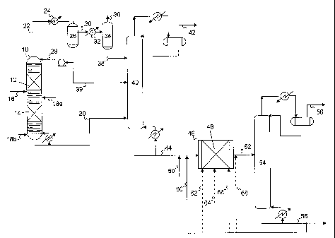
[0005] Cracked naphtha, as it comes from the catalytic cracker, has a
relatively high
octane number as a result of the olefinic and aromatic compounds contained
therein.
1
CA 02808620 2013-02-15
WO 2012/027007 PCT/US2011/039431
In some cases, this fraction may contribute as much as half of the gasoline in
the
refinery pool together with a significant portion of the octane.
[0006]
Catalytically cracked naphtha gasoline boiling range material currently forms
a significant part (-1/3) of the gasoline product pool in the United States
and is the
cause of the majority of the sulfur found in gasoline. These sulfur impurities
may
require removal in order to comply with product specifications or to ensure
compliance with environmental regulations, which may be as low as 10, 20 or 50
wppm, depending upon the jurisdiction.
[0007] The
most common method of removal of the sulfur compounds is by
hydrodesulfurization (HDS) in which the petroleum distillate is passed over a
solid
particulate catalyst comprising a hydrogenation metal supported on an alumina
base.
Additionally, large amounts of hydrogen are included in the feed. The
hydrodesulfurization reaction results in the production of hydrogen sulfide
according
to the following reaction: RSH + H2 <--> R' + H2S. Typical operating
conditions
for standard single pass fixed bed HDS reactors, such as in a trickle bed
reactor, are
temperatures ranging from 600 F to 780 F, pressures ranging from 300 to 3000
psig,
hydrogen recycle rates ranging from 500 to 3000 scf/bbl, and fresh hydrogen
makeup
ranging from 100 to 1000 scf/bbl.
[0008]
After the hydrotreating is complete, the product may be fractionated or simply
flashed to release the hydrogen sulfide and collect the desulfurized naphtha.
In
addition to supplying high octane blending components the cracked naphthas are
often used as sources of olefins in other processes such as etherifications,
oligomerizations, and alkylations. The conditions used to hydrotreat the
naphtha
fraction to remove sulfur will also saturate some of the olefinic compounds in
the
fraction, reducing the octane and causing a loss of source olefins. The loss
of olefins
by incidental hydrogenation is detrimental, reducing the octane rating of the
naphtha
and reducing the pool of olefins for other uses.
[0009]
Various proposals have been made for removing sulfur while retaining the
more desirable olefins. Because the olefins in the cracked naphtha are mainly
in the
low boiling fraction of these naphthas and the sulfur containing impurities
tend to be
concentrated in the high boiling fraction, the most common solution has been
prefractionation prior to hydrotreating. The prefractionation produces a light
boiling
2
CA 02808620 2013-02-15
WO 2012/027007 PCT/US2011/039431
range naphtha which boils in the range of Cs to about 150 F and a heavy
boiling range
naphtha which boils in the range of from about 150-475 F.
[0010] The
predominant light or lower boiling sulfur compounds are mercaptans
while the heavier or higher boiling compounds are thiophenes and other
heterocyclic
compounds. The separation by fractionation alone will not remove the
mercaptans.
However, in the past the mercaptans have been removed by oxidative processes
involving caustic washing. A combination of oxidative removal of the
mercaptans
followed by fractionation and hydrotreating of the heavier fraction is
disclosed in U.S.
Patent 5,320,742. In the oxidative removal of the mercaptans the mercaptans
are
converted to the corresponding disulfides.
[0011]
Several U.S. Patents describe the concurrent distillation and desulfurization
of
naphtha, including U.S. Patent Nos. 5,597,476; 5,779,883; 6,083,378;
6,303,020;
6,416,658; 6,444,118; 6,495,030; 6,678,830 and 6,824,679. In each of these
patents,
the naphtha is split into two or three fractions based upon boiling point or
boiling
ranges.
[0012] An
additional problem encountered during hydrodesulfurization is the reaction
of hydrogen sulfide with olefins to form what are called recombinant
mercaptans:
H2S + RC=CR' RC-CR'SH + R(SH)C-CR'.
The formation of mercaptans during the hydrodesulfurization of FCC gasoline is
well
known to occur, as disclosed in U.S. Patent No. 2,793,170. Recombinant
mercaptans
may form due to the relatively high concentration of hydrogen sulfide in the
flash or
overhead system (compared to the concentration of hydrogen sulfide within a
reactive
distillation column). A very important consideration in hydrodesulfurization
designs
is managing the amount of these recombinant mercaptans in the product.
[0013] U.S. Patent No. 6,409,913 discloses a process to desulfurize
naphtha by
reacting a naphtha feed containing sulfur compounds and olefins with hydrogen
in the
presence of a hydrodesulfurization catalyst. As
described therein, reduced
recombinant mercaptan formation may be achieved at specific conditions of high
temperature, low pressure, and high treat gas ratio. Although not discussed in
relation
to the desired high temperature, vaporization of FCC streams may result in
plugging
of heat exchangers and flow lines due to the polymerization of olefins, as
described in
U.S. Patent No. 4,397,739.
3
CA 02808620 2013-02-15
WO 2012/027007 PCT/US2011/039431
[0014] In U.S. Patent No. 6,416,658, a full boiling range naphtha stream
is subjected
to simultaneous hydrodesulfurization and splitting into a light boiling range
naphtha
and a heavy boiling range naphtha followed by a further hydrodesulfurization
by
contacting the light boiling range naphtha with hydrogen in countercurrent
flow in a
fixed bed of hydrodesulfurization catalyst to remove recombinant mercaptans
which
are formed by the reverse reaction of H2S with olefins in the naphtha during
the initial
hydrodesulfurization. In particular the entire recovered portion of the light
naphtha
from a reaction distillation column hydrodesulfurization is further contacted
with
hydrogen in countercurrent flow in a fixed bed of hydrodesulfurization
catalyst.
[0015] U.S. Patent No. 6,303,020 discloses a process to desulfurize
naphtha by first
reacting a naphtha feed containing sulfur compounds and olefins with hydrogen
in the
presence of a hydrodesulfurization catalyst, followed by contact of the
naphtha with
hydrogen in a "polishing" reactor to remove further sulfur compounds.
SUMMARY OF THE CLAIMED EMBODIMENTS
[0016] Embodiments disclosed herein relate to the desulfurization of a
cracked
naphtha by the reaction of hydrogen with the organic sulfur compounds present
in the
feed. In particular, the present invention may use one or more catalytic
distillation
steps followed by further hydrodesulfurization of the naphtha in a fixed bed
reactor.
[0017] It has been found that the formation of recombinant mercaptans in
the fixed
bed reactor effluent may be reduced or eliminated by reducing the
concentration of
hydrogen sulfide and/or olefins at the exit of the fixed bed reactor. The
reduction or
elimination in the fonuation of recombinant mercaptans may thus facilitate the
production of hydrodesulfurized cracked naphthas having a total sulfur content
of less
than 10 ppm, by weight.
[0018] In one aspect, embodiments disclosed herein relate to a process for
the
hydrodesulfurization of a cracked naphtha, the process including: feeding a
cracked
naphtha to a fixed bed single pass reaction zone having an inlet and an outlet
and
containing a hydrodesulfurization catalyst, wherein a portion of the organic
sulfur
compounds in the cracked naphtha are reacted with hydrogen to produce H2S;
recovering an effluent from the fixed bed single pass reaction zone via the
outlet and
feeding the effluent to a separation zone to remove H2S therefrom and to
recover a
4
CA 02808620 2013-02-15
WO 2012/027007 PCT/US2011/039431
stripped effluent; feeding the stripped effluent to a fractionator to separate
the stripped
effluent into a light fraction and a heavy fraction having an ASTM D-86
initial boiling
point within 30 F of a temperature at which an analysis of the stripped
effluent
indicates a maximum rate of decline on a bromine number ¨ temperature plot;
recovering the light fraction as an overheads from the fractionator;
recovering the
heavy fraction as a bottoms from the fractionator; recycling at least a
portion of the
heavy fraction to the fixed bed single pass reaction zone, wherein a ratio of
recycled
heavy fraction to the cracked naphtha fed to the fixed bed single pass
reaction zone is
in the range from about 0.25:1 to about 10:1. In some embodiments, the heavy
fraction recycled may have an ASTM D-86 initial boiling point of at least 250
F.
100191 In another aspect, embodiments disclosed herein relate to a process
for the
hydrodesulfurization of a cracked naphtha stream, the process including:
feeding
hydrogen and a cracked naphtha stream containing organic sulfur compounds and
olefins to a distillation column reactor containing a hydrodesulfurization
catalyst;
concurrently in the distillation column reactor; (1) contacting the cracked
naphtha and
the hydrogen with the hydrodesulfurization catalyst to react a portion of the
organic
sulfur compounds with the hydrogen to form H2S; and (2) separating the cracked
naphtha into a light fraction and a heavy fraction; removing the light
fraction as
overheads from the distillation column reactor along with H2S and unreacted
hydrogen; separating the light fraction from the H2S and unreacted hydrogen;
removing the heavy fraction as bottoms from the distillation column reactor;
feeding
the heavy fraction and the light fraction to a first separation zone to remove
H2S
therefrom and to recover a stripped combined fraction; feeding at least a
portion of the
stripped combined fraction to a fixed bed single pass reaction zone having an
inlet and
an outlet and containing a hydrodesulfurization catalyst, wherein a portion of
the
remaining organic sulfur compounds in the stripped combined fraction are
reacted
with hydrogen to produce H2S ; recovering an effluent from the fixed bed
single pass
reaction zone via the outlet and feeding the effluent to a second separation
zone to
remove H2S therefrom and to recover a stripped effluent; feeding the stripped
effluent
to a fractionator to separate the stripped effluent into a light fraction and
a heavy
fraction having an ASTM D-86 initial boiling point within 30 F of a
temperature at
which an analysis of the stripped effluent indicates a maximum rate of decline
on a
bromine number ¨ temperature plot; recovering the light fraction as an
overheads
CA 02808620 2013-02-15
WO 2012/027007 PCT/US2011/039431
from the fractionator; recovering the heavy fraction as a bottoms from the
fractionator; recycling at least a portion of the heavy fraction to the fixed
bed single
pass reaction zone, wherein a ratio of recycled heavy fraction to the cracked
naphtha
fed to the fixed bed single pass reaction zone is in the range from about
0.25:1 to
about 10:1.
[0020] In another aspect, embodiments disclosed herein relate to a
process for the
hydrodesulfurization of a cracked naphtha stream, the process including:
feeding
hydrogen and a cracked naphtha stream containing organic sulfur compounds and
olefins to a distillation column reactor containing a hydrodesulfurization
catalyst;
concurrently in the distillation column reactor; (1) contacting the cracked
naphtha
and the hydrogen with the hydrodesulfurization catalyst to react a portion of
the
organic sulfur compounds with the hydrogen to form H2S; and (2) separating the
cracked naphtha into a light fraction and a heavy fraction; removing the light
fraction
as overheads from the distillation column reactor along with H2S and unreacted
hydrogen; separating the light fraction from the H2S and unreacted hydrogen;
removing the heavy fraction as bottoms from the distillation column reactor;
feeding
the heavy fraction and the light fraction to a first separation zone to remove
H2S
therefrom and to recover a stripped combined fraction; withdrawing a liquid
fraction
from the distillation column reactor as a side draw and feeding the liquid
fraction to a
fixed bed single pass reaction zone having an inlet and an outlet and
containing a
hydrodesulfurization catalyst, wherein a portion of the remaining organic
sulfur
compounds in the liquid fraction are reacted with hydrogen to produce H2S;
recovering an effluent from the fixed bed single pass reaction zone via the
outlet and
feeding the effluent to a second separation zone to remove H2S therefrom and
to
recover a stripped effluent; feeding the stripped effluent to a fractionator
to separate
the stripped effluent into a light fraction and a heavy fraction having an
ASTM D-86
initial boiling point within 30 F of a temperature at which an analysis of the
stripped
effluent indicates a maximum rate of decline on a bromine number ¨ temperature
plot;
recovering the light fraction as an overheads from the fractionator;
recovering the
heavy fraction as a bottoms from the fractionator; recycling at least a
portion of the
heavy fraction to the fixed bed single pass reaction zone, wherein a ratio of
recycled
heavy fraction to the cracked naphtha fed to the fixed bed single pass
reaction zone is
in the range from about 0.25:1 to about 10:1.
6
CA 02808620 2013-02-15
WO 2012/027007 PCT/US2011/039431
[0021] In another aspect, embodiments disclosed herein relate to a
process for the
hydrodesulfurization of a cracked naphtha stream, the process including:
feeding (1) a
full boiling range cracked naphtha containing olefins, diolefins, mercaptans
and other
organic sulfur compounds and (2) hydrogen to a first catalytic distillation
reactor
system; concurrently in the first catalytic distillation reactor system, (i)
contacting the
diolefins and the mercaptans in the cracked naphtha in the presence of a Group
VIII
metal catalyst in the rectification section of the first catalytic
distillation reactor
system thereby reacting: (A) a portion of the mercaptans with a portion of the
diolefins to form thioethers, (B) a portion of the mercaptans with a portion
of the
hydrogen to form hydrogen sulfide; or (C) a portion of the dienes with a
portion of the
hydrogen to form olefins; or (D) a combination of one or more of (A), (B), and
(C);
and (ii) fractionating the full boiling range cracked naphtha into a
distillate product
containing C5 hydrocarbons and a first heavy naphtha containing sulfur
compounds;
recovering the first heavy naphtha from the first catalytic distillation
reactor system as
a first bottoms; feeding the first bottoms and hydrogen to a second catalytic
distillation reactor system having one or more reaction zones containing a
hydrodesulfurization catalyst; concurrently in the second catalytic
distillation reactor
system, (i) reacting at least a portion of the mercaptans and other organic
sulfur
compounds in the first bottoms with hydrogen in the presence of the
hydrodesulfurization catalyst to convert a portion of the mercaptans and other
organic
sulfur compounds to hydrogen sulfide, and (ii) separating the first bottoms
into a light
naphtha fraction and a heavy naphtha fraction; recovering the light naphtha
fraction,
unreacted hydrogen, and hydrogen sulfide from the second catalytic
distillation
reactor system as an overheads vapor fraction; separating the light naphtha
fraction
from the H2S and unreacted hydrogen; recovering the heavy naphtha fraction
from the
second catalytic distillation reactor system as a bottoms fraction; feeding
the heavy
naphtha fraction and the light naphtha fraction to a first separation zone to
remove
H2S therefrom and to recover a stripped combined fraction; feeding at least a
portion
of the stripped combined fraction to a fixed bed single pass reaction zone
having an
inlet and an outlet and containing a hydrodesulfurization catalyst, wherein a
portion of
the remaining organic sulfur compounds in the stripped combined fraction are
reacted
with hydrogen to produce H2S; recovering an effluent from the fixed bed single
pass
reaction zone via the outlet and feeding the effluent to a second separation
zone to
7
CA 02808620 2013-02-15
WO 2012/027007 PCT/US2011/039431
remove H2S therefrom and to recover a stripped effluent; and feeding the
stripped
effluent to a fractionator to separate the stripped effluent into a light
fraction and a
heavy fraction having an ASTM D-86 initial boiling point within 30 F of a
temperature at which an analysis of the stripped effluent indicates a maximum
rate of
decline on a bromine number ¨ temperature plot; recovering the light fraction
as an
overheads from the fractionator; recovering the heavy fraction as a bottoms
from the
fractionator; recycling at least a portion of the heavy fraction to the fixed
bed single
pass reaction zone, wherein a ratio of recycled heavy fraction to the cracked
naphtha
fed to the fixed bed single pass reaction zone is in the range from about
0.25:1 to
about 10:1.
[0022] In another aspect, embodiments disclosed herein relate to a
process for the
hydrodesulfurization of a cracked naphtha stream, the process including:
feeding (1) a
light cracked naphtha containing olefins, diolefins, mercaptans and other
organic
sulfur compounds and (2) hydrogen to a first catalytic distillation reactor
system;
concurrently in the first catalytic distillation reactor system, (i)
contacting the
diolefins and the mercaptans in the light cracked naphtha in the presence of a
Group
VIII metal catalyst in the rectification section of the first catalytic
distillation reactor
system thereby reacting: (A) a portion of the mercaptans with a portion of the
diolefins to form thioethers, (B) a portion of the mercaptans with a portion
of the
hydrogen to form hydrogen sulfide; or (C) a portion of the dienes with a
portion of the
hydrogen to form olefins; or (D) a combination of one or more of (A), (B), and
(C);
and (ii) fractionating the light cracked naphtha into a distillate product
containing C5
hydrocarbons and a first heavy naphtha containing sulfur compounds; recovering
the
first heavy naphtha from the first catalytic distillation reactor system as a
first
bottoms; feeding the first bottoms, at least one of an intermediate cracked
naphtha and
a heavy cracked naphtha, and hydrogen to a second catalytic distillation
reactor
system having one or more reaction zones containing a hydrodesulfurization
catalyst;
concurrently in the second catalytic distillation reactor system, (i) reacting
at least a
portion of the mercaptans and other organic sulfur compounds in the fed first
bottoms,
intermediate cracked naphtha, and heavy cracked naphtha with hydrogen in the
presence of the hydrodesulfurization catalyst to convert a portion of the
mercaptans
and other organic sulfur compounds to hydrogen sulfide, and (ii) separating
the fed
first bottoms, intermediate cracked naphtha, and heavy cracked naphtha into a
light
8
CA 02808620 2014-12-08
naphtha fraction and a heavy naphtha fraction; recovering the light naphtha
fraction,
unreacted hydrogen, and hydrogen sulfide from the second catalytic
distillation
reactor system as an overheads vapor fraction; separating the light naphtha
fraction
from the H2S and unreacted hydrogen; recovering the heavy naphtha fraction
from the
second catalytic distillation reactor system as a bottoms fraction; feeding
the heavy
naphtha fraction and the light naphtha fraction to a first separation zone to
remove
H2S therefrom and to recover a stripped combined fraction; feeding at least a
portion
of the stripped combined fraction to a fixed bed single pass reaction zone
having an
inlet and an outlet and containing a hydrodesulfurization catalyst, wherein a
portion of
the remaining organic sulfur compounds in the stripped combined fraction are
reacted
with hydrogen to produce H2S; recovering an effluent from the fixed bed single
pass
reaction zone via the outlet and feeding the effluent to a second separation
zone to
remove H2S therefrom and to recover a stripped effluent; and feeding the
stripped
effluent to a fractionator to separate the stripped effluent into a light
fraction and a
heavy fraction having an ASTM D-86 initial boiling point within 30 F of a
temperature at which an analysis of the stripped effluent indicates a maximum
rate of
decline on a bromine number ¨ temperature plot; recovering the light fraction
as an
overheads from the fractionator; recovering the heavy fraction as a bottoms
from the
fractionator; recycling at least a portion of the heavy fraction to the fixed
bed single
pass reaction zone, wherein a ratio of recycled heavy fraction to the cracked
naphtha
fed to the fixed bed single pass reaction zone is in the range from about
0.25:1 to
about 10:1.
[0023] Other aspects and advantages of embodiments disclosed herein will be
apparent from the following description.
BRIEF DESCRIPTION OF DRAWINGS
[0024] Figure 1 is a simplified flow diagram of hydrodesulfurization
processes in
accordance with embodiments disclosed herein.
[0025] Figure 2 is a simplified flow diagram of hydrodesulfurization
processes in
accordance with embodiments disclosed herein.
[0026] Figure 3 is a simplified flow diagram of hydrodesulfurization
processes in
accordance with embodiments disclosed herein.
9
CA 02808620 2013-02-15
WO 2012/027007 PCT/US2011/039431
[0027] Figure 4 is a simplified flow diagram of hydrodesulfurization
processes in
accordance with embodiments disclosed herein.
[0028] Figure 5 is a simplified flow diagram of hydrodesulfurization
processes in
accordance with embodiments disclosed herein.
[0029] Figure 6 is an exemplary plot illustrating the sulfur content and
olefin content
versus temperature for a stream used during embodiments of processes disclosed
herein
DETAILED DESCRIPTION
[0030] "Recombinant mercaptans," as used herein, refers to mercaptans that
are not in
the feed to the present process but are the reaction products of the H2S
generated by
the hydrogenation of sulfur-containing compounds in the present process and
alkenes
in the feed. Thus, the recombinant mercaptans are not necessarily the same as
those
destroyed by the hydrodesulfurization of a first portion of the present
process,
although they may be. The present catalytic distillation hydrodesulfurization
process
is considered to dissociate substantially all of the mercaptans in the feed
and the small
amounts of mercaptans observed in the product streams are typically
recombinant
mercaptans.
[0031] Within the scope of this application, the expression "catalytic
distillation
reactor system" denotes an apparatus in which the catalytic reaction and the
separation of the products take place at least partially simultaneously. The
apparatus
may comprise a conventional catalytic distillation column reactor, where the
reaction
and distillation are concurrently taking place at boiling point conditions, or
a
distillation column combined with at least one side reactor, where the side
reactor
may be operated as a vapor phase reactor, a liquid phase reactor or a boiling
point
reactor, with concurrent or countercurrent vapor / liquid traffic. While both
catalytic
distillation reactor systems described may be preferred over conventional
liquid phase
reaction followed by separations, a catalytic distillation column reactor may
have the
advantages of decreased piece count, reduced capital cost, efficient heat
removal (heat
of reaction may be absorbed into the heat of vaporization of the mixture), and
a
potential for shifting equilibrium. Divided wall distillation columns, where
at least
CA 02808620 2013-02-15
WO 2012/027007 PCT/US2011/039431
one section of the divided wall column contains a catalytic distillation
structure, may
also be used, and are considered "catalytic distillation reactor systems"
herein.
[0032] In one aspect, embodiments disclosed herein relate to a process for
the
reduction of sulfur content in gasoline range hydrocarbons. More particularly,
embodiments disclosed herein relate to hydrodesulfurization processes
including one
or more catalytic distillation reactor systems to reduce the concentration of
hydrogen
sulfide in a cracked naphtha, followed by contact of at least a portion of the
cracked
naphtha product from the catalytic distillation reactor systems in a fixed bed
reactor.
The fixed bed reactor may be used to react hydrogen with additional sulfur
compounds and recombinant mercaptans formed in the catalytic distillation
reactor
systems and associated overheads/bottoms.
[0033] It has been surprisingly found that formation of recombinant
mercaptans may
be reduced or eliminated by diluting the reactor feed, the contents in the
reactor,
and/or the reactor effluent. More particularly, it has been found that
mercaptan
formation occurs primarily at the reactor outlet and in downstream piping
prior to
separation of hydrogen sulfide from the reactor effluent. By diluting the
reactor feed
and/or effluent, the concentration of hydrogen sulfide in the reactor effluent
downstream of the hydrodesulfurization catalyst is reduced, resulting in a
decrease in
recombinant mercaptan formation.
[0034] Kinetics of the reaction would indicate that a reduction in
recombinant
mercaptan formation would be expected, based on the reduce concentration in
the
effluent. For example, at a 1:1 dilution ration (recycle to feed), it may be
expected
that the rate of formation of recombinant mercaptans may be halved. However,
it has
been surprisingly found that recycle of liquid effluent from the fixed bed
reactor,
following removal of entrained hydrogen sulfide, may reduce the formation of
recombinant mercaptans by greater than the expected amount, and even at a
recycle
ratio of 1:1 may essentially eliminate foimation of recombinant mercaptans
altogether.
[0035] The hydrocarbon feed to the processes disclosed herein may be a
sulfur-
containing petroleum fraction which boils in the gasoline boiling range,
including
FCC gasoline, coker pentane/hexane, coker naphtha, FCC naphtha, straight run
gasoline, pyrolysis gasoline, and mixtures containing two or more of these
streams.
11
CA 02808620 2013-02-15
WO 2012/027007 PCT/US2011/039431
Such gasoline blending streams typically have a normal boiling point within
the range
of 0 C and 260 C, as determined by an ASTM D86 distillation. Feeds of this
type
include light naphthas typically having a boiling range of about C5 to 165 C
(330 F);
full range naphthas, typically having a boiling range of about C5 to 215 C
(420 F),
heavier naphtha fractions boiling in the range of about 125 C to 210 C (260 F
to
412 F), or heavy gasoline fractions boiling in the range of about 165 C to 260
C
(330 F to 500 F). In general, a gasoline fuel will distill over the range of
from about
room temperature to 260 C (500 F).
[0036] Organic sulfur compounds present in these gasoline fractions occur
principally
as mercaptans, aromatic heterocyclic compounds, and sulfides. Relative amounts
of
each depend on a number of factors, many of which are refinery, process and
feed
specific. In general, heavier fractions contain a larger amount of sulfur
compounds,
and a larger fraction of these sulfur compounds are in the form of aromatic
heterocyclic compounds. In addition, certain streams commonly blended for
gasoline,
such as FCC feedstocks, contain high amounts of the heterocyclic compounds.
Gasoline streams containing significant amounts of these heterocyclic
compounds are
often difficult to process using many of the prior art methods. Very severe
operating
conditions have been conventionally specified for hydrotreating processes to
desulfurize gasoline streams, resulting in a large octane penalty. Adsorption
processes, used as an alternative to hydrogen processing, have very low
removal
efficiencies, since the aromatic heterocyclic sulfur compounds have adsorptive
properties similar to the aromatic compounds in the hydrocarbon matrix.
[0037] Aromatic heterocyclic compounds that may be removed by the
processes
disclosed herein include alkyl substituted thiophene, thiophenol,
alkylthiophene and
benzothiophene. Among the aromatic heterocyclic compounds of particular
interest
are thiophene, 2-methylthiophene, 3-methylthiophene, 2-ethylthiophene,
benzothiophene and dimethylbenzothiophene. These aromatic heterocyclic
compounds are collectively termed "thiophenes." Mercaptans that may be removed
by the processes described herein often contain from 2-10 carbon atoms, and
are
illustrated by materials such as 1-ethanthiol, 2-propanethiol, 2-butanethiol,
2-methyl-
2-propanethiol, pentanethiol, hexanethiol, heptanethiol, octanethiol,
nonanethiol, and
thiophenol.
12
CA 02808620 2013-02-15
WO 2012/027007 PCT/US2011/039431
[0038] Sulfur in gasoline originating from these gasoline streams may be
in one of
several molecular forms, including thiophenes, mercaptans and sulfides. For a
given
gasoline stream, the sulfur compounds tend to be concentrated in the higher
boiling
portions of the stream. Such a stream may be fractionated, and a selected
fraction
treated using the processes described herein. Alternatively, the entire stream
may be
treated using the processes described herein. For example, light gasoline
streams that
are particularly rich in sulfur compounds, such as coker pentane/hexane, may
be
suitably treated as a blend stream which also contains a higher boiling, lower
sulfur
containing component.
[0039] In general, gasoline streams suited for treatment using the
processes disclosed
herein contain greater than about 10 ppm thiophenic compounds. Typically,
streams
containing more than 40 ppm thiophenic compounds, up to 2000 ppm thiophenic
compounds and higher may be treated using the processes as described herein.
The
total sulfur content of the gasoline stream to be treated using the processes
disclosed
herein will generally exceed 50 ppm by weight, and typically range from about
150
ppm to as much as several thousand ppm sulfur. For fractions containing at
least 5
volume percent boiling over about 380 F (over about 193 C), the sulfur content
may
exceed about 1000 ppm by weight, and may be as high as 4000 to 7000 ppm by
weight or even higher.
[0040] In addition to the sulfur compounds, naphtha feeds, including FCC
naphtha,
may include paraffins, naphthenes, and aromatics, as well as open-chain and
cyclic
olefins, dienes, and cyclic hydrocarbons with olefinic side chains. A cracked
naphtha
feed useful in the processes described herein may have an overall olefins
concentration ranging from about 5 to 60 weight percent in some embodiments;
from
about 25 to 50 weight percent in other embodiments.
[0041] In general, systems described herein may treat a naphtha or
gasoline fraction
in one or more catalytic distillation reactor systems. Each catalytic
distillation reactor
system may have one or more reaction zones including a hydrodesulfurization
catalyst. For example, reactive distillation zones may be contained within the
stripping section, hydrodesulfurizing the heavier compounds, or within the
rectification section, hydrodesulfurizing the lighter compounds, or both.
Hydrogen
may also be fed to the catalytic distillation reactor system, such as below
the
13
CA 02808620 2013-02-15
WO 2012/027007 PCT/US2011/039431
lowermost catalytic reaction zone, and in some embodiments, a portion of the
hydrogen may be fed at multiple locations, including below each reaction zone.
[0042] In each catalytic distillation reactor system, the steps to
catalytically react the
naphtha feed with hydrogen may be carried out at a temperature in the range of
400 F
to 800 F at 50 to 400 psig pressure with hydrogen partial pressure in the
range of 0.1
to 100 psi at 20 to 1200 scf/bbl at weight hourly space velocities (WHSV) in
the range
of 0.1 to 10 I111 based on feed rate and a particulate catalyst packaged in
structures. If
advanced specialty catalytic structures are used (where catalyst is one with
the
structure rather than a form of packaged pellets to be held in place by
structure), the
liquid hourly space velocity (LHSV) for such systems should be about in the
same
range as those of particulate or granular-based catalytic distillation
catalyst systems as
just referenced. As can be seen, the conditions suitable for the
desulfurization of
naphtha in a distillation column reactor system are very different from those
in a
standard trickle bed reactor, especially with regard to total pressure and
hydrogen
partial pressure. In other embodiments, conditions in a reaction distillation
zone of a
naphtha hydrodesulfurization distillation column reactor system are:
temperatures in
the range from 450 F to 700 F, total pressure in the range from 75 to 300
psig,
hydrogen partial pressure in the range from 6 to 75 psia, WHSV of naphtha in
the
range from about 1 to 5, and hydrogen feed rates in the range from 10 to 1000
scf/bbl.
[0043] The operation of a distillation column reactor results in both a
liquid and a
vapor phase within the distillation reaction zone. A considerable portion of
the vapor
is hydrogen, while a portion of the vapor is hydrocarbons from the hydrocarbon
feed.
In catalytic distillation it has been proposed that the mechanism that
produces the
effectiveness of the process is the condensation of a portion of the vapors in
the
reaction system, which occludes sufficient hydrogen in the condensed liquid to
obtain
the requisite intimate contact between the hydrogen and the sulfur compounds
in the
presence of the catalyst to result in their hydrogenation. In particular,
sulfur species
concentrate in the liquid while the olefins and H2S concentrate in the vapor,
allowing
for high conversion of the sulfur compounds with low conversion of the olefin
species. The result of the operation of the process in the catalytic
distillation reactor
system is that lower hydrogen partial pressures (and thus lower total
pressures) may
be used, as compared to typical fixed bed hydrodesulfurization processes.
14
CA 02808620 2013-02-15
WO 2012/027007 PCT/US2011/039431
[0044] As in any distillation, there is a temperature gradient within the
catalytic
distillation reactor system. The lower end of the column contains higher
boiling
material and thus is at a higher temperature than the upper end of the column.
The
lower boiling fraction, which contains more easily removable sulfur compounds,
is
subjected to lower temperatures at the top of the column, which may provide
for
greater selectivity, that is, no hydrocracking or less saturation of desirable
olefinic
compounds. The higher boiling portion is subjected to higher temperatures in
the
lower end of the distillation column reactor to crack open the sulfur
containing ring
compounds and hydrogenate the sulfur. The heat of reaction simply creates more
boil
up, but no increase in temperature at a given pressure. As a result, a great
deal of
control over the rate of reaction and distribution of products can be achieved
by
regulating the system pressure.
[0045] A simplified flow diagram of a process for the hydrodesulfurization
of cracked
naphthas according to embodiments disclosed herein is illustrated in Figure 1.
In this
embodiment, a catalytic distillation reactor system 10 is illustrated, which
includes
two reaction zones 12, 14 in the rectification section and the stripping
section of the
column, respectively. Naphtha and hydrogen may be introduced via flow lines 16
and
18a, 18b, respectively, to catalytic distillation reactor system 10. Heavy
hydrocarbons
contained in the naphtha traverse downward through the column, contacting a
hydrodesulfurization catalyst contained in reaction zone 14 in the presence of
hydrogen to hydrodesulfurize at least a portion of the organic sulfur
compounds to
form hydrogen sulfide. Similarly, light hydrocarbons contained in the naphtha
traverse upward through the column, contacting a hydrodesulfurization catalyst
contained in the rectification zone 12 in the presence of hydrogen to
hydrodesulfurize
at least a portion of the organic sulfur compounds to form hydrogen sulfide. A
hydrodesulfurized heavy naphtha fraction may be withdrawn as a bottoms
fraction
from catalytic distillation reactor system 10 via flow line 20.
[0046] An overhead vapor fraction, including various hydrocarbons,
unreacted
hydrogen, and hydrogen sulfide, may be withdrawn from catalytic distillation
column
reactor 10 via flow line 22. The overhead vapor fraction may be partially
condensed
and separated from uncondensed vapors via cooler 24 and hot drum 26. A portion
of
the condensed hydrocarbons may be returned to catalytic distillation reactor
system
CA 02808620 2013-02-15
WO 2012/027007 PCT/US2011/039431
as reflux via flow line 28. The uncondensed vapors recovered via flow line 30
may be further cooled, condensed, and separated, via heat exchanger 32 and
cold
drum 34. Hydrogen and hydrogen sulfide may be recovered from cold drum 34 via
flow line 36, and a light naphtha fraction may be recovered via flow line 38.
[0047] As illustrated in Figure 1, the heavy naphtha fraction recovered
via flow line
20, condensate recovered from hot drum 26 via flow line 39 (the portion not
used as
reflux), and hydrocarbons recovered via flow line 38 from cold drum 34 are fed
to
stripper 40, to separate any dissolved or entrained hydrogen and hydrogen
sulfide
from the heavy and light naphtha fractions recovered via flow lines 20, 38,
and 39,
where the hydrogen and hydrogen sulfide may be recovered via flow line 42 and
the
combined naphtha fractions may be recovered via flow line 44.
[0048] Hydrogen sulfide vapors produced in reaction zone 14 typically
traverse
upward through catalytic distillation reactor system 10 and are available to
form
recombinant mercaptans in reaction zone 12. Hydrogen sulfide vapors produced
in
both reaction zone 12 and 14 typically continue to traverse upward through the
catalytic distillation reactor system 10 and are available to form recombinant
mercaptans in the overhead system components, including flow lines 22, 30,
heat
exchangers 24, 32, hot drum 26, and cold drum 34.
[0049] The combined naphtha fraction recovered from stripper 40 via flow
line 44
contains unreacted sulfur compounds present in the feed as well as recombinant
mercaptans formed as discussed above. The combined naphtha fraction, or a
portion
thereof, may then be fed to a fixed bed single pass reactor 46 having a
reaction zone
48 containing hydrodesulfurization catalyst. Hydrogen may also be fed to the
reactor
via flow line 50, and additionally or alternatively may be fed at multiple
locations (not
shown) along the length of reaction zone 48. In the reaction zone, hydrogen
and
sulfur-containing compounds may react over the hydrodesulfurization catalyst
to form
hydrogen sulfide. Effluent from the reactor 46 may then be recovered via flow
line
52, where the effluent may contain unreacted hydrogen, hydrogen sulfide, and
the
combined naphtha fraction having a reduced concentration of sulfur-containing
compounds.
[0050] The effluent from the fixed bed reactor 46 may then be fed to a
separation
zone, such as a second stripper 54, to separate the unreacted hydrogen and
hydrogen
16
CA 02808620 2013-02-15
WO 2012/027007 PCT/US2011/039431
sulfide from the naphtha fraction. Alternatively, the separation system
including a hot
drum, cold drum, and stripper as shown and described with respect to Figure 4
may be
used. The hydrogen and hydrogen sulfide may be recovered via flow line 56 and
the
naphtha in the reactor effluent may be recovered via flow line 58 as a bottoms
fraction
from the stripper. Preferably, stripper 54 is operated such that the
concentration of
hydrogen sulfide in the bottoms fraction is less than 1 ppm by weight, less
than 0.5
ppm by weight, less than 0.1 ppm by weight, or less than 0.05 ppm, by weight,
in
various embodiments.
[0051] To reduce or eliminate the formation of recombinant mercaptans
following
hydrodesulfurization in reaction zone 48, the reactor contents may be diluted
using a
portion of the stripped naphtha fraction recovered from stripper 54 via flow
line 58.
For example, a portion of the stripped naphtha fraction may be recycled via
flow line
60 to the fixed bed reaction zone 48.
[0052] In some embodiments, the ratio of recycled stripped naphtha fed
via flow line
60 to the combined naphtha fraction fed via flow line 50 may be in the range
from
about 0.1:1 to about 20:1. In other embodiments, the ratio of recycle to feed
may
range from a lower limit of 0.1:1, 0.2:1, 0.25:1, 0.3:1, 0.4:1, 0.5:1, 0.6:1,
0.7:1, 0.8:1,
0.9:1, or 1:1 to an upper limit of 1:1, 1.25:1, 1.5:1, 1.75:1, 2:1, 3:1, 4:1,
5:1, or 10:1,
where any lower limit may be combined with any upper limit.
[0053] As mentioned above, it has been found that recombinant mercaptans
may
primarily be formed downstream of reaction zone 48. Accordingly, dilution of
the
hydrogen sulfide may be achieved by addition of recycle to the reactor inlet,
at one or
more points along the length of reaction zone 48, and/or combined with the
reactor
effluent as close to the reactor as possible. These alternatives are
illustrated via flow
lines 62, 64, 66, and 68. The effect of recycle location may have a minor
impact on
the total reduction in recombinant mercaptan forniation. However, the benefit
in
addition of recycle downstream of the reaction zone may be in potentially
reducing
the reactor size, and reducing the number of passes for olefinic compounds,
potentially reducing hydrogenation of the olefinic compounds. The location of
the
recycle may thus depend on the desired reduction in recombinant mercaptans,
reactor
size/cost, and olefin losses that may be tolerated for the specific process,
among other
factors recognizable to one skilled in the art.
17
CA 02808620 2013-02-15
WO 2012/027007 PCT/US2011/039431
[0054] As mentioned above, a portion or the entire combined naphtha
fraction
recovered from stripper 40 via flow line 44 may fed to the fixed bed reactor
46. The
target concentration of sulfur in the hydrodesulfurized product recovered via
flow line
58 may depend upon the sulfur content of the various refinery products to be
blended
to form a gasoline, regulations in effect, and other factors. Bypassing of
reactor 46
may thus be a means to control costs (catalyst cycle time, severity of
conditions, etc.)
and may be used to control the total sulfur content of the end product.
[0055] Referring now to Figure 2, a simplified flow diagram of a process
for
hydrodesulfurizing a hydrocarbon feed according to embodiments disclosed
herein is
illustrated, where like numerals represent like parts. In this embodiment,
only a
portion of the combined naphtha fraction recovered from stripper 40 via flow
line 44
is fed to the fixed bed reactor 46, such as via flow line 70. The portion
bypassing
reactor 46 and the stripped reactor effluent recovered via flow line 58 (the
portion not
recycled) may be combined (not illustrated) to form a hydrodesulfurized
product, or
may be fed separately to downstream processes or used for gasoline blending.
[0056] Referring now to Figure 3, a simplified flow diagram of a process
for
hydrodesulfurizing a hydrocarbon feed according to embodiments disclosed
herein is
illustrated, where like numerals represent like parts. In this embodiment,
only a
portion of the combined naphtha fraction, recovered as a side draw from the
stripper
via flow line 72, is fed to the fixed bed reactor 46. The stripper bottoms
recovered via
flow line 44 and the stripped effluent recovered via flow line 58 may be
combined or
used separately, as noted above with respect to Figure 2.
[0057] Referring now to Figure 4, a simplified flow diagram of a process
for
hydrodesulfurizing a hydrocarbon feed according to embodiments disclosed
herein is
illustrated, where like numerals represent like parts. In this embodiment,
separation
of hydrogen sulfide from the fixed bed reactor effluent is achieved using a
hot drum
74 and cold drum 76 intetmediate the reactor outlet and stripper 54, similar
to the
overhead system associated with the catalytic distillation reactor system 10.
The
cooling and flashing of the reactor effluent may result in a rapid decrease in
the
concentration of hydrogen sulfide, limiting the fonnation of recombinant
mercaptans
between the reactor 46 and stripper 54. The liquid effluents from the hot and
cold
drums may then be fed to stripper 54 and processed as described above.
18
CA 02808620 2013-02-15
WO 2012/027007 PCT/US2011/039431
[0058] Also shown in Figure 4 is a second catalytic distillation reactor
system 80,
which may be used separately or cumulative to the added reactor effluent
separation
in various flow schemes shown herein. Prior to hydrodesulfurization as
described
above with respect to Figures 1-3, hydrogen and the cracked naphtha, such as a
full
range cracked naphtha, may initially be fed via flow lines 82 and 84,
respectively, to a
first catalytic distillation reactor system 80 having one or more reactive
distillation
zones 86 for hydrotreating the hydrocarbon feed. As illustrated, catalytic
distillation
reactor system 80 includes at least one reactive distillation zone 86, located
in an
upper portion of the column, above the feed inlet, for treating the light
hydrocarbon
components in the feed.
[0059] Reaction zone 86 may include one or more catalysts for the
hydrogenation of
dienes, reaction of mercaptans and dienes (thioetherification),
hydroisomerization,
and hydrodesulfurization. For example, conditions in the first catalytic
distillation
reactor system 80 may provide for thioetherification and/or hydrogenation of
dienes
and removal of mercaptan sulfur from the C5/C6 portion of the hydrocarbon
feed. The
C5/C6 portion of the naphtha, having a reduced sulfur content as compared to
the
C5/C6 portion of the feed, may be recovered from catalytic distillation
reactor system
80 as a side draw product 88.
[0060] An overheads fraction may be recovered from catalytic distillation
reactor
system 80 via flow line 90, and may contain light hydrocarbons and unreacted
hydrogen. The first overheads 90 may be cooled, such as using a heat exchanger
92,
and fed to an overhead condenser or collection drum 94. In overhead condenser
94,
unreacted hydrogen may be separated from the hydrocarbons contained in the
overhead fraction, with unreacted hydrogen withdrawn from overhead condenser
94
via flow line 96. Condensed hydrocarbons may be withdrawn from overhead
condenser 98 and fed to first catalytic distillation reactor system 80 as a
total or partial
reflux via flow line 99.
[0061] The C5/C6 side draw product withdrawn from catalytic distillation
reactor
system 80 via flow line 88 may contain many of the olefins present in the
hydrocarbon feed. Additionally, dienes in the C5/C6 cut may be hydrogenated
during
treatment in catalytic distillation reactor system 80. This hydrogenated,
desulfurized
C5/C6 side draw product may thus be recovered for use in various processes. In
various embodiments, the C5/C6 side draw product may be used as a gasoline
blending
19
CA 02808620 2013-02-15
WO 2012/027007 PCT/US2011/039431
fraction, hydrogenated and used as a gasoline blending feedstock, and as a
feedstock
for ethers production, among other possible uses. The particular processing or
end
use of the C5/C6 fraction may depend upon various factors, including
availability of
alcohols as a raw material, and the allowable olefin concentration in gasoline
for a
particular jurisdiction, among others
[0062] The heavy naphtha, e.g., C6+ boiling range components, including
any
thioethers formed in reaction zone 86 and various other sulfur compounds
contained
in the hydrocarbon feed, may be recovered as a bottoms fraction from catalytic
distillation reactor system 80 via flow line 16 and fed to catalytic
distillation reactor
system 10, as described with respect to Figures 1-3.
[0063] In other embodiments, the product from the catalytic cracking unit
may be
pre-fractionated into a light cracked naphtha fraction and a heavy cracked
naphtha
fraction and separately fed to the process illustrated in Figure 4. The light
cracked
naphtha fraction may be fed via flow line 84 and processed in catalytic
distillation
reactor system 80 as described above. The C6+ portion recovered via flow line
16
may then be fed to catalytic distillation reactor system 10 along with the
heavy
cracked naphtha fraction fed via flow line 102, where the combined light and
heavy
cracked naphtha fractions are then processed as described above.
[0064] It has also been discovered that an additional benefit may be
realized by
recycling only a heavier portion of the stripped reactor effluent. It has been
found that
the cracked naphtha processed as described above and recovered via flow line
58,
when this fraction is split into two fractions, the light fraction is found to
have a very
low sulfur content and a high olefin concentration. The heavy fraction tends
to
contain more sulfur, and has a low or nil olefin concentration. Thus,
recycling only
the heavier portion of the stripped reactor effluent may further reduce the
concentration of olefins present at the exit of the polishing reactor, thus
providing
even less driving force for the formation of recombinant mercaptans.
[0065] Referring now to Figure 5, a simplified flow diagram of a process
for
hydrodesulfurizing a hydrocarbon feed according to embodiments disclosed
herein is
illustrated, where like numerals represent like parts. In this embodiment, the
cracked
naphtha is processed initially as described above for any one of Figures 1-4.
The
bottoms product from stripper 54 is then fed to fractionator 110 and separated
into a
CA 02808620 2013-02-15
WO 2012/027007 PCT/US2011/039431
light gasoline fraction, recovered as an overheads via flow line 112, and a
heavy
gasoline fraction, recovered via flow line 114. The heavy gasoline fraction,
containing a low or nil concentration of olefins, is recycled via flow line
114 to
reactor 46 for processing as described above.
100661 To achieve the benefits of the separate fractions (light vs.
heavy), it has been
found that the ASTM D-86 Initial Boiling Point of the heavy fraction should be
sufficiently high so as to minimize or significantly decrease the amount of
olefins
recycled with the heavy fraction, which may depend upon the crude source,
upstream
processing conditions, and other factors. In general, it has been found that
the ASTM
D-86 Initial Boiling Point of the heavy fraction should be greater than about
240 F in
some embodiments, and greater than 250 F, 260 F, 270 F, or 280 F in various
other
embodiments. The ASTM D-86 Initial Boiling Point of the heavy fraction may be
in
the range from about 250 F to about 330 F in some embodiments; in the range
from
about 270 F to about 330 F in other embodiments; in the range from about 280 F
to
about 330 F in other embodiments; and in the range from about 290 F to about
330 F
in yet other embodiments.
100671 For example, a bottoms product from stripper 54 may have an olefins
and
sulfur profile as illustrated in Figure 6, where the mercaptan sulfur (RSH)
and the
total sulfur (Total S) increase significantly starting around 250 F to about
290 F and
an olefin concentration (Bromine No.) that decreases at similar temperatures.
Over
this temperature range of the chart in Figure 6, sulfur content versus
temperature plot
passes through a maximum in the rate of incline, and the Bromine number versus
temperature plot passes through a maximum in the rate of decline. Recycling of
a
heavy fraction having an ASTM D-86 initial boiling point in the range from
about
250 F to about 300 F would be suitable, so as to decrease or minimize the
olefins in
the recycle while recycling a significant amount of the heavier sulfur-
containing
species. As noted above, the sulfur and olefin inflection points may vary
depending
upon the crude source as well as upstream processing conditions, among other
factors.
Accordingly, in some embodiments disclosed herein, the recycled heavy fraction
may
have an ASTM D-86 initial boiling point within 40 F, 30 F, 25 F, 20 F, or
F of the temperature at which the Bromine number vs. temperature curve (linear
plot) for the bottoms product from stripper 54 has a maximum rate of decline.
In
other embodiments disclosed herein, recycle of a heavy fraction having an ASTM
D-
21
CA 02808620 2013-02-15
WO 2012/027007 PCT/US2011/039431
86 initial boiling point within 40 F, 30 F, 25 F, 20 F, or 10 F of the
temperature at which the total sulfur vs. temperature curve (log scale for
sulfur
content) for the bottoms product from stripper 54 has a maximum rate of
incline.
[0068] The fixed bed reactor, in some embodiments, is operated as a three
phase
reactor ¨ two phase flow plus a solid catalyst. Recycling of only the heavier
gasoline
fraction offers the following advantages: the low sulfur recycle dilutes the
concentration of sulfur in the feed to the reactor; the recycle material has
very low
olefin concentration, thus dilutes the concentration of olefins in the feed
and/or outlet
of the reactor; the heavier material allows for a lower operating pressure
while
maintaining 2-phase flow, thus resulting in improved selectivity; and the
lower sulfur
concentration and lower olefin concentration reduces the amount of recombinant
mercaptans in the product. The lower operating pressure allowed may further
reduce
the partial pressure of the hydrogen sulfide and olefins in the reactor.
[0069] In a catalytic distillation reactor system, such as catalytic
distillation reactor
80, the naphtha feed may be concurrently fractionated and hydrogenated. The
conditions in a reaction zone of a first catalytic distillation reactor system
are:
temperatures in the range from 200 F to 400 F, total pressure in the range
from 50 to
300 psig, hydrogen partial pressure in the range from 0.1 to 75 psia, WHSV of
naphtha in the range from about 1 to 10, and hydrogen feed rates in the range
from 10
to 1000 scf/bbl. The conditions in the first catalytic distillation reactor
system allow
for hydrogenation of dienes and removal of mercaptan sulfur via
thioetherification
(reaction of mercaptan with a diene).
[0070] Conditions in a reaction zone of a second catalytic distillation
reactor system,
such as a catalytic distillation reactor 10, are: temperatures in the range
from 300 F to
800 F, total pressure in the range from 75 to 350 psig, hydrogen partial
pressure in the
range from 6 to 100 psia, WHSV of naphtha in the range from about 1 to 5, and
hydrogen feed rates in the range from 10 to 1000 scf/bbl. The conditions in
the
second catalytic distillation reactor system allow for selective
desulfurization of
alcohols to a concentration of between about 20 to about 120 ppm sulfur, by
weight.
[0071] As described above, processes disclosed herein may additionally
treat a
naphtha or gasoline fraction, or a select portion thereof, in one or more
fixed bed
reactor systems. Each fixed bed reactor system may include one or more
reactors in
series or parallel, each reactor having one or more reaction zones containing
one or
22
CA 02808620 2014-12-08
more hydrodesulfurization catalysts. Such fixed bed reactors may be operated
as a
vapor phase reactor, a liquid phase reactor, or a mixed phase (V/L) reactor
and may
include traditional fixed bed reactors, trickle bed reactors, pulse flow
reactors, and
other reactor types known to those skilled in the art. The operating
conditions used in
the fixed bed reactor systems may depend upon the reaction phase(s), the
boiling
range of the naphtha fraction being treated, catalyst activity, selectivity,
and age, and
the desired sulfur removal per reaction stage, and the target sulfur
compounds, among
other factors.
[0072] Catalysts in the first catalytic distillation reactor column may be
characterized
as thioetherification catalysts or alternatively hydrogenation catalysts. In
the first
catalytic distillation reactor column, reaction of the diolefins with the
sulfur
compounds is selective over the reaction of hydrogen with olefinic bonds. The
preferred catalysts are palladium and/or nickel or dual bed as shown in U.S.
Pat. No.
5,595,643, since in the first catalytic distillation reactor column the sulfur
removal is
carried out with the intention to preserve the olefins. Although the metals
are
normally deposited as oxides, other forms may be used. The nickel is believed
to be in
the sulfide form during the hydrogenation.
[0073] Another suitable catalyst for the thioetherification reaction may be
0.34 wt %
Pd on 7 to 14 mesh alumina spheres, supplied by Sud-Chemie, designated as G-
68C.
The catalyst also may be in the form of spheres having similar diameters. They
may
be directly loaded into standard single pass fixed bed reactors which include
supports
and reactant distribution structures. However, in their regular form they form
too
compact a mass for operation in a catalytic distillation reactor system column
and
must then be prepared in the form of a catalytic distillation structure. The
catalytic
distillation structure must be able to function as catalyst and as mass
transfer medium.
The catalyst must be suitably supported and spaced within the column to act as
a
catalytic distillation structure. Generally the mole ratio of hydrogen to
diolefins and
acetylenes in the feed is at least 1.0 to 1.0 and preferably 2.0 to 1Ø
[0074] In second and subsequent catalytic distillation reactor columns and
catalytic
reaction zones, including the fixed bed reactor, it may be the purpose of the
catalyst to
destroy the sulfur compounds to produce a hydrocarbon stream containing
hydrogen
23
CA 02808620 2013-02-15
WO 2012/027007 PCT/US2011/039431
sulfide, which is easily separated from the heavier components therein.
Hydrogen and
hydrogen sulfide may be separated from heavy hydrocarbon components in a
stripping column, as described above. The focus of these catalytic reactions
that occur
after the first catalytic distillation reactor column is to carry out
destructive
hydrogenation of the sulfides and other organic sulfur compounds.
[0075] Catalysts useful as the hydrodesulfurization catalyst in the
reaction zones of
the respective catalytic distillation reactor systems may include Group VIII
metals,
such as cobalt, nickel, palladium, alone or in combination with other metals,
such as
molybdenum or tungsten, on a suitable support, which may be alumina, silica-
alumina, titania-zirconia or the like. Normally the metals are provided as the
oxides
of the metals supported on extrudates or spheres and as such are not generally
useful
as distillation structures. Alternatively, catalyst may be packaged in a
suitable
catalytic distillation structure, which characteristically can accommodate a
wide range
of typically manufactured fixed bed catalyst sizes.
[0076] The catalysts may contain components from Groups V, VIB, and VIII
metals
of the Periodic Table or mixtures thereof. The incorporation of the
distillation column
reactor systems may reduce the deactivation of catalysts and may provide for
longer
runs than the fixed bed hydrogenation reactors of the prior art. The Group
VIII metal
may also provide increased overall average activity. Catalysts containing a
Group
VIB metal, such as molybdenum, and a Group VIII metal, such as cobalt or
nickel,
are preferred. Catalysts suitable for the hydrodesulfurization reaction
include cobalt-
molybdenum, nickel-molybdenum and nickel-tungsten. The metals are generally
present as oxides supported on a neutral base such as alumina, silica-alumina
or the
like. The metals are reduced to the sulfide either in use or prior to use by
exposure to
sulfur compound containing streams and hydrogen.
[0077] The hydrodesulfurization catalysts may also catalyze the
hydrogenation of the
olefins and polyolefins contained within the light cracked naphtha and to a
lesser
degree the isomerization of some of the mono-olefins. The hydrogenation,
especially
of the mono-olefins in the lighter fraction, may not be desirable.
[0078] The hydrodesulfurization catalyst typically is in the form of
extrudates having
a diameter of 1/8, 1/16 or 1/32 inches and an L/D of 1.5 to 10. The catalyst
also may
be in the foim of spheres having similar diameters. They may be directly
loaded into
24
CA 02808620 2014-12-08
standard single pass fixed bed reactors which include supports and reactant
distribution structures. However, in their regular form they form too compact
a mass
for operation in the catalytic distillation reactor system column and must
then be
prepared in the form of a catalytic distillation structure. As described
above, the
catalytic distillation structure must be able to function as catalyst and as
mass transfer
medium. The catalyst must be suitably supported and spaced within the column
to act
as a catalytic distillation structure.
[0079] In some embodiments, the catalysts are contained in a structure as
disclosed in
U.S. Patent No. 5,730,843. In other embodiments, catalyst is contained in a
plurality
of wire mesh tubes closed at either end and laid across a sheet of wire mesh
fabric
such as demister wire. The sheet and tubes are then rolled into a bale for
loading into
the distillation column reactor. This embodiment is described, for example, in
U.S.
Patent No. 5,431,890. Other useful catalytic distillation structures are
disclosed in
U.S. Patent Nos. 4,731,229, 5,073,236, 5,431,890 and 5,266,546.
[0080] Hydrodesulfurization catalysts described above with relation to the
operation
of the catalytic distillation reactor systems may also be used in the fixed
bed catalytic
reactors. In selected embodiments, catalysts used in the fixed bed catalytic
reactors
may include hydrodesulfurization catalysts that only promote the
desulfurization of
mercaptan species, which are among the easiest to convert to hydrogen sulfide.
Conditions in the fixed bed catalytic reactors may include high temperatures
and high
hydrogen mole fractions, which are conducive to olefin saturation. For
preservation
of olefin content and conversion of mercaptans to hydrogen sulfide at these
conditions, suitable catalysts may include nickel catalysts with very low
molybdenum
promotion, or no promoters at all, and molybdenum catalysts with very low
copper
promotion, or no promoters at all. Such catalysts may have lower hydrogenation
activity, promoting the desulfurization of the mercaptan species without
significant
loss of olefins.
[0081] In some embodiments, the catalytic distillation reactor systems
described
above may contain one or more hydrodesulfurization reaction zones. For such
systems containing only one reaction zone, the reaction zone should be located
in the
CA 02808620 2013-02-15
WO 2012/027007 PCT/US2011/039431
rectification portion of the column, contacting the light portion of the feed
with the
hydrodesulfurization catalyst. Hydrodesulfurization of the heavy fraction may
occur
in the catalytic distillation reactor systems, such as where a reaction zone
is
additionally located in the stripping portion of the column. Optionally, the
heavy
portion may be hydrodesulfurized in a stand alone reactor, such as a fixed bed
reactor
containing a hydrodesulfurization catalyst.
[0082] After treatment according to the processes described herein, the
total sulfur
content of the hydrodesulfurized naphtha fractions (i.e., flow line 58) may be
less than
about 50 ppm in some embodiments; less than 40 ppm in other embodiments; less
than 30 ppm in other embodiments; less than 20 ppm in other embodiments; less
than
ppm in other embodiments; less than 5 ppm in other embodiments; and less than
1
ppm in yet other embodiments, where each of the above are based on weight. Due
to
the dilution of the fixed bed reactor effluent, the mercaptan sulfur content
of the
hydrodesulfurized naphtha fractions may be less than 20 pm in some
embodiments;
less than 15 ppm in other embodiments; less than 10 ppm in other embodiments;
less
than 5 ppm in other embodiments; less than 2 ppm in other embodiments; less
than 1
ppm in other embodiments, and undetectable via method D-3227 in yet other
embodiments.
[0083] In contrast to typical hydrodesulfurization processes, which often
use
extremely harsh operating conditions to reduce sulfur content, resulting in
significant
loss of olefins, desulfurized products resulting from the processes disclosed
herein
may retain a significant portion of the olefins, resulting in a higher value
end product.
In some embodiments, products resulting from the processes described herein
may
have an overall olefins concentration ranging from 5 to 55 weight percent;
from about
10 to about 50 weight percent in other embodiments; and from about 20 to about
45
weight percent in other embodiments. As compared to the initial hydrocarbon
feed
(such as flow line 16) the overall product streams recovered from embodiments
disclosed herein (such as flow lines 44 and/or58) may retain at least 25% of
the
olefins in the initial hydrocarbon feed; at least 30% of the olefins in the
initial
hydrocarbon feed in other embodiments; at least 35% of the olefins in the
initial
hydrocarbon feed in other embodiments; at least 40% of the olefins in the
initial
hydrocarbon feed in other embodiments; at least 45% of the olefins in the
initial
hydrocarbon feed in other embodiments; at least 50% of the olefins in the
initial
26
CA 02808620 2013-02-15
WO 2012/027007 PCT/US2011/039431
hydrocarbon feed in other embodiments; at least 60% of the olefins in the
initial
hydrocarbon feed in other embodiments; and at least 70% of the olefins in the
initial
hydrocarbon feed in other embodiments.
[0084] EXAMPLES
[0085] Example 1
[0086] A cracked naphtha having the following characteristics was first
treated in a
catalytic distillation column containing a commercial hydrodesulfurization
catalyst.
The hydrocarbon feed contained 2656 mg/liter of total sulfur and had a bromine
number of 27.48. The hydrocarbon feed was fed between the two catalyst beds
and
had the following distillation properties (measured via ASTM D-86):
Initial boiling point 200 F
10% 231 F
30 % 259.5 F
50% 302 F
70% 350.4 F
90% 394.3 F
Final boiling point 435.8 F
[0087] The overheads and bottoms fractions were recovered in a manner
similar to
that shown in Figure 1, combined, and separated from hydrogen sulfide in a
stripper.
The bottoms product from the stripper contained 84 ppm of total sulfur, 34 ppm
of
mercaptan sulfur (RSH), and had a bromine number of 17.
[0088] The product from the stripper was sent to a polishing (fixed bed)
reactor to
further reduce the sulfur content. The fixed bed reactor feed was mixed in a
1:1 ratio
by weight with product from the polishing reactor which had subsequently been
stripped to have a concentration of less than 0.1 ppm H2S prior to recycle.
The
catalyst in the polishing reactor was DC-130, available from Criterion
Catalyst. The
LHSV of the reactor was 10.9 111. The inlet temperature of the polishing
reactor was
504 F, the H2 rate was set to 107 SCF/bbl, and the pressure was controlled to
205
psig.
27
CA 02808620 2013-02-15
WO 2012/027007 PCT/US2011/039431
[0089] Hydrogen sulfide was then stripped from the effluent from the
polishing
reactor. The final hydrodesulfurized product contained 7.2 ppm of total
sulfur, with a
bromine number of 11.9. Mercaptan sulfur concentration in the product was
measured using ASTM D-3227, and no mercaptan sulfur was detected.
[0090] Comparative Example 2
[00911 A cracked naphtha having the following characteristics was first
treated in a
catalytic distillation column containing a commercial hydrodesulfurization
catalyst.
The hydrocarbon feed was fed between the two catalyst beds and had the
following
distillation properties (measured via ASTM D-3710):
Initial boiling point 98 F
10% 173 F
30% 219 F
50% 275 F
70% 325 F
90% 394 F
Final boiling point 440 F
[0092] The overheads and bottoms fractions were recovered in a manner
similar to
that shown in Figure 1, combined, and separated from hydrogen sulfide in a
stripper.
The bottoms product from the stripper contained 77 ppm of total sulfur, 49.4
ppm of
mercaptan sulfur (RSH), and had a bromine number of 22.3.
[0093] The product from the stripper was sent to a polishing (fixed bed)
reactor to
further reduce the sulfur content. The fixed bed reactor feed was not diluted.
The
catalyst in the polishing reactor was DC-130, available from Criterion
Catalyst. The
LHSV of the reactor was 9.1 The inlet temperature of the polishing
reactor was
502 F, the H2 rate was set to 138 SCF/bbl, and the pressure was controlled to
215
psig.
[0094] Hydrogen sulfide was then stripped from the effluent from the
polishing
reactor. The product from the polishing reactor contained 14.4 ppm of total
sulfur,
9.4 ppm of mercaptan sulfur (RSH), and a bromine number of 19. ASTM D-3227
28
CA 02808620 2013-02-15
WO 2012/027007 PCT/US2011/039431
method was used to measure RSH concentration in the product, and indicated a
reduction of RSH by 81%.
[0095] The above results illustrate the surprising effect of recycle on
the recombinant
mercaptan formation. Comparative Example 2 resulted in a decrease in mercaptan
sulfur content by about 81%. In contrast, the use of a 1:1 recycle dilution in
Example
1 resulted in a decrease in mercaptan sulfur content by greater than 94%
(actual
reduction not calculable as below detection limits using ASTM D-3227).
[0096] Example 3
[0097] A gasoline product recovered from the fixed bed reactor (without
recycle) was
distilled into two fractions. The composition of the stripped reactor
effluent, the
overhead fraction, and the bottoms fraction are shown in the table below.
Stream Feed Overheads Bottoms
Wt.% of feed 100% 45.4% 54.6%
Total S (wppm) 12.6 3.5 18.74
Bromine Number (g/100 g) 18.5 36.6 4.8
D-3710 Boiling Range
10% 185 165 314
30% 231 193 337
50% 293 215 364
70% 362 241 396
90% 416 280 435
[0098] The data in the above table clearly shows that the Bottoms product
from the
distillation is higher boiling and dramatically lower in olefin concentration
(as
measured by the Bromine number). Although the bottoms product is higher in
sulfur
concentration than the overheads, the sulfur concentration is lower than that
of the
feed. Thus, the advantages of recycling the Bottoms back to the fixed bed
reactor
may be effective at reducing the overall sulfur content of the final product
and
diluting the olefin concentration at the reactor outlet, reducing recombinant
mercaptan
foimation more than recycling a straight portion of the reactor product.
[0099] Example 4
[00100] Simulations were performed to predict the performance of the fixed
bed
reactor with different recycle streams. In case 1, the fixed bed reactor is
operated
with no recycle. In case 2, the fixed bed reactor is operated with recycle of
product to
29
CA 02808620 2013-02-15
WO 2012/027007 PCT/US2011/039431
the reactor. In case 3, only the heavy portion of the product is recycled to
the reactor.
In all 3 cases, the reactor is simulated at a LHSV of 10, 115 scf/bbl
hydrogen, and the
catalyst for the reaction is proposed to be a Co/Mo catalyst, DC-130,
available from
Criterion Catalyst Company. The simulation results are as follows.
Case 1 2 3
Operating Temperature ( F) 520 520 520
Operating Pressure (psia) 255 254 204
Vapor fraction in Reactor 0.8511 0.849
0.8501
Mass Ratio of Recycle to Feed 0 0.487 0.487
Feed + Recycle Sulfur (wppm) 100 72.2 74.9
Feed + Recycle Bromine Number (g/100 g) 23 21.1 16.7
Product Sulfur (wppm) 23 16.6 14.1
Sulfur as RSH (wppm) 4.3 2.5 1.9
Product Bromine Number (g/100 g) 18.8 17.3 20.1
[00101] In comparing the results from the three cases, the benefits of
recycling the
heavy fraction of the gasoline are evident. For Case 2, recycling some of the
product
back to the inlet of the reactor reduces mercaptans, but it also reduces the
olefin
concentration in the product. The results from Case 3, however, indicate that
recycling the heavier gasoline fraction saves the olefins from additional
exposure to
the hydrodesulfurization environment. It also allows the reactor to run at
lower
pressure while maintaining the same degree of vaporization. This reduces the
partial
pressure of hydrogen sulfide and olefins, and reduces the amount of mercaptans
in the
product. The net result is that recycling the heavy material improves the
selectivity of
the reactor as well as reduces the concentration of mercaptans in the product.
[00102] These examples demonstrate that the use of recycle material helps
to dilute
both the olefins and the hydrogen sulfide in the feed to the polishing
reactor. Thus,
recycle of stripped polishing reactor product may be very effective at
reducing the
recombinant mercaptans and increasing the sulfur conversion with olefinic
feedstocks,
allowing for the production of gasoline having less than 10 ppm sulfur.
[00103] Advantageously, embodiments disclosed herein provide for processes
for the
hydrodesulfurization of FCC naphtha to produce gasoline fractions having low
or
undetectable mercaptan content. Due to the low mercaptan content of the
resulting
products, embodiments disclosed herein allow for the production of very low
sulfur
content gasoline, such as gasoline having less than 10 ppm total sulfur, by
weight.
CA 02808620 2014-12-08
[00104] While
embodiments of processes disclosed herein have been described with
respect to a limited number of embodiments, those skilled in the art, having
benefit of
this disclosure, will appreciate that other embodiments can be devised which
do not
depart from the scope of embodiments as disclosed herein.
31