Note : Les descriptions sont présentées dans la langue officielle dans laquelle elles ont été soumises.
CA 02810502 2013-03-05
1
BOAT DOCK, COMMERCIAL
A)(Pertinent art).
The invention relates to shipbuilding, in particular, dock vessels.
B) Prior Knowledge.
A dock vessel is known that comprises a dock chamber, mobile gate for
closing of a dock chamber, ballast tanks equipped with flood valves and air
vent
valves, adjustable supporting units for carried ships, compressed air system
connected to the ballast tanks through the pressure feed valves. The dock
vessel is
fitted with retractable supports rigidly centering a carried ship,
specifically,
submarine, gangway lifting bridge mounted so that it is capable to move
lengthwise
over a dock chamber, remote control system of mechanisms of approach-leaving,
installation and positioning of carried ships into operating position inside
the dock
chamber and complex of the lifting mechanisms (RF patent No. 2326786, B63B
35/44, B63C, pub!. on 20.06.2006).
A major drawback of this dock vessel is a possibility to take inside the dock
chamber a limited number of ships hereupon the economic efficiency of such
dock
vessel is not great.
A dock vessel is known that has a double bottom and double boards and takes
aboard four floating touristic hotels each of which is equipped with four
retractable
supports; push-tug transported aboard the ship and used for transportation of
hotels
when loading and unloading. The dock vessel is designed for simultaneous
transportation of two hotels and push-tug. The complex's operation is
performed as
follows. Two floating hotels are moored and take tourists aboard. The dock
vessel
opens the doors of the forward end, pumps the ballast water to the tanks of
double
bottom and double boards and is submerged to the docking draught which
produces
in the box-type hold a water level sufficient for bringing of hotels. The push-
tug
brings the hotels in turn to a hold and then enters itself.
CA 02810502 2013-03-05
2
The dock vessel pumps out the ballast, closes the fore doors, the hotels and
push-tug
are lowered to the cargo deck and fixed on it with locks (found in Internet on
23.08.2010, www.inno.ru/proj ect/15958).
To the drawbacks, the fact that the dock vessel takes the floating hotels on
the
part of bow should be assigned, in consequence of which it was not suited to
perform the fishing activities. In addition, its operation is impossible under
conditions of ocean navigation.
A cruise dock vessel is the closest to the claimed technical decision in the
number of essential features. A cruise dock vessel has the double hull inside
which a
dock chamber with the dock floor is made and the side walls are mounted over
the
hull. On three sides of the dock chamber, the ballast compartments are mounted
while, on the fourth side, there is a mobile gate (floating dam) for closing
of the
dock chamber. On the dock floor, the adjustable transportation supports are
mounted
to secure the carried ships. The ballast compartments are fitted with the
flooding
valves in the outside and adjacent to the dock chamber walls as well as vent
valves.
The compressed air system is connected by pipelines with the ballast
compartments
through the pressure feed valves (RF patent No. 2085433, B63B 35/42, pub!. on
27.07.1997).
As the drawbacks of the known dock vessel, a limited number of taken ships,
impossibility to perform the fishing and cargo technological operations when
processing take and raw fish are considered.
B) Disclosure of the invention
A problem solved by the claimed invention is a making of the cost-effective
catching dock vessel allowing to serve a significant number of ships with
different
displacements, to arrange their fishing operations, to make processing of raw
fish
and to independently catch fish and sea foods, to maintain the vessels; to
provide the
comfort living conditions of crews of these ships, to improve the safety of
operation
of ships of different types, to use ships of different types with achievement
of
admissible economic performances.
CA 02810502 2013-03-05
3
The solving of the assigned task is provided by the fact that, in the known
dock
vessel having a hull with decks and double bottom, the dock chamber equipped
with
the stern mobile gate, ballast compartments equipped with the flooding valves
and
vent valves are placed and, according to the claimed invention, the dock
chamber for
simultaneous placement of large, medium and small ships is made in the form of
hangar bounded by a ceiling, side walls and end walls and, at the bottom of
hangar, a
channel is situated. The height of the channel is not less than that of
maximum draft
of a large ship while the channel width should be not less than maximum width
of a
large ship. Along the upper boundaries of the channel, the rack-ledges with
symmetrical deepening to the right and left, toward the hull, are placed, in
so doing,
the width of the rack-ledges is not less than the width of medium ship and the
hangar
width is equal to overall width of channel and two rack-ledges. The hangar's
height
from the double bottom of the hull to the hangar's ceiling is not less than
maximum
height of a large ship or distance from the rack-ledges to the hangar's
ceiling should
be not less than a height of medium ship while the hangar's lengths is equal
to
channel's length and should be not less than two lengths of a large ship. The
stern
mobile gate for closing of a hangar is situated in its end wall located in the
after
body of the dock vessel and has height and width providing an entering and
going
out of a large ship from a hangar. In addition, the dock vessel is
additionally
equipped, at least, with one internal mobile gate dividing the channel into
two equal
parts, a distance between the internal mobile gate and forward end wall as
well as
between the internal and stern mobile gates should be not less than a length
of a
large ship. The fore body of the dock vessel is equipped with a niche for
mounting
of operating winches placed at the height exceeding the maximum water level in
the
channel. At the ceiling of hangar, the mobile winches for lifting of ships to
the rack-
ledges and performing of cargo operations aboard the vessels and ships are
placed;
the engine rooms of the dock vessel are under the racks-ledges
CA 02810502 2013-03-05
4
in the after body with placement of screw propellers on each side of a
channel.
Making of the dock chamber in the form of hangar bounded by a ceiling, side
walls and end walls, at the bottom of which, a channel is situated, and
availability, in
addition to the channel for basing of large ships, of the racks-ledges for
placement of
medium and small ships by way of change of the base ship draft as well as use
of
crane make it possible to start, in the shortest time possible, the fishing
operations. It
allows to carry out the tactical search by large ships of fish concentrations,
fishing
off and putting of medium and small ships on these concentrations. In this
situation,
the dock vessel, exercising a function of the base vessel in the expedition,
provides
the surveillance over the fleet and executes the subsidiary fishing
operations, for
example, as an illuminating ship. If necessary, the dock vessel, having on its
board
the highly professional specialists, carries out the salvage operations. By
virtue of
insignificant remoteness of the ships from the base vessel, a fuel is saved,
raw fish is
in good time delivered and processed, a comfortable relaxation of the crews of
small, medium and large ships and their high-quality medical services are
provided
and the normal psychological situation is created because only the vessel of
great
displacement is capable to provide the necessary conditions for crews which
is, in
principle, impossible not only on board of small but also on board of medium
ships.
The ceiling, side and end walls of a hangar are designed to protect the ships
and
their crews against environmental loads, especially, wind, rough water, snow
etc.
In order to reach the claimed technical result, each rack-ledge has a length
providing a placement on it of not less than two medium or four small ships. A
placement in the vessel's hangar of not less than two large ships, not less
than four
medium ships and not less than eight small ships allows to reach high economic
results at the expense of delivery of considerable amount of raw fish by ships
to the
dock vessel.
CA 02810502 2013-03-05
5
Thanks to a considerable number of ships, administration of the dock vessel
exercising in the expedition a function of the base vessel has the opportunity
to vary
the number and quality of ships being on board in order to achieve maximum
economic results at minimum expenses. In order to enable the safe arrangement
of
small ships on the racks-ledges, the capacities of mobile winches should be
not less
than mass of a small ship.
A making of the channel in the after body with the trapezoidal widening in
which a V-type perforated ramp with its fore part loosely joined with the
double
bottom of hull in the after part of the channel is installed not only reduces
the impact
effect of waves on the after mobile gate designed for closing of the dock
chamber on
the move of the dock vessel when hoisting the V-type perforated ramp but also
provides a trouble-free going of ships into the channel with lowered V-type
perforated ramp. The medium and large ships go into and come out of the
channel if
only the dock vessel draft changes to the needed one. The small ships can be
placed
to the channel using the mobile winches which are accommodated in the hangar
ceiling.
The overall dimensions of the hangar (its height and width) provide a
possibility
of accommodation in it of maximum possible large ship while the overall
dimensions of this ship should be sufficient for making of an independent
fishing in
isolation from the base vessel. In so doing, the vessel should have the
unlimited
navigation area at minimum dimensions; for example, large ships should have a
length of 30 m and more, width of about 9 m, maximum draft of about 4 m and
displacement of about 500 t.
A presence of additional internal mobile gate provides a safe placement of two
and more large ships; in this case, the channel width should be not less than
maximum width of a large ship. In addition, the internal mobile gate provides
a
suppression of the longitudinal wave generated due to ship pitching while a
possibility of water pumping out from
CA 02810502 2013-03-05
6
the space between gates allows to prevent a forming of free surface that can
exert a
detrimental effect on the vessel's stability.
As the medium ships, those of 12 ¨ 30 m in length, 6 m in width and having the
maximum draft of about 2m and displacement of up to 150t can be used. The
navigation zone of these ships is limited by distance of 50 miles from the
shelter.
The small ships a total number of which is not less than eight are operated in
seas not higher than 4 points on the scale. They are capable to provide the
operating
fishing and communication with the land-based enterprises, including servicing
of
fixed nets, catching of squids and Pacific saury, quick delivery of takes to
board of
the dock vessel, safe receipt of raw fish within the hangar. These ships are
characterized by a length of about 12 m, width of about 2/5 m, maximum draft
of 1
m and displacement of 1.5-3 tons.
For domestic lighting and lighting of hangar, in addition to existing marine
diesel-generators, the light sensors with accumulator batteries which are
mounted
along the perimeter of the dock vessel hull are used while the hangar's
ceiling and
side walls are equipped with hermetic LEDs (light emitted diode). It creates
the
possibility for the shift work of a crew and its good relaxation in the cabins
(living
accommodations) located along the perimeter of the dock vessel hull, along the
boards where the light sensors with accumulator batteries are located as well
as in
the fore and after parts of the dock vessel. Mounting of hermetic fishing
lights of
increased capacity along the perimeter of the dock vessel hull allows it to
independently catch the hydrobionts positively reactive to light. As the
lights, the
known fishing lights, in particular, lights according to the RF patent No.
2320101.
Providing in the hangar ceiling of not less than two pluggable openings in the
form of hold hatches for canning and finished products provides the loading
operations of the heavy-tonnage ships and base ship holds as well as
CA 02810502 2013-03-05
7
natural ventilation of the hangar.
The placement of cranes on the upper deck of the dock vessel allows to perform
the loading-unloading operations.
Fitting of the stern mobile gate with the V-type perforated ramp prevents a
hard
contact between the ships entering the stern mobile gate and the dock vessel,
especially, in case of pitching motions. In addition, the expanding cutout in
the after
body of the V-type perforated ramp allows also to avoid hard contacts of the
dock
vessel hull with stemposts of incoming ships.
Equipping of the dock vessel with the warp winches with a warp passing through
the warp rollers allows it to execute the technological operations as well as
fishing
operations with the use of a fishing gear that is mounted in the channel. A
control of
the warp winches is exercised from the trawl bridge located under the hangar
using
the automatic control system.
D) Brief description of the views of drawings.
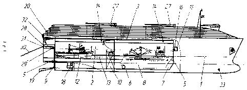
In Fig. 1, a starboard elevation of the dock vessel is presented.
In Fig. 2, a section of the dock vessel is presented along the level of
locating the
racks-ledges.
In Fig. 3, a general plan view of the dock vessel is presented.
In Fig. 4, a rear view of the dock vessel is presented.
In Fig. 5, a cross-section of the dock vessel is presented.
E) Best mode of realization of invention.
The dock vessel comprises a hull 1 with double bottom 6, inside the hull 1,
the
hangar 2 is situated which has a ceiling 3, side 4 and end walls 5, channel 7
located
in the bottom portion of the hangar 2 and designed for placement of large 8
ships,
stern 9 mobile gate and internal 10 mobile gate designed for dividing the
channel
with the view of safe arrangement of large 8 ships in the channel 7 and on the
rack-
ledges 11 located along the upper boundaries of the channel 7 with symmetric
deepening
CA 02810502 2013-03-05
8
to the right and to the left toward the hull 1. In this case, a width of racks-
ledges 11
should be not less than a width of medium 12 ship and a width of hangar 2 and
double bottom 6 is equal to the total width of the channel 7 and two racks-
ledges 11,
a height of hangar 2 from the double bottom 6 of hull 1 to a ceiling 3 of
hangar 2
should be not less than maximum height of a large 8 ship or distance from the
racks-
ledges 11 to a ceiling 3 of hangar should be not less than a height of medium
12
ship. At each of racks-ledges 11, not less than two medium 12 ships and not
less
than four small 13 ships are placed (a total of not less than four medium and
eight
small ships are housed) which are taken into the channel 7 using mobile
winches 14
mounted at a ceiling 3 of hangar 2. In this case, a length of hangar 2 is
equal to the
length of channel 7 and should be not less than two lengths of a large 8 ship.
The
ballast compartments (not shown in drawings) are arranged within the space
between the side 4 walls of hangar 2 and hull as well as in the double bottom
6 of
hull 1 of the dock vessel, fitted with flooding valves and vent valves (not
shown in
drawings). A niche 15 for installation of operating 16 winches is situated in
the fore
body of the dock vessel, at the height exceeding maximum level of water in the
channel 7; engine rooms 17 of the dock vessel are located under the racks-
ledges 11
in the afterbody with mounting of the screw propellers 18 on each side of the
channel 7. In the after body, the channel 7 has a trapezoidal expansion in
which the
V-type perforated ramp 19 is arranged, at that its fore part (not shown in
drawing) is
loosely joined with the double bottom 6 of hull 1 in the rear part of the
channel 7.
Along the perimeter of the upper part of the dock vessel, the light sensors
with
accumulators (energy storage units) 20 are mounted. In order to provide an
adequate
illumination level at work places inside the hangar, a ceiling 3 and side 4
walls are
fitted with hermetic LEDs (light emitted diodes) (not shown in drawings). The
freezing 21 tanks arranged in the hull 1 between hangar 2 and boards of hull 1
closer
to the double bottom 6, are designed for conservation of raw fish. The access
holes
22 for unloading of frozen products pass through the process compartments
CA 02810502 2013-03-05
9
23 and end at one of the decks of the hull 1 of the dock vessel. Tanks for
fuel, water
and process liquid (for example, oil) are located under the engine 17
compartment in
the double bottom 6, in the lower part of the hull 1 of the dock vessel. The
process
compartments 23 (compartments for processing of raw fish) are located over the
freezing 21 reservoirs; holds 24 for canning and finished products are
arranged over
the process compartments 23, and living accommodations (cabins) 25 are located
along the perimeter of hull 1 of the dock vessel, along the boards close to
light
sensors with accumulators 20 as well as in the fore and after parts of the
dock vessel.
At a ceiling 3 of hangar 2, the openings 26 are made in the form of access
holes of
holds 24 for canning and finished products. The openings 26 are designed for
natural
ventilation and for loading and unloading of large 8 ships and holds 24 of the
dock
vessel. The loading-unloading operations are performed by cranes 27 arranged
on
the upper deck 35 of the dock vessel. By the stern of the dock vessel, the
fish
working deck 28 is located at which the warp winches 29 are installed with
wound
on them warp 30 passing through the warp rollers 31. For control of the warp
winches 29, a trawl bridge 32 is placed over the hangar 2. In the fore part of
the hull
1, a thruster 33 is installed. A control of the vessel's stability is
exercised by means
of the automatic control system 34 placed in the trawl bridge 32. The
automatic
control system 34 controls a sequence and level of filling of the fore, stern
and board
ballast compartments (not shown in drawings).
The claimed invention works as follows.
The dock vessel is filled with ships. For entering of the ships inside the
hangar 2 of
the hull 1 of the dock vessel, the stern 9 mobile gate and internal 10 mobile
gate
open and the V-type perforated ramp 19 is turned down. The ballast
compartments
(not shown in drawings) overflood through the flooding valves as a result of
which a
ship submerges and hangar 2 is filled with water. A control of the dock vessel
CA 02810502 2013-03-05
10
flooding is exercised by the automatic control system 34 installed in the
trawl bridge
32 located over the hangar 2. The control system 34 regulates also the
oscillating
motions of the dock vessel through the antiroll stabilizers (not shown in
drawings).
The end 5 and side 4 walls of the hangar restrict the motions of ships inside
the hull
in case of pitching and rolling and contribute to fixation of ships in their
proper
locations. After flooding of a channel 7 and racks-ledges 11 of hangar 2 to
the draft
level of medium 12 and small ships 13, these ships enter a channel 7 and are
fixed in
proper locations of the racks-ledges 11, at that, the medium 12 ships enter
independently the racks-ledges 11 while small 13 ships are installed using the
mobile winches 14. Upon that, water is pumped out of the hangar 2 to a level
of a
channel 7 filling and a large ship 8 enters a channel 7 through the stern
mobile gate 9
and is arranged in the fore end of a channel 7. Upon that, the internal 10
mobile gate
closes and exhaustion of water out of the fore end of a channel 7 begins,
simultaneously with water pumping out, the following large ship 8 enters a
channel
7. After its arrangement in the rear part of the channel, the stern 9 mobile
gate close,
a ramp 19 is lifted and exhaustion of water out of the rear end of a channel 7
begins.
Upon completion of pumping out, main engines (not shown in drawing) are
started,
and the dock vessel 18 moves to the fishing area using the screw propellers
18. In
the fishing area, a channel 7 overfloods until the water level in the channel
7 rises to
the level of water surface outboard the dock vessel. Upon completion of
filling the
channel 7 with water, the stern 9 mobile gate opens, the V-type perforated
ramp
lowers and large 8 ship located in the rear end of a channel 7 leaves the
channel 7 in
reverse and proceeds to fishery. Subsequently, the fore end of the channel 7
is filled
with water, internal 10 mobile gate opens and the second large 8 ship leaves
the
dock vessel to start a fishery. Further, the water level in the channel 7
rises to the
water line of medium 12 and small 13 ships and they enter by turn the channel
7 and
move also to the fishing area. In this case, the manholes 26 of holds 24 for
canning
and finished products
CA 02810502 2013-03-05
11
are opened to remove the exhaust gases produced as a result of engine
operation of
large 8 ships.
Upon completion of fishing activities, the ships return to hangar 2 in the
reverse
sequence: at first, small 13, then medium 12 and, finally, large 8 ships. The
medium
12 ships are by pairs fixed on the racks-ledges 11 and, after accepting the
reports of
masters of terminating their fixation on the racks-ledges 11, the water
pumping out
of the channel 7 begins. Closing of internal 10 mobile gate of the channel is
also
performed when the wind and sea intensify. A decision of their closing is made
by
the leader of an expedition. The large 8 ships enter the channel 7 last,
because they
ensure safety of ships remaining on the sea. Upon completion of operation of
small
13 and medium 12 ships and their placing on the racks-ledges 11, the first
large 8
ship enters the channel and is fixed in the fore end of the channel 7. After
entering
the ships, the V-type perforated ramp 19 rises. In the course of entering the
ships, it
prevents a hard contact between ships entering the stern 9 mobile gate and
dock-
vessel, especially in case of pitching oscillation.
The second large 8 ship enters the channel, the stern 9 mobile gate closes and
water is pumped out of the rear end of the channel 7 and large 8 ship falls on
the
keel-blocks (not shown in drawing).
The fixation of ships in the channel 7 and on racks-ledges 11 is performed by
the
crew by a command of the officer of mooring operations and he takes also a
readiness report.
The heavy-tonnage ships can remain on the sea when deteriorating the
hydrometeorological conditions or perform the fishing activities over a
distance of
the dock vessel. Under these conditions, the dock vessel can carry out the
fishing
when medium 12 and small 13 ships are on-board. During fishing operations, the
fishing gear (not shown in drawing) with harvest is dragged to the rear part
of the
channel 7 using the operational winches 16 located in a niche 15 and fish is
taken
out of the cod end by standard fish pump or the cod end of the fishing gear is
freed
from fish with the aid of the mobile winches 14. A control over fishing
activities
CA 02810502 2013-03-05
12
is exercised from the trawl bridge 32, if the fishing gear is over the side of
ship,
operations within the hangar are executed by mobile 14 and operational 16
winches.
When the dock vessel performs the fishing activities, the fishing gears (not
shown in
drawing) are hauled in using the warp winches 29 with the warp 30 wound on the
winch drums of through the warp roll 31. Further, the fishing gear is
delivered into
the channel 7 using the operational winches 16 and the cod end (not shown in
drawing) is freed from fish. The harvest is directed to the process
compartments 23
for processing or freezing chambers 21 using the fish pumps or standard
conveyors.
In case of overload of the freezing chambers 21, an unloading of a part of
frozen
products is performed by cranes 27 through the manholes 22 of the freezing
chambers 21.
Changes in the dock vessel draft to the needed limits, stability control and
operation of stabilizers are initiated by the instructions of the automatic
control
system 34. Under the commands of the automatic control system 34, the proper
pumps and ballast compartments are turned on and turned off. In case of loss
of
control over the dock vessel's stability due to unfavorable sea state and wind
force,
the manual operation of these mechanisms is provided for using the automatic
control system 34. A manoeuvring of the dock vessel in the fishing area is
executed
with the use of screw propellers 18 and thruster 33. This allows not only to
efficiently manoeuvre but also provides a fail-safe going of ships into the
stern 9
mobile gate.
E) Industrial applicability.
The use of the claimed dock vessel as a transport vessel allows to quickly
deliver
to the fishing area a considerable quantity of ships of different types and to
deploy
the fishery expedition. In the fishing area, the dock vessel exercises the
functions of
the mother ship. In doing so, it conducts the maintenance of ships delivered
to the
fishing area, organizes the fishing activities, takes the harvest and
processes the raw
fish. The dock vessel can also carry out the independent fishing operations.
CA 02810502 2013-03-05
13
In addition, the dock vessel provides the comfort living conditions for the
crews of
ships of different types, especially, medium and small ships delivered by it
to the
fishing area and improves a safety of operation of these ships.