Note : Les descriptions sont présentées dans la langue officielle dans laquelle elles ont été soumises.
CA 02810876 2013-03-27
CUTTING MACHINE FOR WINDOW COVERINGS
BACKGROUND OF THE INVENTION
1. Field of the Invention
The present invention relates generally to a window covering, and more
particularly to a cutting machine for window coverings.
2. Description of the Related Art
Typically, there are two types of window blinds, which are venetian blinds
and vertical blinds. In the present days, a consumer can buy window blinds in
a store,
and the window blinds are cut right in the store to meet the demand of the
consumer.
The conventional venetian blind has several components, typically including
a top rail, a bottom rail, and slats. Each component may have specified size
and
material. For example, the top rail and the bottom rail usually are made of
strong metal,
and the slats are made of light materials, like aluminum or PVC. It is obvious
that these
components shouldn't be cut by the same cutter due to different properties of
different
materials. However, the common cutting machine in the market only has one
cutter,
and such cutting machines are taught in U.S. Patent Numbers 6,761,099 and
6,681,673.
An improved cutting machine is provided with various cutters for different
components of window blinds. Such cutting machine has two or more motors to
drive
the cutters respectively. But such cutting machines are complex and expensive.
Furthermore, all the conventional cutting machines as mentioned above can
only cut one type of window blinds, which is not efficient.
SUMMARY OF THE INVENTION
The primary objective of the present invention is to provide a cutting
CA 02810876 2013-03-27
machine for window coverings, which may cut two or more types of window
blinds. It
has a simple structure and is easy to operate.
According to the objective of the present invention, the components of the
window coverings include a horizontal top rail, a horizontal bottom rail and
horizontal
slats of a venetian blind, and a vertical top rail and vertical slats of a
vertical blind, and
a cutting machine for cutting the components of window coverings includes a
machine
base for the components, a first cutting unit and a second cutting unit; the
machine
base is a substantially elongated member, which has a long axis and a short
axis,
wherein the machine has a first side and an opposite second side along the
long axis,
and has a third side and an opposite fourth side along the short axis; the
first cutting
unit is provided on the machine base and adjacent to the first side, including
a base, a
slat holding device, a cutter device, and a driving device; the base has a
first bore and a
first positioning bore to receive the horizontal slats and the horizontal top
rail
respectively; the slat holding device has a pressing block and a pushing
member,
wherein the pressing block is movably received in the first bore of the base
and has a
bore to receive the horizontal bottom rail; the pushing member moves the
pressing
block toward the first positioning bore; the cutter device is movably provided
on the
base, which has a first cutter and a second cutter which are adjacent to the
first bore
and the first positioning bore respectively, and the first cutter is used to
cut off the
horizontal slats and the horizontal bottom rail, the second cutter is used to
cut off the
horizontal top rail; and the driving device has a connecting member and an
operating
member, wherein the connecting member is connected to the cutter device, and
the
operating member is connected to the connecting member to move the cutter
device;
the second cutting unit is movably mounted on the machine base, which
comprises a
frame, a cutter, and a controller; the frame is movably provided on the
machine base
2
CA 02810876 2013-03-27
for a movement along the long axis of the machine base; the cutter is movably
provided in the frame, wherein a second bore is formed between the cutter and
the
frame to receive the vertical slats; and the controller is connected to the
cutter to move
the cutter; wherein the frame has a movable base and two rails; the movable
base is
movably mounted on the machine base, and the rails are connected to the
movable
base; the rails are vertical to the movable base and are parallel to the short
axis of the
machine base; the cutter is provided between the rails with opposite sides
engaging the
rails; and the controller moves the cutter to move in the rail to cut the
vertical slats off.
In an embodiment, the pushing member of the slat holding device of the first
cutting unit has a block, a shaft, and a flexible member; the block is
connected to the
connecting member; the block has a opening, and the base has an opening; the
shaft
passes through the opening of the block and the opening of the base to connect
to the
pressing block; the flexible member is provided on the shaft and is between
the block
and the base to move the pressing block.
In an embodiment, the shaft has a protrusion at a side adjacent to the
pressing block; the protrusion is outside of the base; and the flexible member
is
between the protrusion and the block.
In an embodiment, the second cutting unit's cutter is provided with a slot
parallel to the short axis of the machine base; and the controller includes a
sliding
block, a linkage, and a control bar; the sliding block is received in the slot
of the cutter
to move in the slot; the linkage is pivoted on the sliding block; and the
control bar is
pivoted on the frame and engages the linkage, whereby when the control bar is
moved,
the cutter is moved via the linkage and the sliding block.
In an embodiment, the cutting machine further comprises a second restricting
unit which has a fixing base and a restricting board; the fixing base is
connected to the
3
CA 02810876 2013-03-27
second side of the machine base, and the restricting board is movably provided
on the
fixing base to move along the long axis of the machine base.
In an embodiment, the cutting machine further comprising a first restricting
unit provided on the machine base, wherein the first restricting unit is
closer to the first
side than the first cutting unit; the first restricting unit has a stop
device, a transmitting
device, and a fixing device; the stop device is beside the first cutting unit;
the
transmitting device is connected to the stop device and the driving device;
when the
driving device moves the cutter along the short axis of the machine base, the
driving
device moves the stop device between a first position and a second position,
wherein
the first position is closer to the cutter device than the second position; at
the first
position, the stop device rests against ends of the horizontal bottom rail and
the
horizontal slats in the first bore and the horizontal top rail in the first
positioning bore;
the fixing device is connected to the machine base; the transmitting device
rests against
the stop device when the stop device is on the first position, and the
transmitting device
leaves the stop device when the stop device moves toward the second position
from the
first position.
In an embodiment, the transmitting device has a transmitting board, a
transmitting shaft, a first supporting shaft, a second supporting shaft, and a
locking
member; the transmitting board is pivoted on the machine base through an axle;
the
transmitting board has a slot; the transmitting shaft has an end connected to
the
connecting member of the driving device to move with the cutter device; the
transmitting shaft has a post on an opposite end to engage the slot of the
transmitting
board; the first supporting shaft has an end fixed to the machine base and an
opposite
end engaging and passing through the stop device, whereby the stop device is
free to
move between the first position and the second position relative to the first
supporting
4
CA 02810876 2013-03-27
shaft; the second supporting shaft has an end engaging the base and an
opposite end
pivoted on the transmitting board; the locking member is connected to the
second
supporting shaft; the locking member is provided with a scale to secure the
stop device
at a specific position on the second supporting shaft; when the driving device
moves
the cutter device and the transmitting shaft, the post moves in the slot to
swing the
transmitting board which will move the second supporting shaft in a direction
away
from the base, as a result, the stop device is moved in a direction away from
the first
bore and the first positioning bore.
In an embodiment, the transmitting board of the transmitting device is closer
to the first cutting unit than the fixing device of the first restricting
member to be move
to rest against or leave the fixing device.
In an embodiment, the connecting member of the driving device is a rack;
the rack has teeth meshed with a gear set; and the gear set is connected to
the operating
member.
In an embodiment, the base is further provided with a second positioning
bore adjacent to the first positioning bore to receive the vertical top rail;
the first bore,
the first positioning bore and the second positioning bore are located in
order along the
short axis of the machine base; the cutter device further has a third cutter
beside the
second positioning bore to cut the vertical top rail.
Therefore, the aforementioned cutting machine for window coverings has a
simple structure, and is easy to operate. Moreover, it has the ability to cut
components
of different types of window blinds.
5
CA 02810876 2013-03-27
BRIEF DESCRIPTION OF THE DRAWINGS
FIG. 1 is a perspective view of a preferred embodiment of the present
invention;
FIG 2 is a perspective view of the preferred embodiment of the present
invention, showing the first cutting unit and the first restricting unit;
FIG. 3 is a rear view of FIG 2;
FIG. 4 is a perspective view of the preferred embodiment of the present
invention, showing the base and the cutter device;
FIG 5 is a top view of the preferred embodiment of the present invention,
showing the stop device of the first restricting unit in the first position;
FIG 6 is a top view of the preferred embodiment of the present invention,
showing the stop device of the first restricting unit in the second position;
FIG 7 and FIG. 8 are right views of the second cutting unit of the preferred
embodiment of the present invention, showing the cutter moving along the rail;
and
FIG 9 is a perspective view of the second restricting unit of the preferred
embodiment of the present invention.
DETAILED DESCRIPTION OF THE INVENTION
FIG 1 shows a cutting machine of the preferred embodiment of the present
embodiment, which is designed for cutting components of venetian blinds,
vertical
blinds, and any other types of window blinds. The venetian blind has a
horizontal top
rail, a horizontal bottom rail, and a plurality of horizontal slats. The
vertical blind has a
vertical top rail and a plurality of vertical slats. The size and structure of
these
components of the window blinds are well known for a person who is skilled in
the art,
so we do not describe the relating details here. As shown in FIG 1, the
cutting machine
6
CA 02810876 2013-03-27
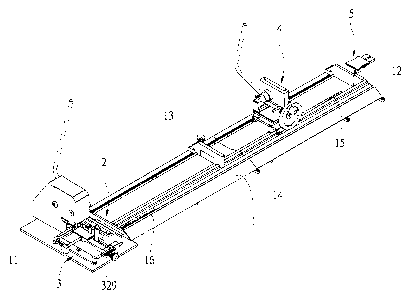
has a machine base 1, a first cutting unit 2, a first restricting unit 3, a
second cutting
unit 4, and a second restricting unit 5.
The machine base 1 is a substantially elongated rectangular member. The
components of the window blinds are put on the machine base 1 parallel to a
long axis
of the machine base 1, and are movable along the long axis. The machine base 1
has a
first side 11 and a second side 12 at the opposite sides of the long axis, and
has a third
side 13 and a fourth side at the opposite sides of a short axis which is
vertical to the
long axis. The machine base 1 is provided with a first scale 15 and a second
scale 16
on a top side thereof. The first scale 15 is located adjacent to the second
side 12, and
the second scale 16 is adjacent to the first side 11.
As shown in FIG 2 to FIG 4, the first cutting unit 2 is designed for cutting
the horizontal top rails, the horizontal bottom rails, the horizontal slats of
the venetian
blinds, and the vertical top rails of the vertical blinds. The first cutting
unit 2 is
provided on the machine base 1 and is adjacent to the first side 11. The first
cutting
unit 2 has a base 21, a cutter device 23, a driving device 24, and a slat
holding device.
The base 21 is provided on the machine base 1, and has a first bore 211, a
first positioning bore 212, and a second positioning bore 213 located in order
from the
third side 12 to the fourth side 14. The horizontal slats, the horizontal top
rail and the
vertical top rail may respectively engage the first bore 211, the first
positioning bore
212, and the second positioning bore 213. The first positioning bore 212 and
second
positioning bore 213 respectively have a specified shape which fits cross
sections of
the horizontal top rail and the vertical top rail.
The cutter device 23 is provided on the base 21, and is able to move along
the short axis of the machine base 1. The cutter device 23 has a first cutter
231, a
second cutter 232, and a third cutter 233, which are in association with the
first bore
7
CA 02810876 2013-03-27
211, the first positioning bore 212, and the second positioning bore 213
respectively.
The driving device 24 is provided on the machine base 1, which has a
connecting member 241 and an operating member. The connecting member 241 is
connected to the cutter device 23, and is controlled by the operating member
to move
along the short axis of the machine base 1. In this embodiment, the connecting
member
241 is a toothed rack parallel to the short axis of the machine base 1, and
the operating
member has a handle 242 and a gear set 243. The gear set 243 is meshed with
the rack
241, and is connected to the handle 242. Therefore, turning the handle 242 may
rotate
the gear set 243, and then move the rack 241, as well as the cutter device 23.
The slat holding device is provided on the machine base 1, which has a
pressing block 22 and a pushing member 25. The pressing block 22 is received
in the
first bore 211 and is adjacent to the third side 13. The pressing block 22 is
able to move
along the short axis of the machine base 1 within the first bore 211. The
pressing block
22 has a bore 221 to engage the horizontal bottom rail, and the shape of the
bore 221
fits the cross section of the horizontal bottom rail. The pushing member 25
has a block
251, a shaft 252, and a flexible member 253. The block 251 is provided on the
connecting member 241. The block 251 has an opening (not shown). The shaft 252
is
inserted into the opening of block 251 and an opening (not shown) on the base
21, and
then the shaft 252 is connected to the pressing block 22 in the first bore
211. The shaft
252 has a protrusion 254 at a side adjacent to the pressing block 22, and the
protrusion
254 is outside of the base 21. The flexible member 253 is a spring in the
present
embodiment. The spring 253 fits the shaft 252, and is located between the
protrusion
254 and the block 251 to push the block toward the fourth side 14 through the
shaft
252.
As shown in FIG 1, FIG. 2, FIG 5, and FIG 6, the first restricting unit 3 is
8
CA 02810876 2013-03-27
provided on the machine base 1. The first cutting unit 2 is closer to the
second side 12
than the first restricting unit 3. The first restricting unit 3 includes a
stop device 31, a
transmitting device 32, and a fixing device 33.
The stop device 31 is a substantially elongated plate on a side of the base 21
where corresponding to the first bore 211, the first positioning bore 212 and
the second
positioning bore 213. The stop device 31 is closer to the first side 11 than
the base 21.
The stop device 31 has a slot 311 on a bottom side thereof. The slot 311 is an
elongated
slot parallel to the long axis of the machine base 1.
The transmitting device 32 is connected to the stop device 31 and the driving
device 24 to move the stop device 31 between a first position (FIG 5) and a
second
position (FIG 6) while the driving device 24 is moving the cutter device 23.
The first
position is closer to the cutter device 23 than the second position. The
transmitting
device 32 has a transmitting board 321, a transmitting shaft 322, a first
supporting shaft
323, a second supporting shaft 324, and a locking member 325. The transmitting
board
321 is an elongated board pivoted on the machine base 1 through an axle 326.
The
transmitting board 321 has a slot 327. The transmitting shaft 322 has an end
connected
to the connecting member 241 of the driving device 24 to move with the cutter
device
23, and the other end of the transmitting shaft 322 is provided with a post
328. The
post 328 engages the slot 327 of the transmitting board 321. The first
supporting shaft
323 has an end fixed to the machine base 1 and the other end engaging the slot
311 of
the stop device 31. The stop device 31 is able to move on the supporting shaft
323
between the first position and the second position. The second supporting
shaft 324 has
an end passing through the base 21 and the other end pivoted on the
transmitting board
321. The second supporting shaft 324 is pivoted on a side of the transmitting
board 321,
which is opposite to the slot 327. The second supporting shaft 324 is able to
move
9
CA 02810876 2013-03-27
along the long axis of the machine base 1 relative to the base 21. The stop
device 31 is
fixed onto the second supporting shaft 324 at a predetermined position by the
locking
member 325.
The fixing device 33 is a cube in the present embodiment. The fixing device
33 is fixed to the machine base 1, and is adjacent to the transmitting board
321. The
transmitting board 321 is closer to the first cutting unit 2 than the fixing
device 33. The
transmitting board 321 touches the fixing device 33 when the stop device 31 is
moved
to the first position (FIG 5), and the transmitting board 321 leaves the
fixing device 33
when the stop device 31 is moved toward the second position (FIG 6). The
locking
member 325 has a third scale 329.
When a user wants to cut the horizontal slats, the horizontal top rail and the
horizontal bottom rail of a venetian blind with the cutting machine of the
present
invention, the user has to adjust the location of the stop device 31 using the
third scale
329 of the locking member 325, and then lock the locking member 325 to secure
the
stop device 31 at a specified position on the second supporting shaft 324. At
this time,
the stop device 31 is at the first position, as shown in FIG 5. Next, the user
has to put
the components of the venetian blind in the bores 211, 212, 221 (specifically,
the
horizontal slats for the first bore 211, the horizontal top rail for the first
positioning
bore 212, and the horizontal bottom rail for the bore 221), and push them
toward the
first side 11 until they touch the stop device 31. If the user wants to cut
the vertical top
rail of a vertical blind, he/she has to put the rail in the second positioning
bore 213 and
adjust a location of the vertical top rail with the second scale 16.
Next, the user operates the handle 242 to move the cutter device 23 toward
the fourth side 14. As a result, the cutters 231-233 will cut the components
off
respectively.
CA 02810876 2013-03-27
As shown in FIG 5 and FIG 6, the transmitting shaft 322 moves with the
driving device 24, so that it will move the post 328 along the slot 327 and
the
transmitting board 321 at the same time. As a result, the second supporting
shaft 324 is
moved in a direction away from the base 21. The stop device 31, which moves
with the
second supporting shaft 324, is moved to the second position from the first
position. As
a result, it is easy to remove the waste material after cutting from the first
cutting unit
2.
The top and bottom rails of the blinds usually are bent plates, and the rails
all
have a transverse middle section and two vertical side sections at opposite
ends of the
middle section. The bores 212, 213, 221 are shaped respectively to fit the
rails, and
they have a middle portion for fitting the middle section of the rails, and
two side
portions for fitting the side sections. The middle portions of the bores 212,
213, 221 are
closer to the corresponding cutters 231-233 than the side portions. In other
words, the
middle section of the rails will be first portion to be cut when the cutters
231-233 are
used to cut the rails.
When the user put horizontal slats in the first bore 211, he/she may operate
the handle 242 to move the pressing block 22 via the connecting member 241,
the
block 251, the flexible member 253, the protrusion 254, and the shaft 252, so
that the
pressing block 22 presses the slats to hold them. The flexible member 253
cushions the
pressure on the slats to avoid making indents on the slats.
While the stop device 31 is at the first position, and the rails or slats are
put
in the corresponding bores, the transmitting board 321 is rested against the
fixing
device 33 to avoid the transmitting device 32 and the stop device 31 from
being moved
by the rails or slats. It will firmly secure the stop device 31 to increase
the accuracy in
cutting.
11
CA 02810876 2013-03-27
As shown in FIG 7 to FIG 9, the second cutting unit 4 and the second
restricting unit 5 are provided to precisely cut the vertical slats of the
vertical blinds.
The second cutting unit 4 has a frame 41, a cutter 42, and a controller. The
frame 41 is
provided on the machine base 1, which has a movable base 411 and two rails
412. The
movable base 411 has two wheels sets 413, and therefore the movable base 411
may
freely reciprocate along the long axis of the machine base 1. The rails 412
are mounted
on the movable base 411 at a side opposite to the wheel sets 413. The rails
412 are
parallel with each other, and they are set parallel to the short axis of the
machine base 1.
The cutter 42 is provided in the frame 41. The cutter 42 is set between the
rails 412 and
engages the rails 412 with both sides, so that the cutter 42 is able to move
vertically. A
second bore 46 is formed between the cutter 42 and the rails 412 to receive
the slats.
The cutter 42 has a slot 421 parallel to the short axis of the machine base 1.
The
controller is connected to the cutter 42 to move the cutter 42. In an
embodiment, the
controller has a sliding block 43, a linkage 44, and a control bar 45. The
sliding block
43 is received in the slot 421 of the cutter 42 and moves along the slot 421.
The
linkage 44 has opposite ends pivoted respectively on the sliding block 43 and
the
control bar 45, and the control bar 45 is further pivoted on the frame 41 to
form a
four-linkage mechanism. When a user operates the control bar 45, it will move
the
cutter 42 up and down via the four-linkage mechanism.
The second restricting unit 5 has a fixing base 51 and a restricting board 52.
The fixing base 51 is provided to the second side 12 of the machine base 1.
The fixing
base 51 has a slot 511 along the long axis of the machine base 1. The
restricting board
52 is provided on the fixing base 51 and engages the slot 511, therefore the
restricting
board 52 is able to move along the long axis of the machine base 1.
While operating, a user moves the second cutting unit 4 to a specified
12
CA 02810876 2013-03-27
position according to the first scale 15, and then puts the vertical slats in
the second
bore 46 and lets the vertical slats touch the restricting board 52 of the
second
restricting unit 5. After securing the vertical slats, the user moves the
restricting board
52 in a direction away from the second cutting unit 4 to separate the
restricting board
52 from the vertical slats, and then operates the control bar 45 to let the
cutter 42 cut
the slats.
As a result, the vertical slats are precisely cut with the help of the
restricting
board 52. If another vertical slats have to be cut for the same size, it
doesn't need to
move the second cutting unit 4. Furthermore, moving the restricting board 52
in a
direction away from the second cutting unit 4 before cutting is helpful to a
fine cut of
the slats. The waste materials of cutting are left between the second cutting
unit 4 and
the second restricting unit 5. The user may remove the waste material easily
because of
moving away of the restricting board 52 before cutting.
The cutting machine of the present invention may cut the components of
blinds in an easy way. It may cut different components by different cutters at
the same
time. The description above is only a few preferred embodiments of the present
invention and the equivalence of the present invention is still in the scope
of claim
construction of the present invention.
13