Note : Les descriptions sont présentées dans la langue officielle dans laquelle elles ont été soumises.
WO 2012/113070 CA 02810946 2013-03-08 PCT/CA2012/000173
DISPENSER FOR A CONTAINER
TECHNICAL FIELD
[0001] The present disclosure is directed at a dispenser for a
container. More
particularly, the present disclosure is directed at a dispenser for a
container that includes a
flexible fluid conduit that can be squeezed shut to prevent fluid from
escaping the container.
BACKGROUND
[0002] Millions of bottled beverages are sold annually. Some of these
beverages are
carbonated, in which case the bottle and the dispenser used to contain the
beverage should be
designed to address the challenges accompanying storing and dispensing
carbonated beverages.
Research and development accordingly continues into dispensers designed
particularly to be
used to dispense carbonated beverages.
BRIEF DESCRIPTION OF THE DRAWINGS
[0003] In the accompanying drawings, which illustrate one or more
exemplary
embodiments:
[0004] Figures 1 and 2 depict sectional views of a dispenser, according
to one
embodiment, that is attached to a container and that is in closed (Figure 1)
and opened (Figure 2)
positions.
[0005] Figures 3(a) and 3(b) depict sectional and front elevation views
of a base portion
of the dispenser of Figure 1, and Figure 3(c) depicts a sectional view of the
base portion taken
along line A-A of Figure 3(b).
[0006] Figure 4 depicts a perspective view of a squeezing element that
is included in the
dispenser of Figure 1.
[0007] Figures 5(a) and 5(b) depict sectional views of the dispenser,
according to another
embodiment, in which the dispenser is mounted to a conventional bottle cap and
in which the
dispenser is shown in closed (Figure 5(a)) and opened (Figure 5(b)) positions.
- 1 -
WO 2012/113070 CA 02810946 2013-03-08
PCT/CA2012/000173
[0008] Figures 6(a) and 6(b) depict exploded and perspective views,
respectively, of
portions of the dispenser of Figure 5(a).
[0009] Figure 7 depicts a side elevation view of the dispenser and
the container to which
the dispenser is attached, according to another embodiment in which the
dispenser includes an
embodiment of a flavour dispensing unit.
[0010] Figure 8 depicts a sectional view of the embodiment of the
flavour dispensing unit
included in the dispenser of Figure 7.
[0011] Figures 9(a) and 9(b) depict sectional views of the
dispenser, according to another
embodiment that includes a conduit retaining unit, in closed (Figure 9(a)) and
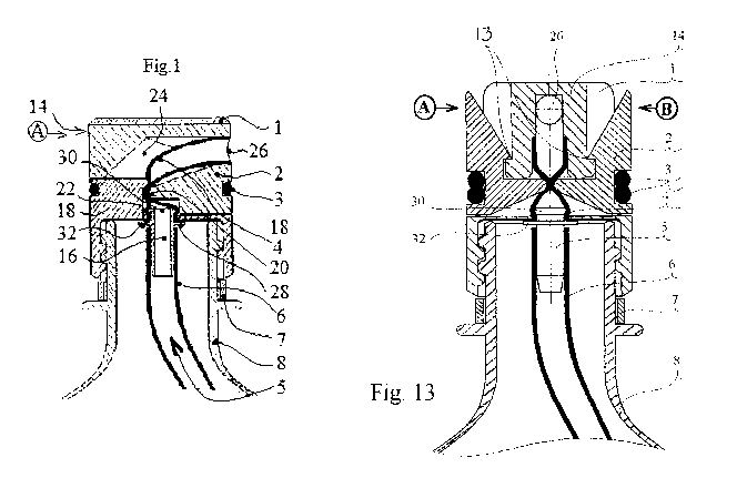
opened (Figure
9(b)) positions.
[0012] Figures 10 and 11 depict sectional views of the dispenser,
according to another
embodiment that lacks a sealing element, in closed (Figure 10) and opened
(Figure 11) positions.
[0013] Figures 12(a) and 12(b) depict sectional and front elevation
views of the
dispenser, according to another embodiment that lacks a sealing element and in
which the
dispenser is mounted to a conventional bottle cap.
[0014] Figures 13 and 14 depict sectional views of the dispenser,
according to another
embodiment, that is attached to the container and that is in closed (Figure
13) and opened (Figure
14) positions.
[0015] Figure 15(a) depicts a perspective view of the base portion
of the dispenser of
Figure 13.
[0016] Figure 15(b) depicts a sectional view of the base portion of
Figure 15(a) taken
along line B-B.
[0017] Figure 15(c) depicts a side cutaway view of the base portion
taken along line A-A
of Figure 15(b).
- 2 -
WO 2012/113070 CA 02810946 2013-03-08
PCT/CA2012/000173
[0018] Figures 16(a), 16(b) and 16(c) depict perspective, side
elevation, and top plan
views of one of the squeezing elements that is included in the dispenser of
Figure 13.
[0019] Figure 17 depicts a side elevation view of the dispenser
shown in Figure 13
attached to the container, in which the dispenser includes another embodiment
of the flavour
dispensing unit.
[0020] Figure 18 depicts a sectional view of the embodiment of the
flavour dispensing
unit of Figure 17.
[0021] Figure 19 depicts a sectional view of the dispenser,
according to another
embodiment that includes the conduit retaining unit.
SUMMARY
[0022] According to one aspect, there is provided a dispenser for a
container. The
dispenser includes a base portion couplable to the container, wherein the base
portion comprises
a port through which fluid exiting the container passes when the base portion
is coupled to the
container; an external flexible fluid conduit fluidly coupled to the port,
wherein the external fluid
conduit is located outside of the container when the base portion is coupled
to the container; and
a squeezing element coupled to the base portion and movable between a closed
position in which
the squeezing element squeezes the external fluid conduit shut to prevent the
fluid from flowing
therethrough and an opened position in which the squeezing element is
positioned such that the
fluid can flow through the external fluid conduit.
[0023] The squeezing element may be slidable on the base portion
between the opened
and closed positions.
[0024] The dispenser may also include a tension band wrapped along
the base portion
and the squeezing element to bias the squeezing element in the closed
position.
[0025] The base can include a shoulder located adjacent one half of
the external fluid
conduit and the squeezing element can include a projection located adjacent
the other half of the
external fluid conduit. The projection can squeeze the external fluid conduit
against the shoulder
when the squeezing element is in the closed position.
- 3 -
WO 2012/113070 CA 02810946 2013-03-08
PCT/CA2012/000173
[0026] The shoulder can have a recess that is aligned with the
projection and into which
the external fluid conduit is pushed when the squeezing element is in the
closed position.
[0027] The squeezing element can include an exit path terminating
at a dispenser opening
located along an outer surface of the dispenser and the external fluid conduit
can extend along
the exit path and terminate at the dispenser opening to allow the fluid to
exit via the dispenser
opening when the squeezing element is in the opened position.
[0028] According to another aspect, there is provided a dispenser
for a container that
includes a base portion couplable to the container that comprises a port
through which fluid
exiting the container passes when the base portion is coupled to the
container; an external
flexible fluid conduit fluidly coupled to the port that is located outside of
the container when the
base portion is coupled to the container; and at least two squeezing elements
pivotally coupled to
the base portion and movable between a closed position in which the squeezing
elements
collectively squeeze the external fluid conduit shut to prevent the fluid from
flowing
therethrough and an opened position in which the squeezing elements are
positioned such that
the fluid can flow through the external fluid conduit.
[0029] Each of the squeezing elements may include a fulcrum and a
projection and the
base portion may include a pair of ledges each supporting one of the fulcrums.
The squeezing
elements may pivot on the fulcrums as they transition between the closed and
opened positions
and the projections may collectively squeeze the external fluid conduit when
the squeezing
elements are in the closed position.
[0030] The dispenser may also include a tension band wrapped
around the base portion
and the squeezing elements to bias the squeezing elements to the closed
position.
[0031] The fulcrums may be located midway along the squeezing
elements and the
projections may be located nearer to the container than the fulcrums.
[0032] The dispenser may include an internal fluid conduit fluidly
coupled to the port
and located inside the container when the base portion is coupled to the
container.
- 4 -
WO 2012/113070 CA 02810946 2013-03-08
PCT/CA2012/000173
[0033] The internal and external fluid conduits may be different
portions of a flexible
tube.
[0034] The dispenser may also include a sealing element that is
positioned between the
external fluid conduit and the perimeter of the port to create a fluidic seal
between the external
fluid conduit and the perimeter of the port.
[0035] The sealing element can include a hollow member inserted
through the port
through which the fluid exiting the container passes, wherein the hollow
member has wrapped on
one end portion the external fluid conduit and wrapped on another end portion
the internal fluid
conduit and wherein the external fluid conduit is sandwiched between the
hollow member and
the perimeter of the port; and a fluid conduit flange located on the hollow
member between the
hollow member and the external fluid conduit that helps retain the external
fluid conduit on the
hollow member.
[0036] The dispenser may also include an internal flange located on a
portion of the
hollow member located within the container when the base portion is coupled to
the container
and sized to press against a surface around the port to prevent the sealing
element from being
pulled from the container.
[0037] The dispenser may also include a conduit retaining unit coupled
to the internal
fluid conduit. The conduit retaining unit can have a plurality of arms each
being sufficiently
long to press against the interior of the container such that the conduit
retaining unit is secured
within the container when located therein.
[0038] The dispenser may also include a flavour dispensing unit
fluidly coupled to an
end of the internal fluid conduit into which the fluid enters. The flavour
dispensing unit may
have a housing having an inlet into which the fluid is drawn and an outlet
fluidly coupled to the
end of the internal fluid conduit into which the fluid enters; a flavour block
contained within the
housing; and a fluid channel through which the fluid passes as it travels from
the inlet to the
outlet and fluidly coupled to the flavour block such that portions of the
flavour block dissolve
into the fluid as the fluid flows through the fluid channel.
- 5 -
WO 2012/113070 CA 02810946 2013-03-08
PCT/CA2012/000173
[0039] The base portion may be threaded to allow it to be directly
screwed on to the
container and over a mouth of the container. The base portion, except for the
port, can seal the
mouth of the container. The base portion may also have a planar surface via
which the base
portion may be mounted on to a bottle cap.
[0040] This summary does not necessarily describe the entire scope of
all aspects. Other
aspects, features and advantages will be apparent to those of ordinary skill
in the art upon review
of the following description of specific embodiments.
DETAILED DESCRIPTION
[0041] Directional terms such as "top", "bottom", "upwards",
"downwards", "vertically"
and "laterally" are used in the following description for the purpose of
providing relative
reference only, and are not intended to suggest any limitations on how any
article is to be
positioned during use, or to be mounted in an assembly or relative to an
environment.
[0042] Several problems and challenges arise when dispensing a
carbonated beverage
from a bottle. One problem is that repeatedly removing a bottle cap from the
bottle releases the
carbon dioxide contained in the bottle and therefore tends to cause the
beverage to go flat over
time. This makes the beverage less pleasant to drink, and can result in
consumers discarding the
beverage instead of drinking it. Alternatives exist to bottle caps that have
to be removed each
time the beverage is to be dispensed. For example, some types of dispensers
for containers
utilize a piston assembly in which a consumer reciprocates the piston in order
to pump a liquid,
such as a beverage, from the container. Detrimentally, however, these piston-
type dispensers
require pumping, which can be cumbersome, and are relatively complex in that
they typically
rely on springs, which can increase manufacturing and maintenance costs.
Another type of
dispenser is one that utilizes a carbon dioxide cartridge to drive the liquid
out of the container.
The use of such a cartridge, however, again introduces cost and complexity to
the manufacturing
and maintenance process.
[0043] Other kinds of dispensers that do not have to be removed in
order to dispense
liquids from a container typically suffer from similar faults. For example, it
is common for such
dispensers to utilize a flow path that results in the liquid being splashed
and agitated as it exits
the container, which can cause a carbonated beverage to go flat. Furthermore,
these dispensers
- 6 -
WO 2012/113070 CA 02810946 2013-03-08
PCT/CA2012/000173
often rely on gaskets used to seal valve assemblies or other similar seals to
prevent leakage from
the container; over time, these gaskets can fail and leaking can result.
Additionally, the relative
complexity of these dispensers often results in their being made from a
variety of different
materials, which can render them not recyclable.
[0044] The embodiments described herein are directed at a dispenser
for a container
(such as a bottle) that can be used to dispense fluids, such as carbonated
beverages and other
liquids, from the container. Without removing the dispenser from the
container, the dispenser
can be used to seal the container shut and to dispense the fluids from the
container. In order to
seal the container, a flexible fluid conduit, such as a flexible tube, is
squeezed shut. Squeezing
the conduit shut does not require a gasket or other similar type of seal, and
therefore is more
resilient and reliable than many types of conventional dispensers. In some
embodiments the
liquid is dispensed from the container through the flexible fluid conduit and
then directly out of
the dispenser. In these embodiments, the liquid flows smoothly and with
relatively minimal
agitation through the flexible fluid conduit, which can help prevent the
liquid from losing
carbonation.
[0045] Referring now to Figures 1 and 2, there are depicted side
sectional views of one
embodiment of a dispenser 14 attached to a container 8. In Figure 1, the
dispenser 14 is in a
closed position and fluid (not shown) contained within the container 8 is
sealed within the
container. In Figure 2, the dispenser 14 is in an opened position and the
fluid contained within
the container 8 can flow out of the container 8.
[0046] The dispenser 14 has a base portion 1 that is attached to the
container 8 by virtue
of being screwed on to a neck of the container 8. At the bottom of the base
portion 1 is a ring 7
to which the base portion 1 is frangibly connected, and which helps to keep
the base portion 1
from inadvertently being screwed off of the container 8. The base portion 1
covers the entire
mouth of the container 8 with the exception of a portion of the container 8's
mouth left
uncovered by a port 16 in the base portion 1. Fluid exiting the container 8
exits via the port 16.
On the outside of the container 8, an external flexible fluid conduit 4 is
present and is fluidly
coupled to the port 16. The fluid exiting the container 8 travels through the
port 16, into the
- 7 -
WO 2012/113070 CA 02810946 2013-03-08
PCT/CA2012/000173
external fluid conduit 4, and then out of an outer surface of the dispenser 1
when the fluid is
dispensed.
[0047] As also shown from different perspectives in Figures 3(b) and
(c), discussed
below, the base portion 1 has a channel 44 into which a squeezing element 2 is
inserted and
along which the squeezing element 2 is slidable. The squeezing element 2
includes a projection
20 that is slidable towards a shoulder 18 that forms part of the base 1.
Between the shoulder 18
and the projection 20 is the external fluid conduit 4. In Figure 1, the
squeezing element 2 is
positioned such that the projection 20 squeezes the external fluid conduit 4
against the shoulder
18 in order to prevent any of the fluid within the container 8 from travelling
through the external
fluid conduit 4; in this state, the squeezing element 2 is referred to as
being in the "closed"
position. With sufficient force, the squeezing element 2 can squeeze the
external fluid conduit 4
shut to stop any fluid in the container 8 from travelling through the external
fluid conduit 4 when
in the closed position. In Figure 2, the squeezing element 2 is positioned to
apply relatively less
force to the external fluid conduit 4 such that the external fluid conduit 4
is sufficiently released
to allow the fluid exiting the container 8 through the port 16 to travel
through the external fluid
conduit 4; in this state, the squeezing element 2 is referred to as being in
the "opened" position.
A tension band 3 is wrapped around the exteriors of the shoulder 18 and the
squeezing element 2
in order to bias the squeezing element 2 into the closed position. When a
consumer wants to
dispense the fluid, the consumer may push the squeezing element 2 at the
location labelled "A"
in Figure 1 such that the biasing force of the tension band 3 is overcome and
the squeezing
element 2 transitions to the opened position. When the consumer ceases
pushing, the force from
the tension band 3 causes the squeezing element 2 to return to the closed
position.
[0048] In Figures 1, 2, 13, and 14 the dispenser 14 includes a sealing
element 5 that is
inserted through the port 16 and that helps maintain a fluid tight seal
between the external fluid
conduit 4 and the container 8. The sealing element 5 includes a hollow member
28 that is
inserted through the port 16 and that has wrapped on one end portion of the
external fluid
conduit 4. At an end of the hollow member 28 that is located outside of the
container 8 is an
external flange 30. The external fluid conduit 4 is sheathed over the external
flange 30 and is
sandwiched at a point along its length between the perimeter of the port 16
and the hollow
member 28. This compression of the external fluid conduit 4 between the
perimeter of the port
- 8 -
WO 2012/113070 CA 02810946 2013-03-08
PCT/CA2012/000173
16 and the hollow member 28 helps to create a fluidic seal between the
external fluid conduit 4
and the perimeter of the port 16. The fluidic seal not only helps to prevent
liquid from
inadvertently escaping from the container 8, but helps to prevent gas from
escaping as well,
which is particularly beneficial when dispensing carbonated beverages.
[0049] On the portion of the sealing element 5 located within the
container 8, there is an
internal fluid conduit 6 wrapped on the other end portion of the hollow member
28. As shown in
Figure 7 and 17, the internal fluid conduit 6 extends downwards into the
container 8 and, when
the container 8 is sufficiently filled with liquid, the end of the internal
fluid conduit 6 not
attached to the sealing element 5 is submerged in the liquid. Consequently,
assuming all seals
are functioning properly, only or primarily the liquid is dispensed from the
container 8 via the
internal fluid conduit 6, and undissolved gases do not escape the container 8
in any significant
amount.
[0050] The sealing element 5 also includes an internal flange 32
that is located on the
hollow member 28 on the inside of the container 8. The internal flange 32 is
sized to press
against a surface of the base portion 1 around the port 16 to prevent the
sealing element 5 from
being pulled out of the container 8. Consequently, tension in the external
fluid conduit 4 does
not result in the sealing element 5 becoming dislodged.
[0051] Within the squeezing element 2 is an exit path 24 along
which the external fluid
conduit 4 extends. The exit path 24 terminates in a dispenser opening 26 in
the outer surface of
the dispenser 14. The external fluid conduit 4 extends from the port 16,
through the exit path 24,
and also terminates at and is secured to the dispenser opening 26. Liquid
being dispensed from
the container 8 consequently is channelled entirely within the external fluid
conduit 4 until it
exits through the dispenser opening 26. Beneficially, this prevents the liquid
from directly
contacting the portions of the base portion 1 and the squeezing element 2 that
collectively
delineate the exit path 24 while being dispensed, which reduces the amount of
agitation and
turbulent flow the liquid undergoes during dispensing and facilitates
retention of dissolved gases
in the liquid. Additionally, as the liquid does not come into contact with
these portions of the
base portion 1 or the squeezing element 2 located along the exit path 24,
residue from the liquid
that could impair the ability of the squeezing element 2 to slide between the
opened and closed
- 9 -
WO 2012/113070 CA 02810946 2013-03-08 PCT/CA2012/000173
positions does not have the opportunity to form on either the base portion 1
or the squeezing
element 2. Furthermore, the dispensed liquid cannot become contaminated by
either the base
portion 1 or the squeezing element 2.
[0052] Referring now to Figures 10 and 11, there is shown another
embodiment of the
dispenser 14 that is similar to the embodiment of the dispenser 14 shown in
Figures 1 and 2 in
that it is coupled directly to the neck of the container 8 but which lacks the
sealing element 5.
The external and internal fluid conduits 4, 6 of the dispenser 14 shown in
Figures 10 and 11 are
different portions of a single flexible tube 27 that extends continuously from
within the container
8, through the port 16, through the exit path 24 and that terminates at the
dispenser opening 26.
Optionally, an adhesive may be applied between the flexible tube 27 and the
perimeter of the
port 16 to create a seal between the tube 27 and the perimeter of the port 16.
Figures 10 and 11
also show a bottle cap gasket 46 used to help ensure liquids do not leak out
between the neck of
the container 8 and the base portion 1. The bottle cap gasket 46 may also be
used in conjunction
with the embodiments shown in Figures 1 and 2, and the other embodiments
discussed herein.
[0053] Referring now to Figures 3(a) ¨ (c), there are shown sectional and
front elevation
views of the base portion 1. Figure 3(a) shows a sectional view of the base
portion 1 in which
the threads on the base portion 1, used to screw the base portion 1 on to the
neck of the container
8, are emphasized. A frangible connection between the base portion 1 and the
ring 7 allows the
consumer to unscrew the dispenser 14 from the container 8 if so desired. The
port 16 in the base
portion 1 leads directly into the channel 44 into which the squeezing element
2 is insertable. As
shown in Figures 3(b) and (c), the width of the channel 44 in the depicted
embodiment does not
extend across the entire width of the base portion 1. However, in alternative
embodiments (not
depicted), the channel 44 may extend across the entire width of the base
portion 1, and in a
subset of these alternative embodiments the top of the base portion 1 may
accordingly be
covered entirely by the squeezing element 2.
[0054] Referring now to Figure 4, there is shown a perspective view of
the squeezing
element 2 showing the exit path 24, a notch into which the tension band 3 is
fitted, and the
projection 20 used to squeeze the external fluid conduit 4. In the depicted
embodiment the
projection 20 is a single protrusion extending from the body of the squeezing
element 2.
- 10 -
WO 2012/113070 CA 02810946 2013-03-08PCT/CA2012/000173
However, in alternative embodiments the projection 20 may include multiple
protrusions
extending from the body of the squeezing element 2 that squeeze the external
fluid conduit 4 at
different positions. For example, the projection 20 may be composed of
multiple protrusions
aligned one on top of the other so that the external fluid conduit 4 is
squeezed shut at multiple
locations along its length, which can result in a relatively more robust seal.
[0055] Additionally, while the depicted embodiments of the dispenser 14
utilize the
tension band 3 to bias the squeezing element 2 into the closed position, in
alternative
embodiments (not depicted) different mechanisms may be used to bias the
squeezing element 2.
For example, a latch located on the exterior of the dispenser 14 and spanning
the squeezing
element 2 and the base portion 1 may be used to secure the squeezing element 2
in place.
[0056] Referring now to Figures 5(a) and (b), there are shown sectional
views of an
embodiment of the dispenser 14 in which the base portion 1 of the dispenser 14
is mounted to a
conventional bottle cap 9, and thereby indirectly coupled to the container 8.
In this embodiment
the conventional bottle cap 9 is threaded and screwed on to the neck of the
container 8, while the
remainder of the base portion 1 is secured on to the conventional bottle cap 9
via, for example,
an adhesive. The surface of the base portion 1 that contacts the bottle cap 9
is planar to facilitate
mounting of the base portion 1 on to the bottle cap 9. The conventional bottle
cap 9 includes the
ring 7 wrapped around the base of the neck of the container 8. Beneath the
port 16 of this
embodiment is a gap in the conventional bottle cap 9 through which the
external fluid conduit 4
passes. The diameter of the port 16 is larger than the diameter of the gap in
the conventional
bottle cap 9. Consequently, the sealing element 5 of the embodiments of
Figures 5(a) and (b)
creates a seal between the external fluid conduit 4 and the perimeter of the
gap in the
conventional bottle cap 9 as opposed to between the external fluid conduit 4
and the port 16.
The remainder of the dispenser 14 depicted in Figures 5(a) and (b) is
substantially similar to the
dispenser 14 shown in Figures 1 and 2.
[0057] Referring now to Figures 12(a) and 12(b), there are shown embodiments
of the
dispenser 14 in which the dispenser 14 lacks the sealing element 5 and in
which the base portion
1 is mounted on the conventional bottle cap 9. As with the embodiments shown
in Figures 10
and 11, the external and internal fluid conduits 4, 6 of the dispenser 14
shown in Figures 12(a)
-11-
WO 2012/113070 CA 02810946 2013-03-08 PCT/CA2012/000173
and 12(b) are different portions of the single flexible tube 27 that extends
continuously from
within the container 8, through a gap in the conventional bottle cap 9 and
through the port 16,
through the exit path 24 and that terminates at the dispenser opening 26.
Optionally, an adhesive
may be applied between the flexible tube 27 and the gap in the conventional
bottle cap 9 to
create a seal between the tube 27 and the conventional bottle cap 9. In the
embodiment shown in
Figures 12(a) and 12(b), the width of the port 16 is substantially larger than
the width of the gap
in the conventional bottle cap 9.
[0058] Referring now to Figures 6(a) and 6(b), there are respectively
shown exploded
and perspective views of the conventional bottle cap 9, external fluid conduit
4, sealing element
5, and internal fluid conduit 6 of the dispenser 14 of Figures 5(a) and 5(b).
In order to assemble
these four components together, the internal fluid conduit 6 is first pushed
on to the lower end of
the sealing element 5. The external fluid conduit 4 is then pushed on to the
upper end of the
sealing element 5 until it abuts against the top of the internal flange 32.
The external fluid
conduit 4 is then inserted through the port 16 in the conventional bottle cap
9 until the external
flange 30 passes through the port 16. This helps to create the fluidic seal
between the external
fluid conduit 4 and the perimeter of the port 16. Following assembly of the
conventional bottle
cap 9, external and internal fluid conduits 4, 6, and the sealing element 5,
the remainder of the
base portion 1 can be mounted on to the conventional bottle cap 9 to continue
assembly of the
dispenser 1.
[0059] Referring now to Figures 13 and 14, there are shown sectional
views of another
embodiment of the dispenser 14, which in several respects is substantially
similar to the
dispenser 14 shown in Figures 1 and 2. The dispenser 14 of Figures 13 and 14
includes the base
portion 1 with the port 16 that is secured over the mouth of the container 8,
and the external
flexible fluid conduit 4 coupled to the port 16 that provides a pathway for
any fluids inside the
container 8 to flow to the opening 26 on the surface of the dispenser 14.
However, instead of the
single squeezing element 2 shown in the dispenser 14 of Figures 1 and 2, the
dispenser 14 shown
in Figures 13 and 14 include a pair of squeezing elements 2 that are pivotally
coupled to the base
portion 1, as discussed in more detail in respect of Figures 15(a) ¨ (c) and
16(a) ¨ (c), below.
The pair of squeezing elements 2 pivots between a closed position in which
they collectively
squeeze the external fluid conduit 4 shut to prevent any fluid in the
container 8 from flowing out
- 12 -
WO 2012/113070 CA 02810946 2013-03-08 PCT/CA2012/000173
through it, and an opened position in which the squeezing elements 2 are
positioned such that the
fluid can flow out through the external fluid conduit 4.
[0060] Also as shown in Figures 13 and 14, each of the squeezing
elements 2 includes
the projection 20. When the squeezing elements 2 are in the closed position,
the projections 20
collectively shut the external fluid conduit 4 by pinching it. When in the
opened position, the
projections 20 do not pinch the external fluid conduit 4 shut, and fluid can
accordingly flow
through it and exit the container 8. The tension band 3 is wrapped around the
exterior of the base
portion 1 and squeezing elements 2 in order to bias the squeezing elements 2
into the closed
position.
[0061] While Figures 13 and 14 show the squeezing elements 2 pivotally
coupled to the
base portion 1, in other embodiments the squeezing elements 2 may be coupled
to the base
portion 1 in alternative ways. For example, the squeezing elements 2 may be
slidingly coupled
to the base portion 1 along individual channels or rails, or may be
rotationally coupled about a
hinge, joint, or the like. Further, the squeezing elements 2 in the depicted
embodiment are
identical to each other and symmetrically positioned about the external fluid
conduit 4, in other
embodiments the squeezing elements 2 may be shaped differently from each other
and
additionally or alternatively may be asymmetrically positioned about the
external fluid conduit 4.
For example, in one alternative embodiment the projection 20 of one of the
squeezing elements 2
may include a channel (not shown) shaped to receive the external fluid conduit
4 when the
squeezing elements 2 are in the closed position.
[0062] Referring now to Figures 15(a) to (c), are is shown perspective,
front sectional,
and side cutaway views of an embodiment of the base element 1 that forms part
of the dispenser
14 shown in Figures 13 and 14. Figures 15(b) and (c) in particular emphasize
threads inside the
base portion 1 that are used to screw the base portion 1 on to the neck of the
container 8. The
base portion 1 includes the port 16 that allows access to the container 8's
interior, the channels
44 into which the squeezing elements 2 are insertable, and the opening 26 from
which fluid may
exit the dispenser 14. This embodiment of the base portion I also includes a
spout 23. The
channels 44 allow access to the external flexible fluid conduit 4 (not shown
in Figures 15(a) to
(c)), which is routed up the middle of the base portion 1. The base portion 1
also has ledges 11
- 13 -
WO 2012/113070 CA 02810946 2013-03-08 PCT/CA2012/000173
on which the squeezing elements 2 pivot, and a groove 15 surrounding the
exterior of the base
portion 1 into which the tension band 3 can be inserted. The external flexible
fluid conduit 4 can
be routed within the base portion 1 to fluidly couple the port 16 to the
opening 26 through the
channel 44 and along the flow path 21 indicated by the dashed line in Figure
15(c).
[0063] Referring to Figures 16(a) to (c), there are shown perspective,
side elevation, and
top plan views of an embodiment of the squeezing element 2 that forms part of
the dispenser 14
shown in Figures 13 and 14. The squeezing element 2 includes a main body that
has a fulcrum
13, the projection 20, and a notch 17. The fulcrum 13 is triangular and is
shaped to sit on the
ledge 11 of the base portion 1 to allow the squeezing element 2 to pivot
between the opened and
closed positions. As the squeezing element 2 moves between the opened and
closed positions,
the projection 20 moves through the channel 44 and squeezes the external
flexible fluid conduit 4
(not shown in Figures 16(a) ¨ (c)). The tension band 3 is inserted into the
notch 17 and biases
the squeezing element 2 to the closed position. A consumer can dispense fluid
from the
container 8 by squeezing the squeezing elements 2 at the locations labelled
"A" and "B" in
Figure 13 such that the biasing force of the tension band 3 is overcome and
the squeezing
elements 2 transition to the opened position. When the consumer lets go of the
dispenser 14, the
tension band 3 returns the squeezing elements 2 to the closed position, and
the projections 20
pinch the external fluid conduit 4 shut.
[0064] In the embodiments depicted above, the projection 20 is a single
protrusion
extending from the body of the squeezing element 2. In alternative embodiments
(not shown)
the projection 20 may include multiple protrusions extending from the body of
the squeezing
element 2 that squeeze the external fluid conduit 4 at different positions.
For example, the
projection 20 may be composed of multiple protrusions aligned one on top of
the other so that
the external fluid conduit 4 is squeezed shut at multiple locations along its
length, which can
result in a relatively more robust seal. Additionally, while the depicted
embodiments of the
dispenser 14 in Figures 13 and 14 utilize the tension band 3 to bias the
squeezing elements 2 into
the closed position, in alternative embodiments (not depicted) different
mechanisms may be used
to bias the squeezing element 2. For example, a latch located on the exterior
of the dispenser 14
and spanning the squeezing elements 2 and the base portion 1 may be used to
lock the squeezing
elements 2 in place.
- 14 -
WO 2012/113070 CA 02810946 2013-03-08 PCT/CA2012/000173
[0065] Referring now to Figures 7 and 17, there are shown side elevation
views of the
dispenser 14 attached to the container 8, in which the internal fluid conduit
6 extends into the
container 8 and is fluidly coupled to a flavour dispensing unit 36. Figures 8
and 18 are sectional
views of embodiments of the flavour dispensing unit 36. The flavour dispensing
unit 36 includes
a housing 10 that has an inlet 38 for drawing the liquid into the flavour
dispensing unit 36, an
outlet 40 through which the liquid exits the flavour dispensing unit 36 and
enters the internal
fluid conduit 6, and a fluid channel 42 that fluidly couples the inlet 38 and
the outlet 40. A
flavour block 11 is disposed within the housing 10 of the flavour dispensing
unit 36, and may be
disposed centrally and surrounded by the fluid channel 42 as shown in as shown
in Figure 8, or
may line the inner surface of the housing 10 surrounding the fluid channel 42
as shown in Figure
18. The flavour block 11 may, for example, be made from a hard candy or from a
sugar free,
hard pressed compound. Liquid that is being dispensed from the container 8 is
drawn in through
the inlet 38, comes into contact with the flavour block 11 as it passes
through the fluid channel
42, and then exits through the outlet 40. As the fluid flows by the flavour
block 11 portions of
the flavour block 11 dissolve into the fluid. In this way flavour may be added
to the liquid being
dispensed and the bottler may be able to customize the beverages being sold.
[0066] Referring now to Figures 9(a),9(b), and 19, there are shown
sectional views of an
embodiment of the dispenser 14. Specifically, Figures 9(a) and (b) show a
dispenser 14 in the
closed and opened positions that is substantially similar to the embodiment of
the dispenser 14
shown in Figures 1 and 2, while Figure 19 shows a dispenser 14 that is
substantially similar to
the embodiment shown in Figures 13 and 14. However, these embodiments differ
in that they
further include a conduit retaining unit 12 used to retain the internal fluid
conduit 6 in place. As
further discussed below, use of the conduit retaining unit 12 is particularly
beneficial when caps
9 are being applied to the containers 8 automatically in a bottling plant in
order to secure and
align the internal fluid conduit 6.
[0067] In a bottling plant assembly line, the conduit retaining unit 12
is first secured to
the internal fluid conduit 6. To facilitate automatic assembly, the internal
fluid conduit 6 may be
stiff. The conduit retaining unit 12 includes multiple arms 34. The arms 34
may be individually
affixed to the internal fluid conduit 6 using, for example, an adhesive.
Alternatively, the arms 34
may extend outwards from a central ring (not shown) that can be slid on to the
internal fluid
- 15 -
WO 2012/113070 CA 02810946 2013-03-08PCT/CA2012/000173
conduit 6. As shown in Figures 9(a), 9(b), and 19, the top of the internal
fluid conduit 6 may be
flared to help retain the arms 34 on the internal fluid conduit 6.
[0068] Once the conduit retaining unit 12 is affixed to the internal fluid
conduit 6, the
conduit 6 can be inserted through the neck of the container 8. The arms 34 of
the conduit
retaining unit 12 press against the interior of the neck of the container 8
and help to keep the
internal fluid conduit 6 centred within the bottle. The base portion 1,
sealing element 5,
squeezing element 2, tension band 3, and external fluid conduit 4, which are
typically pre-
assembled prior to being shipped to the bottling plant, are then attached to
the container 8. In
embodiments in which the base portion 1 is threaded, this is done by screwing
the base portion 1
on to the neck of the container 8. When the internal fluid conduit 6 is
properly aligned by the
conduit retaining unit 12, the hollow member 28 of the sealing unit 5 is
inserted into and
frictionally retained by the internal fluid conduit 6.
[0069] Following attachment of the dispenser 14 to the container 8, liquid
from the
container 8 can be dispensed. If the liquid is a sufficiently carbonated
beverage, the liquid can
be dispensed simply by pushing the squeezing element(s) 2 into its opened
position. The gas
pressure within the container 8 is sufficient to drive the beverage through
the flavour dispensing
unit 36, up through the internal and external fluid conduits 6, 4, and out
through the dispenser
opening 26. Alternatively, if there is insufficient gas pressure to dispense
the liquid, the
container 8 can be tipped and the liquid may be poured from the container 8.
[0070] In the depicted embodiments, the base portion 1 and the squeezing
element(s) 2
can be made of polyethylene; the tension band 3 can be made of rubber or
another suitable
elastic material; and the internal (in embodiments in which it is flexible)
and external fluid
conduits 6, 4 can be made from FDA approved silicone. Alternative, suitable
materials can also
be used to construct the foregoing embodiments.
[0071] It is contemplated that any part of any aspect or embodiment discussed
in this
specification can be implemented or combined with any part of any other aspect
or embodiment
discussed in this specification.
-16-
CA 02810946 2013-03-08 PCT/CA2012/000173
WO 2012/113070 PCT/CA2012/000173
[0072] While particular embodiments have been described in the foregoing, it
is to be
understood that other embodiments are possible and are intended to be included
herein. It will
be clear to any person skilled in the art that modifications of and
adjustments to the foregoing
embodiments, not shown, are possible.
-17-