Note : Les descriptions sont présentées dans la langue officielle dans laquelle elles ont été soumises.
CA 02811779 2013-03-19
DRILLING APPARATUS HAVING HEAD
Technical Field
The present invention relates to a drilling apparatus, and more particularly,
to a drilling apparatus having a head, which facilitates engagement or
disengagement between a rod and a driving shaft installed in the head when a
drilling work is performed using a bit.
Background Art
In general, a drilling apparatus is used to excavate deep holes into the
ground for purposes of boring, soil testing or development of underground
water.
The drilling apparatus is classified into a type in which a boring work is
performed
while rotating a rod having a bit, and a type in which a boring work is
performed by
rotating a rod having a bit or a cutter and striking the bit or the cutter
using the rod.
A conventional drilling apparatus is disclosed in Korean Patent No. 624233.
The disclosed drilling apparatus comprises a main body having a driving device
such as an engine, a leader supported by the main body, and a head sliding
along
the leader and generating an elevational force or a rotational force by a
driving
device provided in the main body, a rod coupled to the head and elevating or
1
CA 02811779 2013-03-19
rotating by the head, and a drill unit provided at a front end of the rod and
perforate
the ground while elevating or rotating along with the rod.
The drill unit includes a bit striking and drilling the ground and a hammer
operated by a hydraulic pressure to apply a striking force to the beat.
The drilling apparatus is configured to drill the ground to a predetermined
depth
such that the bit of the drill unit rotates or strikes the ground.
As the excavated depth increases in the course of drilling, the drilling work
is performed by connecting unit rods to allow a drill unit to excavate the
ground
deeper and deeper. The unit rods are connected such that a driving shaft of a
head
is separated from the unit rod currently performing the drilling work and then
connected to a new unit rod to perform a drilling work.
In the course of drilling, if the unit rods have relatively small diameters,
it is
difficult to align the driving shaft of the head with the unit rod. In
particular, even if
the unit rod and the driving shaft are coaxially aligned, it is not easy to
screw-
couple the unit rod to the driving shaft. Thus, it is impossible to increase
the
efficiency of the drilling work due to a trouble in screw-coupling of the unit
rod and
the driving shaft.
Meanwhile, a support pipe is installed to prevent a landslide during the
drilling work. As the drill unit and the unit rod are inserted into the ground
to a
gradually increasing depth, it is necessary to connect the support pipe. Since
there
is no separate means for balancing the support pipe, the support pipe may
vibrate
2
CA 02811779 2013-03-19
or may not be aligned with the center of a rotation shaft. Therefore, it is
necessary
to adjust the support pipe installed on the ground when the support pipe is
connected.
Disclosure of the Invention
In order to overcome the above-mentioned shortcomings, the present
invention provides a drilling apparatus having a head, which facilitates
engagement
or disengagement between a rod and a driving shaft of the head when a drilling
work is performed, thereby increasing the efficiency in the drilling work.
The present invention also provides a drilling apparatus having a head,
which enables engagement between a driving shaft and a unit rod according to
the
diameter of the unit rod connected to the driving shaft.
According to an aspect of the invention, there is provided a drilling
apparatus having a head, including a main body, a lead supported by the main
body of the drilling apparatus, a driving shaft slidably installed in the lead
and
having a unit rod connected thereto for performing drilling work, and a head
having
an actuator for driving the driving shaft, wherein the driving shaft includes
a screw
coupling part formed on the outer circumferential surface of the driving shaft
and
screw-coupled with an end of the unit rod for performing the drilling work,
and a
screw coupling inducing part formed at a front end of the screw coupling part
to
induce screw coupling between the driving shaft and a rod screw coupling part
3
CA 02811779 2013-03-19
formed at a hollow part formed at the end of the unit rod.
A stopper may be provided on the outer circumferential surface of a top
end of the screw coupling part of the driving shaft for preventing the unit
rod screw-
coupled to the driving shaft from elevating.
The screw coupling induction part may include a taper part extending from
the screw coupling part of the driving shaft to an end of the screw coupling
induction part and having diameters gradually decreasing.
According to another aspect of the invention, there is provided a drilling
apparatus having a head, including a main body, a lead supported by the main
body of the drilling apparatus, a driving shaft slidably installed in the lead
and
having a unit rod connected thereto for performing drilling work, and a head
having
an actuator for driving the driving shaft, wherein the driving shaft includes
a first
driving shaft supported on the head body by a bearing and exposed to a bottom
end of the head body, and a second driving shaft having a screw coupling part
screw-coupled coaxially with the first driving shaft and screw-coupled with an
end
of the unit rod for performing the drilling work, and a screw coupling
inducing part
formed at a front end of the screw coupling part to induce screw coupling
between
the driving shaft and a rod screw coupling part formed at a hollow part formed
at
the end of the unit rod.
The first driving shaft may include stepped coupling parts having different
diameters, and a plurality of second driving shafts having different diameters
to be
selectively coupled to the coupling parts of the first driving shaft.
4
CA 02811779 2013-03-19
=
As described above, in the drilling apparatus having a head according to
the present invention, the unit rod and the driving shaft can be easily
engaged with
each other during a drilling work, thereby increasing the efficiency of the
drilling
work.
Brief Description of the Drawings
The objects, features and advantages of the present invention will be more
apparent from the following detailed description in conjunction with the
accompanying drawings, in which:
FIG. 1 is a side view of a drilling apparatus having a head according to the
present invention;
FIG. 2 is a cross-sectional view of the drilling apparatus shown in FIG. 1;
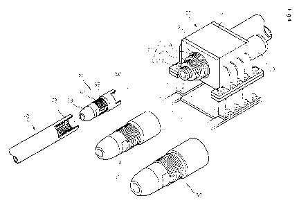
FIG. 3 is an exploded perspective view of a driving shaft according to an
embodiment of the present invention;
FIGS. 4 and 5 are perspective views of driving shafts according to another
embodiment of the present invention; and
FIG. 6 is a perspective view illustrating a state in which a driving shaft and
a unit rod are engaged with each other.
Best Mode for Carrying Out the Invention
Hereinafter, embodiments of the present invention will be described in
5
CA 02811779 2013-03-19
detail with reference to the accompanying drawings.
The drilling apparatus according to the present invention facilitates
engagement between a unit rod and a driving shaft of the head when the ground
hole is excavated, and en exemplary embodiment of the drilling apparatus is
shown in FIGS. 1 to 5.
Referring to FIGS. 1 to 5, the drilling apparatus 100 having a head includes
a lead 20 supported by a main body 10, a driving shaft 40 slidably installed
in the
lead 20 and connected to the topmost unit rod among the unit rods 70 connected
to each other for drilling work, a head 30 having an actuator (not shown) for
driving
the driving shaft 40, and a support pipe 200 installed on the ground for
preventing
earth and sand around a hole excavated by the lead from collapsing.
The head 30 slidably installed along the lead 20 and is configured to
elevate by a separate driver (although not shown, the driver including
sprockets
installed at top and bottom portions of the lead 20, a chain locked on the
sprockets
and having one side fixed to the head 30, and a hydraulic motor driving one of
the
sprockets). As shown in FIG. 2, a hydraulic motor 33 for driving the driving
shaft 40
rotatably supported by the bearing 32 is installed in a main body 31 of the
head 30.
The hydraulic motor 33 receives hydraulic oil by a hydraulic supply system
installed
in the main body 10 to then be driven.
As shown in FIGS. 2 and 3, the driving shaft 40 includes a screw coupling
part 41 and a screw coupling inducing part 42. The screw coupling part 41 is
formed on the outer circumferential surface of the driving shaft 40 and is
screw-
6
CA 02811779 2013-03-19
coupled to an end of the unit rod 70 for performing a drilling work. The screw
coupling inducing part 42 is formed at a front end of the screw coupling part
41 to
smoothly achieve screw coupling between the driving shaft 40 and a rod screw
coupling part 73 formed at a hollow part 70a at the end of the unit rod 70. A
The stopper 43 may include a protrusion formed on the outer
The hollow part 40a is formed at the driving shaft 40 in a lengthwise
direction. The screw coupling inducing part 42 may be tapered upwardly from
its
end. That is to say, a diameter of an end of the screw coupling induction part
42 is
FIG. 4 illustrates a head driving shaft of a drilling apparatus according to
another embodiment of the present invention.
7
CA 02811779 2013-03-19
Referring to FIG. 4, a head driving shaft 50 is supported on the head body
31 by a bearing 32 to be rotatably installed, and includes a first driving
shaft 51
formed at an end exposed to a bottom end of the head body 31 and a second
driving shaft 55 combined with the first driving shaft 51.
The first driving shaft 51 may include stepped coupling parts 51a, 51b and
51c having different diameters. Screws for being coupled to the second driving
shaft 55 are formed on the outer circumferential surfaces of the coupling
parts 51a,
51b and 51c.
The second driving shaft 55 may include a plurality of second driving shafts
having different diameters (corresponding to diameters of unit rods) to be
engaged
with the coupling parts 51a, 51b and 51c of the first driving shaft 51. The
second
driving shafts 55 having different diameters are provided for the purpose of
being
compatibly used when the unit rods for performing a drilling work have
different
diameters.
The second driving shaft 55 may include a coupling screw part 56, a screw
coupling part 57 and a screw coupling inducing part 58. The coupling screw
part 56
is formed on the inner circumferential surface of the second driving shaft 55
to be
coaxially coupled to the first driving shaft 51, the screw coupling part 57 is
formed
on the outer circumferential surface of the second driving shaft 55 to be
screw-
coupled to the rod screw coupling part 73 of the unit rod 70, and the screw
coupling inducing part 58 extends from the screw coupling part 57. As
described
above, the screw coupling inducing part 58 is tapered such that its diameter
8
CA 02811779 2013-03-19
gradually decreases from the screw coupling part 57 to its end. The end of the
screw coupling induction part 58 may be spherical to facilitate insertion of
the
hollow part 70a of the unit rod 70 into the screw coupling induction part 58.
A
hollow part 40a is formed in a lengthwise direction of the first and second
driving
shafts 51 and 55.
As shown in FIG. 5, the first and second driving shafts 51 and 55 may be
coupled to the first and second driving shafts 51 and 55 by flange parts 61
and 62.
A stopper 59 may be installed in the second driving shaft 55 to prevent the
unit rod 70 coupled to the second driving shaft 55 and performing a drilling
work
from elevating while rotating. A position adjusting unit (not shown) may
further be
provided at an upper portion of the stopper 59 to hold the support pipe 200
inserted
into an excavated portion for preventing earth and sand existing around the
excavated portion from collapsing. The position adjusting unit is tapered such
that
its upper side has a larger diameter than the support pipe 200.
The aforementioned drilling apparatus operates as follows.
As shown in FIGS. 1 and 6, in order to excavate an underground hole
using the drilling apparatus according to the present invention, the drilling
apparatus is positioned at a portion where the ground hole is to be formed,
and the
lead 20 is vertically positioned on the portion where the ground hole is to be
formed.
In such a state, the head 30 is positioned on the lead 20 and the unit rod 70
is then
connected to the driving shaft 40. An air hammer or a water hammer 80 for
performing a drilling work is installed at a bottom end of the unit rod 70.
9
CA 02811779 2013-03-19
The unit rod 70 and the driving shaft 40 are engaged with each other such
that the unit rod 70 is suspended using a crane (not shown), the screw
coupling
induction part 42 of the driving shaft 40 is inserted into the hollow part 70a
of the
unit rod 70, and the driving shaft 40 is rotated while moving the unit rod 70
and the
driving shaft 40 with respect to each other. In such a manner, in a state in
which
the screw coupling induction part 42 extending from the screw coupling part 41
of
the driving shaft 40 is inserted into the hollow part 70a of the unit rod 70,
the screw
coupling part 41 is guided to the rod screw coupling part 73 of the unit rod
70,
thereby facilitating engagement of the unit rod 70 and the driving shaft 40,
which
will now be described in more detail. Since the screw coupling induction part
42
provided at the driving shaft 40 has a diameter gradually decreasing from the
screw coupling part 41, even if the unit rod 70 and the driving shaft 40 are
not
aligned in line, the screw coupling induction part 42 can be easily inserted
into the
hollow part 70a of the unit rod 70.
Therefore, the problem associated with the conventional drilling apparatus,
that is, the necessity for making the end of the unit rod 70 and the driving
shaft 40
coincide with each other by an operator's manual work, can be solved. In
particular,
when the unit rod 70 has a small diameter and a small thickness, engagement of
the unit rod 70 and the driving shaft 40 can be smoothly achieved by being
guided
by the screw coupling induction part 42.
The above-described operation is achieved in the same manner as in
engagement of the second driving shafts 55 and the unit rod 70. In particular,
as
CA 02811779 2013-03-19
shown in FIG. 4, the coupling parts 51a, 51b and 51c formed in multiple-steps
are
provided in the first driving shaft 51, and the second driving shafts 55
suited to
diameters of the respective coupling parts 51a, 51b and 51c are provided,
thereby
allowing the second driving shafts 55 to be compatibly used according to the
diameters of the unit rods for performing a drilling work.
Meanwhile, the stopper 43 for preventing the unit rod 70 from elevating
due to a rotational force of the driving shaft 40 when the unit rod 70 is
screw-
coupled is provided at the driving shaft 40. Thus, even if a rotational load
is applied
to the unit rod 70 during a drilling work, it is possible to prevent the unit
rod 70 from
elevating along the screw coupling part 41 of the driving shaft 40. It is also
possible
to prevent the unit rod 70 screw-coupled to the screw coupling part 41 from
being
damaged due to the rotational load applied thereto while rotating. That is to
say,
the unit rod 70 can be prevented from being damaged, which may be caused when
the unit rod 70 elevates to a portion of the driving shaft 40 without screws
due to
the rotational load.
In addition, the position adjusting unit for balancing the support pipe 200
installed for drilling soft ground is further provided at the driving shaft
40. When the
head 30 is lowered, the position adjusting unit is inserted into the support
pipe 200,
thereby aligning centers of the support pipe 200 and the driving shaft 40.
Therefore,
it is possible to prevent the center of the support pipe 2000 from deviating
from the
center of the unit rod 70 while the drilling work is performed.
Although exemplary embodiments of the present invention have been
11
CA 02811779 2013-03-19
described in detail hereinabove, it should be understood that many variations
and
modifications of the basic inventive concept herein described, which may
appear to
those skilled in the art, will still fall within the spirit and scope of the
exemplary
embodiments of the present invention as defined by the appended claims.
12
CA 02811779 2013-03-19
4. A drilling apparatus having a head, comprising:
a main body;
a lead supported by the main body of the drilling apparatus;
a driving shaft slidably installed in the lead and having a unit rod connected
thereto for performing a drilling work; and
a head having an actuator for driving the driving shaft,
wherein the driving shaft includes a first driving shaft supported on the
head body by a bearing and exposed to a bottom end of the head body, and a
second driving shaft having a screw coupling part screw-coupled coaxially with
the
first driving shaft and screw-coupled with an end of the unit rod for
performing the
drilling work, and a screw coupling inducing part formed at a front end of the
screw
coupling part to induce screw coupling between the driving shaft and a rod
screw
coupling part formed at a hollow part formed at the end of the unit rod.
5. The drilling apparatus of claim 4, wherein the first driving shaft includes
stepped coupling parts having different diameters, and a plurality of second
driving
shafts having different diameters to be selectively coupled to the coupling
parts of
the first driving shaft.
14