Note : Les descriptions sont présentées dans la langue officielle dans laquelle elles ont été soumises.
CA 02811976 2013-01-11
WO 2012/009219 PCT/US2011/043345
TITLE: MANHOLE LINER AND METHOD OF USING THE SAME
FIELD OF THE INVENTION
The present invention generally relates to a method and means of repairing a
manhole. More particularly, but not exclusively, the invention relates to a
method and
assembly for lining a manhole wall.
BACKGROUND OF THE INVENTION
Conventional manholes include a lower or bottom pad, a barrel having a
relatively
constant diameter adjacent the pad, a concentric or eccentric cone extending
upwardly from
the barrel, one or more adjusting rings to adjust the overall height of the
manhole, and a
casting frame on top of the adjusting rings to support a lid at an elevation
substantially
level with the surrounding pavement. The casting frame is preferably sealed to
the
uppermost adjusting ring to preclude or minimize water flow into the manhole.
One problem with existing manholes is that many were made long ago, and then
oftentimes were made of brick. Due to the old age of the manholes, as well as
the
materials used to make them, many manholes have begun to deteriorate or have
damaged
areas. The damaged areas create weak spots, which may allow water to
infiltrate the sewer
system and also lead to the eventual collapse of the manhole.
Methods exist for repairing the walls of manholes. One such method involves
the
use of a cured-in-place (CIP) liner with a polymer coating on its interior
surface and a
bladder to repair the manhole wall. The liner and bladder are placed in the
manhole, and
the bladder is expanded to press the liner against the manhole wall. The liner
is
impregnated with a resin and applied to the wall to create a new interior wall
of the
manhole. One problem with existing methods is the size of the liner used to
line the wall
of the manhole. The methods call for the use of a CIP liner and bladder having
a diameter
approximately equal to the smallest diameter of the manhole, with the liner
being capable
of stretching circumferentially to press against the manhole wall so to
prevent the liner
from wrinkling. However, some manholes require that the liner stretch up to
and
1
CA 02811976 2013-01-11
WO 2012/009219 PCT/US2011/043345
exceeding 150 % of its unstretched diameter. This can cause the liners to rip,
tear or be too
thin, leaving the manhole wall not fully repaired.
Additionally, because the liners include an interior coating impervious to a
resinous
material, the liners cannot fold over themselves or bunch up because the liner
wall would
be formed with intermediate layers of material impervious to resin causing the
liner to not
be homogeneous across its thickness.
Accordingly, there is a need in the art for an improved method and means that
overcomes the problem of a liner tearing while stretching circumferentially to
press against
the wall of a manhole.
BRIEF SUMMARY OF THE INVENTION
It is therefore a principal object, feature, or advantage of the present
invention to
provide an improved method and means for lining a manhole which improves over
or
solves the deficiencies in the art.
Another object, feature, or advantage of the present invention is to provide
an
improved method and means for lining a manhole wall that allows a liner to
fold over itself
and to bunch up while still producing a smooth interior wall.
Another object, feature, or advantage of the present invention is to provide
an
improved method and means for lining a manhole wall wherein the diameter of
the liner is
sized to be larger than the smallest diameter of the manhole.
Another object, feature, or advantage of the present invention is to provide
an
improved method and means for lining a manhole wall wherein the diameter of
the liner is
sized to be substantially equal to a largest diameter of the manhole.
Another object, feature, or advantage of the present invention is to provide
an
improved method and means for lining a manhole that uses a liner to transport
a resinous
material capable of curing and hardening into a manhole.
Another object, feature, or advantage of the present invention is to provide
an
improved method and means for lining a manhole that uses a bladder capable of
stretching
circumferentially to press the liner against the wall of the manhole.
2
CA 02811976 2013-01-11
WO 2012/009219 PCT/US2011/043345
Another object, feature, or advantage of the present invention is to provide
an
improved method and means for lining a manhole that uses a liner for
containing a resinous
material capable of curing and hardening.
Another object, feature, or advantage of the present invention is to provide
an
improved method and means for lining a manhole that can be used in manholes
having
varying diameters along the height of the manhole.
These and/or other objects, features, and advantages of the present invention
will be
apparent to those skilled in the art. The present invention is not to be
limited to or by these
objects, features and advantages, and no single embodiment need exhibit every
object,
feature, and advantage.
According to one aspect of the present invention, a method of lining a manhole
having varying diameters along its height is provided. The method includes
taking a
manhole liner having a tubular shape and an unstretched diameter larger than a
smallest
diameter of the manhole. The liner is impregnated with a resinous material
capable of
curing and hardening. The liner is positioned in the manhole, and a bladder is
inserted into
the liner. The bladder is then expanded to press the liner against the wall of
the manhole,
with the liner folding on itself along a portion of the liner. The resinous
material is allowed
to cure and harden to produce a smooth finished surface, including along the
portion of the
liner folded on itself. Finally, the bladder is removed from the manhole.
According to another aspect of the present invention, a method of lining a
manhole
having varying diameters along the height of the manhole and having a largest
diameter
near the bottom of the manhole and a smallest diameter near the top of the
manhole is
provided. The method includes taking a manhole liner having a diameter
substantially
equal to the largest diameter of the manhole. The liner is impregnated with a
resinous
material capable of curing and hardening, and then positioned in the manhole.
An
inflatable bladder capable of stretching circumferentially is inserted into
the liner. Next,
the bladder is inflated to circumferentially stretch the bladder to press the
manhole liner
into contact with the wall of the manhole. The liner is folded over itself
along an upper
portion of the manhole. The resinous material is allowed to cure and harden
against a
substantially smooth surface of the bladder, and then the bladder is removed
from the
manhole.
3
CA 02811976 2013-01-11
WO 2012/009219 PCT/US2011/043345
According to yet another aspect of the present invention, a liner assembly for
lining
a manhole having varying diameters along the height of the manhole, with the
largest
diameter near the bottom of the manhole and the smallest diameter near the top
of the
manhole, is provided. The liner assembly includes a bladder and a manhole
liner. The
bladder comprises a first end, and opposite second end, and a bladder body
there between,
wherein the bladder body has a diameter smaller than or equal to the smallest
diameter of
the manhole. The bladder is also capable of stretching circumferentially. The
manhole
liner comprises a manhole liner body along its height, with the manhole liner
body having a
diameter substantially equal to the largest diameter of the manhole.
Additionally, the
manhole liner is impregnated with a resinous material capable of curing and
hardening.
BRIEF DESCRIPTION OF THE DRAWINGS
Figure 1 is a sectional view of an exemplary structure of a manhole.
Figure 2 is a sectional view of the liner assembly of the present invention
positioned in a manhole.
Figure 3 is a top sectional view of the manhole of Figure 2 according to line
3-3 of
Figure 2.
Figure 4 is a view similar to Figure 2 showing the bladder fully inflated in
the
manhole.
Figure 5 is a sectional view according to line 5-5 of Figure 4.
Figure 6 is a sectional view of the repaired manhole after the bladder has
been
removed.
Figure 7 is a sectional view according to line 7-7 of Figure 6.
DETAILED DESCRIPTION OF THE PREFERRED EMBODIMENTS
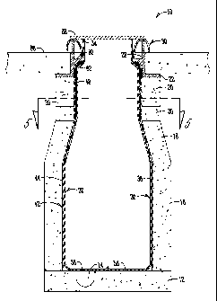
Figure 1 is a sectional view of an exemplary structure of a manhole 10. The
manhole 10 includes a bottom floor 12, a barrel 16 above the bottom floor 12,
a cone 18
supported by the barrel 16, and a plurality of adjusting rings 20 supported by
the cone 18.
A casting frame 22 resides upon the upper most ring 20 and supports a lid 26.
The casting
22 is normally sealed to the top ring 20. It is understood that one or more
rings 20 may be
used to adjust the height of the manhole 10 such that the lid 26 is
substantially at the level
4
CA 02811976 2013-01-11
WO 2012/009219 PCT/US2011/043345
of the pavement 66 surrounding the manhole 10. Also, while Figure 1 shows the
cone 18
to have a concentric shape, it is understood that an eccentric cone can be
utilized such that
the manhole 10 has an asymmetrical cross-sectional appearance. Figure 1 also
shows an
optional run through 14 in the bottom floor 12. While each manhole generally
has unique
size and shape, it is generally understood that the basic construction of the
manhole 10 is
similar in all manholes. Although manholes comprise varying diameters D1, D2,
D3, and
D4 along the height of the manholes, the manholes generally are narrower at
the top
section, or chimney, than at the bottom section. Additionally, bricks 72
generally form the
wall 24 of manholes.
Figure 2 is a sectional view of the liner assembly 30 of the present invention
positioned in a manhole 10. The liner assembly 30 includes a bladder 32, a
manhole liner
42, and a base 68. The bladder 32 comprises a first end 34 attached to the
base 68 near the
opening 28 of the manhole 10, a second end 36 positioned at the bottom 58 of
the manhole,
and a bladder body 38 there between. The first end 34 of the bladder 32 may be
attached to
the base 68 outside of the manhole 10 as well. The diameter 40 of the bladder
32 is
preferably less than or equal to the smallest diameter D1 of the manhole 10.
However, the
bladder body 38 is stretchable such that it is able to press against a wall 24
of the manhole
10 when expanded. The manhole liner 42 is attached at the opening 28 of the
manhole,
and comprises a manhole liner body 44 that at least partially surrounds the
bladder body 38
in the manhole 10.
The manhole liner body 44 is comprised of lining material substantially free
of
coating or intermediate layers of material impervious to the resinous material
48. The
resinous material 48 may be a thermoset resin, which saturates the liner and
cures and
hardens quicker in the presence of heat. However, it should be appreciated
that other
resinous materials may be used, on the condition that they are able to cure
and harden. The
manhole liner 42 is essentially a transport device, such that the resinous
material 48 forms
the structural properties of the liner when cured.
The diameter 46 of the manhole liner 42 in one preferred form is sized
substantially
equal to the largest diameter D1 of the manhole 10. Therefore, the manhole
liner 42 does
not need to be stretchable. After the manhole liner 42 has been impregnated
with a
resinous material 48, the manhole liner 42 is positioned in the manhole 10.
The bladder 32
5
CA 02811976 2013-01-11
WO 2012/009219 PCT/US2011/043345
is then inserted into the manhole liner 42. Figure 3 is a top sectional view
of the manhole
of Figure 2 according to line 3-3 of Figure 2. Figure 3 shows the bladder 32
and the
manhole liner 42 positioned in the manhole 10. As is seen in Figure 3, the
diameter 40 of
the bladder 32 is less than the diameter 46 of the manhole liner 42. As is
also shown in
5 Figure 3, the original diameter 46 of the manhole liner 42 is
substantially greater than the
diameter D3 of the manhole 10 at the adjusting rings 20. Because the diameter
46 of the
manhole liner 42 is greater than the diameter D3 of the adjusting rings 20,
the manhole
liner will fold over itself and bunch up to fit within the top section 60 of
the manhole 10.
In another preferred form, the diameter 46 of the manhole liner 42 is sized
larger
10 than the smallest diameter of the manhole 10. Here, the manhole liner
will again fold over
on itself and bunch up to fit the smaller diameter portions of the manhole 10.
Figure 4 is a sectional view similar to Figure 2 showing bladder 32 fully
inflated in
the manhole 10. The bladder 32 is inflated with fluid pressure (not shown),
such as air,
introduced to the cavity 70 of the bladder body 38. The increased pressure
causes the
stretchable bladder body 38 to expand circumferentially towards the wall 24 of
the
manhole 10. The expanded bladder will press the manhole liner 42 against the
wall 24 of
the manhole 10. This will create a layer 64 of resinous material 48 between
the manhole
liner 42 and the bladder body 38. Because the bladder 32 has stretched
circumferentially
against the manhole liner 32, the bladder body 38 will have a smooth surface
abutting the
layer 64 of resinous material 48. This ensures that the resulting manhole wall
24 will be
smooth.
Figure 5 shows a top sectional view of the manhole 10 of Figure 4 according to
the
line 5-5 of Figure 4. Figure 5 is a sectional view of the manhole 10 near the
top section 60
of the manhole 10, where the diameter D3 of the manhole is substantially
smaller than the
diameter D1 of the bottom 58 of the manhole 10. Because the manhole liner 42
has been
sized substantially equal to the diameter D1 of the larger section of the
manhole 10, there
will be excess manhole liner body 44 at this upper section. The excess manhole
liner body
44 will fold over itself and bunch up to create folds 52 in the liner.
However, because the
manhole liner 42 does not contain a resin impermeable coating, the folds 52
will compress
and resinous material 48 will form a manhole liner 42 in the same way as in
the bottom
section, where the manhole liner 42 is a single layer. The compression creates
a layer 62 of
6
CA 02811976 2013-01-11
WO 2012/009219 PCT/US2011/043345
resinous material 48 between the manhole liner 42 and the bladder 32. The
thickness of
the layer 62 of resinous material may vary according to the number of folds 52
or bunches
in the manhole liner 42. However, because the bladder 32 was stretched to
press the
manhole liner 42 against the wall 24 of the manhole 10, the bladder 32 will
have a smooth
surface 56 pressed against the varying layers of resinous material 48. This
will result in the
resinous material having a smooth interior surface. Because the folds 52
contain two or
more layers of manhole liner 42, the resinous material 48 will cure and harden
to produce a
thicker wall 24 of the manhole 10 at the top section 60 of the manhole.
However, because
the top section 60, including the cone 18 and adjusting rings 20 (the
chimney), of the
manhole 10 undergoes the most stress and usually contains the most damage, the
resulting
thicker wall 24 will be stronger to help resist cracking due to freezing and
thawing.
Figure 6 is a sectional view of the manhole 10 after the resinous material 48
has
cured and hardened and the bladder 32 has been removed from the manhole 10.
The
bladder 32 may be removed by deflating the fluid from the cavity 70, and then
by pulling a
rope (not shown) connected to the second end 36 of the bladder 32. Pulling the
bladder 32
out by the bottom first causes the bladder 32 to peel away from the cured
resinous material
48. Although peeling the bladder 32 requires the least amount of effort, it
should be
appreciated that the bladder 32 may also be pulled straight out of the manhole
10 from the
first end 34 of the bladder 32 as well. After the manhole lid 26 is replaced
on the casting
frame 22 of the manhole, what remains is a manhole 10 having a repaired and
structurally
renewed wall 24. As is shown in Figure 6, the manhole liner 42 has compressed
the
impregnated resinous material 48 from the manhole liner body 44, creating a
cured
resinous material layer 62 around the interior periphery of the manhole 10. As
stated
above, the layer 62 will be thicker in the top portion 60, or the chimney, of
the manhole 10
because the manhole liner will have folded over itself The thicker layer aids
the section
most affected by the elements, however. The folds 52 will occur in areas of
the manhole
10 having a diameter less than the largest diameter D1 of the manhole 10.
Figure 7 is a top sectional view of the manhole 10 of Figure 6 according to
the line
7-7 of Figure 6. Figure 7 shows that although the manhole liner 42 folded over
itself, the
manhole liner 42 was compressed against the smooth outer surface 56 of the
bladder 32,
such that the interior periphery of the resinous material 48 cured into a
smooth finish 50.
7
CA 02811976 2014-06-17
,
. .
At the upper section of the manhole, the folds 52 of the manhole liner 42 will
cause the cured
resinous layer 62 to be thicker than at the bottom of the manhole 10. However,
because the
bladder 32 is pressed against the manhole liner 42 with even pressure, the
layer 62 of resinous
material 48 will be substantially equal at a given height around the interior
of the manhole 10.
The resinous material 48 will migrate from the liner to fill low areas of the
liner, formed due to
the folds, to create a resinous surface that is smooth about the interior
periphery of the manhole
10. The smooth finish 50 of the cured resinous material 48 allows the manhole
to be used as it
had previously before it required repair.
The invention has been shown and described above with reference to preferred
embodiments, and it is understood that modifications, substitutions, and
additions may be made
which are within the intended scope of the invention. The invention is only to
be limited by
claims appended hereto.
8