Note : Les descriptions sont présentées dans la langue officielle dans laquelle elles ont été soumises.
CA 02812251 2013-03-21
WO 2012/051067 PCT/US2011/055375
READ HEAD DEVICE WITH SLOT CONFIGURED TO REDUCE TORQUE
BACKGROUND OF THE INVENTION
[0001] Plastic cards having a magnetic stripe embedded on one side of the card
are
prevalent in everyday commerce. These cards are used in various transactions
such as to
pay for purchases by using a credit card, a debit card, or a gasoline charge
card. A charge
card or a debit card may also be used to transact business with a bank through
use of an
automated teller machine (ATM). The magnetic stripe card is capable of storing
data by
modifying the magnetism of magnetic particles embedded in the stripe. The data
stored on
the magnetic stripe may be sensed or read by swiping the stripe past a read
head. The
analog waveform obtained by sensing the magnetic stripe must undergo a process
known
as decoding to obtain the digital information stored in the magnetic stripe of
the card.
[0002] Currently, there are hundreds of magnetic stripe readers/swipers on the
market, all
of them are at least as long as the credit card itself. These existing
readers/swipers can be
classified as either platform card readers or plunge card readers. Platform
card readers are
traditional card swipers with single rails, which allow a card to be held
against the base of
the reader by the user and moved across the read head of the reader. Plunge
swipers
guide a card by two sets of rails and a backstop. Once the user has inserted
the card
against the backstop, the card is read as it is removed from the plunge
swipers. Plunge
swipers are common on ATMs and other self-pay devices because they are less
prone to
hacking.
[0003] Magnetic stripe cards having standard specifications can typically be
read by point-
of-sale devices at a merchant's location. When the card is swiped through an
electronic
card reader, such as a platform card reader, at the checkout counter at a
merchant's store,
the reader will usually use its built-in modem to dial the number of a company
that handles
credit authentication requests. Once the account is verified and an approval
signal will be
sent back to the merchant to complete a transaction.
[0004] Although magnetic stripe cards are universally used by merchants, there
is no way
for an individual to take advantage of the card to receive a payment from
another individual
(who is not a merchant) by swiping the card through a simple reader attached
to his/her
mobile device. For a non-limiting example, one person may owe another person
money for
a debt, and the conventional way to pay the debt is to provide cash or a
check. It would be
convenient to be able to use a credit card or a debit card to pay off the
debt. In addition, it is
advantageous for an individual to make payment to another individual or
merchant by
swiping his magnetic stripe card through a reader connected to a mobile
device.
1
CA 02812251 2015-07-27
52962-12
[0005] The foregoing examples of the related art and limitations related
therewith are
intended to be illustrative and not exclusive. Other limitations of the
related art will
become apparent upon a reading of the specification and a study of the
drawings.
SUMMARY OF THE INVENTION
[0006] An object of some embodiments of the present invention is to provide
systems and methods for payment by mobile devices.
[0007] Another object of some embodiments of the present invention is to
provide
systems and methods for payment using a portable electronic device, such
devices
include software, firmware, hardware, or a combination thereof that is capable
of at
least receiving the signal, decoding if needed, exchanging information with a
transaction server to verify the buyer and/or seller's account information,
conducting
the transaction.
[0008] A further object of some embodiments of the present invention is to
provide a
read head system, and its methods of use, that includes a slot oriented and
sized to
reduce torque applied on the read head.
[0009] In one embodiment of the present invention, there is provided a read
head
system that has a housing and a read positioned in the housing with a slot for
swiping
a magnetic stripe of a financial transaction card with the slot utilized to
enable a
financial transaction between a buyer and seller. The read head reads data on
the
magnetic stripe and produces a signal indicative of data stored on the
magnetic
stripe. The read head includes an output jack configured to be coupled to at
least one
of a audio jack or microphone port of a mobile device. The read head provides
the
signal to the mobile device. The slot is oriented and sized to reduce torque
applied on
the read head as the financial transaction card is swiped through slot in
order to
maintain accuracy and reliability of the data read by the read head. Decoding
of the
signal is performed in the mobile device. The decoding includes determining
pulses in
the signal and converting at least some of the pulses to characters.
2
CA 02812251 2015-07-27
52962-12
[0010] In another embodiment of the present invention, a method is provided
for
conducting a financial transaction with a financial transaction card. A read
head is
provided that is positioned in a housing. The read head includes an output
jack that is
configured to physically connect the read head with a microphone port of a
mobile
device. The slot is oriented and sized to reduce torque applied on the read
head
when the financial transaction card is swiped through slot in order to
maintain
accuracy and reliability of the data read by the read head. In response to
swiping the
card through the slot, a signal is produced indicative of data stored on the
magnetic
stripe. The signal is sent from the read head via the output jack of the read
head to
the mobile device. The signal is decoded at the mobile device.
[0010a] In another embodiment of the present invention, there is provided a
card
reader, comprising: a housing; a read head positioned in the housing and
having a
slot for swiping a magnetic stripe of a financial transaction card with the
slot utilized to
enable a financial transaction between a buyer and seller, the slot having a
predetermined width for receiving the financial transaction card, the slot
being
positioned off-center a width of the housing, the read head configured to read
data on
the magnetic stripe and produce a signal indicative of data stored on the
magnetic
stripe; an output jack configured to be coupled and de-coupled to at least one
of an
audio jack or microphone port of a mobile device, the output jack configured
to
provide the signal to the mobile device; one or more supports that suspend the
read
head in the housing; and a spring in the housing that provides an ability of
the read
head to swivel in the housing while maintaining a contact pressure of the slot
to track
the stripe of the card being swiped, the spring being connected to at least
one of the
one or more supports in the housing to enable the swivel without causing the
one or
more supports to move, whereby, in response to receiving a swipe of the
financial
transaction card through the slot, an amount of torque applied between the
read head
and the output jack is reduced based at least in part on the predetermined
width of
the slot, the slot being positioned off-center the width of the housing, and
the spring
being connected to the at least one of the one or more supports.
2a
CA 02812251 2013-03-21
WO 2012/051067 PCT/US2011/055375
BRIEF DESCRIPTION OF THE DRAWINGS
[0011] FIG. 1 depicts an example of a system diagram to support financial
transaction
between a payer and a payee through a miniaturized card reader connected to a
mobile
device.
[0012] FIG. 2 depicts an example of an external structural diagram of a
miniaturized card
reader.
[0013] FIGs. 3(a)-(b) depict examples of actual card reader with miniaturized
design.
[0014] FIGs. 4(a)-(b) depict examples of alignment between read head of the
card reader
and magnetic stripe of card being swiped.
[0015] FIG. 5 depicts an example of a TRS connector as a part of card reader.
[0016] FIGs. 6(a)-(c) depict examples of internal structures of a miniaturized
card reader.
[0017] FIGs. 7(a)-(b) depict examples of waveforms of data read from one track
of the
magnetic stripe by read head when the card is swiped through the slot of the
card reader in
the forward and reverse directions, respectively.
[0018] FIG. 8 depicts a flowchart of an example of a process to support
swiping of a card
with a magnetic stripe through a miniaturized portable card reader.
[0019] FIG. 9 depicts an example of schematic diagram of passive ID circuitry
embedded in
the card reader.
[0020] FIG. 10 depicts an example of schematic diagram that contains
additional
components of passive ID circuitry 22 that contribute to the user experience.
[0021] FIG. 11 depicts an example of an implementation for passive ID
circuitry 22 depicted
in FIG. 10.
[0022] FIG. 12 depicts a flowchart of an example of a process to deliver the
unique ID to
mobile device via the passive ID circuitry.
[0023] FIG. 13 depicts an example of additional encryption and/or decryption
systems
included in the passive ID circuitry for encrypting and decrypting of unique
ID of card reader.
[0024] FIG. 14 depicts a flowchart of an example of a process to support
decoding of
incoming signals from swiping of a card with a magnetic stripe through a
miniaturized
portable card reader.
[0025] FIG. 15 depicts a flowchart of an example of a process to support
financial
transaction between a payer and a payee through a miniaturized card reader
connected to a
mobile device.
[0026] FIGs. 16(a)-(f) depict screenshots of an example of a financial
transaction between a
purchaser and a merchant through a miniaturized card reader connected to a
mobile device.
3
CA 02812251 2013-03-21
WO 2012/051067 PCT/US2011/055375
[0027] FIG. 17 illustrates an integrated read head/mobile device embodiment of
the present
invention.
DETAILED DESCRIPTION OF THE PREFERRED EMBODIMENTS
[0028] The approach is illustrated by way of example and not by way of
limitation in the
figures of the accompanying drawings in which like references indicate similar
elements. It
should be noted that references to "an" or "one" or "some" embodiment(s) in
this disclosure
are not necessarily to the same embodiment, and such references mean at least
one.
[0029] A new approach is proposed that contemplates systems and methods to
enable an
individual to complete a financial transaction by swiping a magnetic stripe
card through a
card reader connected to a mobile device. It will be appreciated that the
systems and
methods of the present invention can be used with financial transactions cards
characterized as: (i) allowing a user to choose to pay with reward points or
credit, (ii) one
that is a credit and a debit card, (iii) having fraud protection built into
the card, (iv) having an
integrated chip instead of a magnetic strip and the like. In the embodiment of
card with an
integrated chip, the card has electrical connectors which when fed a current
respond with a
signal indicative of information stored on the card. A read head is not used
with this type of
card.
[0030] Here, the financial transaction can be any transaction that involves
receiving or
sending payment from one person to another. The magnetic stripe card can be
but is not
limited to a credit card, a debit card, or other types of payment
authenticating pieces
capable of carrying out the financial transaction. The size of the card reader
is miniaturized
to be portable for connection with the mobile device. The card reader is
configured to
reliably read data encoded in a magnetic strip of the card with minimum error
in a single
swipe and provide a signal that corresponds to the data read to the mobile
device, which
then decodes the incoming signal from the card reader and acts as a point-of-
sale device to
complete the financial transaction. Such an approach enables a person to
become either a
micro-merchant (payee) or a buyer/customer (payer) without having to purchase
expensive
card reader devices or software.
[0031] FIG. 1 depicts an example of a system diagram to support financial
transaction
between a payer and a payee through a miniaturized card reader connected to a
mobile
device. Although the diagrams depict components as functionally separate, such
depiction
is merely for illustrative purposes. It will be apparent that the components
portrayed in this
figure can be arbitrarily combined or divided into separate software, firmware
and/or
hardware components. Furthermore, it will also be apparent that such
components,
4
CA 02812251 2013-03-21
WO 2012/051067 PCT/US2011/055375
regardless of how they are combined or divided, can execute on the same host
or multiple
hosts, and wherein multiple hosts can be connected by one or more networks.
[0032] In the example of FIG. 1, the system includes a mobile device 100, a
miniaturized
card reader 10 connected to mobile device 100, a decoding engine 110, a user
interaction
engine 120, and a transaction engine 130, all running on mobile device 100.
Additionally,
the system may also include one or more of user database 140, product or
service
database 150, and transaction database 160, all coupled to the transaction
engine 130.
[0033] As used herein, the term engine refers to software, firmware, hardware,
or other
component that is used to effectuate a purpose. The engine will typically
include software
instructions that are stored in non-volatile memory (also referred to as
secondary memory).
When the software instructions are executed, at least a subset of the software
instructions is
loaded into memory (also referred to as primary memory) by a processor. The
processor
then executes the software instructions in memory. The processor may be a
shared
processor, a dedicated processor, or a combination of shared or dedicated
processors. A
typical program will include calls to hardware components (such as I/O
devices), which
typically requires the execution of drivers. The drivers may or may not be
considered part of
the engine, but the distinction is not critical.
[0034] As used herein, the term database is used broadly to include any known
or
convenient means for storing data, whether centralized or distributed,
relational or
otherwise.
[0035] In the example of FIG. 1, mobile device 100 to which the portable card
reader 10 is
connected to can be but is not limited to, a cell phone, such as Apple's
iPhone, other
portable electronic devices, such as Apple's iPod Touches, Apple's iPads, and
mobile
devices based on Google's Android operating system, and any other portable
electronic
device that includes software, firmware, hardware, or a combination thereof
that is capable
of at least receiving the signal, decoding if needed, exchanging information
with a
transaction server to verify the buyer and/or seller's account information,
conducting the
transaction, and generating a receipt. Typical components of mobile device 100
may
include but are not limited to persistent memories like flash ROM, random
access memory
like SRAM, a camera, a battery, LCD driver, a display, a cellular antenna, a
speaker, a
Bluetooth circuit, and WIFI circuitry, where the persistent memory may contain
programs,
applications, and/or an operating system for the mobile device.
[0036] In one embodiment of the present invention a system is provided with
transaction
engine 130 running on mobile device 100. In response to a financial
transaction between a
buyer and a seller, the mobile device 100 accepts information selected
including but not
limited to information from financial transaction or information pertaining to
financial
CA 02812251 2013-03-21
WO 2012/051067 PCT/US2011/055375
transaction card used by the buyer in the transaction. Additionally, a
financial transaction
device can be utilized. Non-limiting examples of financial transaction devices
include but
are not limited to a, wristband, RFID chip, cell phone, biometric marker and
the like. At
least a portion of this information is communicated with a third party
financial institution or
payment network to authorize the transaction. The buyer receives confirmation
of the
payment. Payment confirmation can be in real time.
[0037] Payment confirmation can be made with a communication channel of the
buyer's
choice. As non-limiting examples, confirmation of payment can be an electronic
notification
in the form selected from at least one of, email, SMS message, tweet (message
delivered
via Twitter), instant message, communication within a social network and the
like.
[0038] In response to the transaction, a confirmation is made that the buyer
is authorized to
use the financial transaction card in order to prevent fraud. There can also
be a
confirmation that there are sufficient funds for the purchase made by the
buyer.
[0039] In one embodiment, it is determined that that the buyer, authorized to
use the
financial transaction card, is present with the seller at the time of the
financial transaction.
Miniaturized card reader
[0040] In the example of FIG. 1, miniaturized card reader 10 is configured to
read data
encoded in a magnetic strip of a card being swiped by a buyer and send a
signal that
corresponds to the data read to mobile device 100 via a signal plug 18. This
signal is at
least partially if not fully decoded in the mobile device 100.
[0041] The size of card reader 10 is miniaturized to be portable for
connection with mobile
device 100. For a non-limiting example, the size of card reader 10 can be
miniaturized to
an overall length of less than 1.5". In addition, the miniaturized card reader
10 is also
designed to reliably read the card with minimum error via a single swipe by
counteracting
vendor specific filtering done by mobile device 100. Note that this broad
overview is meant
to be non-limiting as components to this process are represented in different
embodiments.
For instance the decoding engine 110 can be embedded in the card reader 10 as
shown in
FIG. 13 as the decoding system 42.FIG. 2 depicts an example of an external
structural
diagram of miniaturized card reader 10. Although the diagrams depict
components as
functionally separate, such depiction is merely for illustrative purposes. It
will be apparent
that the components portrayed in this figure can be arbitrarily combined or
divided into
separate software, firmware and/or hardware components.
[0042] In the example of FIG. 2, miniaturized card reader 10 is shown to
comprise at least a
housing 12 having a slot 14, a read head 16 embedded on a wall of slot 14, a
signal plug 18
extending out from the housing 12, and an optional passive ID circuit 22.
6
CA 02812251 2013-03-21
WO 2012/051067 PCT/US2011/055375
[0043] FIG. 3(a) depicts an example of an actual card reader with miniaturized
design and
FIG. 3(b) depicts other examples of miniaturized card reader with width around
0.5".
[0044] The card reader 10 includes the slot 14 and is miniaturized relative to
the size of the
mobile device 100. In some embodiments, the housing 12 is not included.
[0045] In one embodiment, the slot 14 is configured to maintain contact
between the read
head 16, and the magnetic stripe of the financial transaction card during a
swipe. The
signal is decoded in the mobile device 100. The decoding includes determining
pulses in
the signal and converting at least some of the pulses to characters. In one
embodiment,
the slot 14 has a width of no greater than 1 mm. The width of the slot 14 is
sufficient to
enable a successful swiping of the financial transaction card, while producing
the signal. It
is sized to enable the successful swipe without creating sufficient torque
between the signal
plug 18 or output jack and the read head 16 or at the mobile device 100 to
cause damage
due to excessive torque. If the slot 14 is too wide, then it is more difficult
to achieve a
successful swipe that produce the signal. If there is a miss, or insufficient
data is generated,
then the resulting signal is not competent. If the slot 14 is too narrow, then
the financial
transaction card can not be swiped. The size of the slot 14 is selected to
reduce torque as
discussed above. Additionally, in one embodiment, the output jack 18 is at
least partially if
not fully rotatable relative to the port it is coupled to in the mobile device
100. The decoding
includes error checking. In one embodiment, the decoding includes detecting
that data in
the signal is from the financial transaction card, seeing the beginning and
ending sentinels
and reconstructing data in the signal from a pattern of pulses.
[0046] In one embodiment of the present invention, the mobile device 100 has
an audio
input port and a line input port. In one embodiment, a sampling rate of the
signal at
the audio input port or a line input port of the mobile device is at least
15kHZ. In various
other embodiments, the sample rate of the signal at the audio input port or
line import port
can be, least 20 kHz; at least 25 kHz, at least 30 kHz, at least 35 kHz or at
least 40 kHz.
[0047] In one embodiment, the slot 14 is oriented and sized to reduce torque
applied on the
read head 10 when the financial transaction card is swiped through the slot 14
in order to
maintain accuracy and reliability of the data read by the read head 10.
[0048] In the example of FIG. 2, housing 12 of card reader 10 is designed to
be
asymmetrical with respect to slot 14, with texture such as logo on one side of
the housing
that can be felt and recognized by a user with a touch of a finger. For
correct swiping of the
card, the texture side of housing 12 should match with the texture (front)
side of the card, so
that a user can easily identify the right side of the reader to swipe the card
through slot 14
without actually looking at the reader or card. Even a blind person is able to
swipe the card
correctly by matching the texture side of the reader with the texture side of
the card.
7
CA 02812251 2013-03-21
WO 2012/051067 PCT/US2011/055375
[0049] In the example of FIG. 2, the slot 14 is wide enough and deep enough to
accept a
card having a magnetic stripe so that the stripe will fit within the slot 14.
More importantly,
the slot 14 is configured to reduce the torque applied on the reader 10 when
the card is
swiped through slot 14 in order to maintain accuracy and reliability of the
data read by read
head 16. Since the size of card reader 10 is miniaturized, slot 14 also has a
length that is
significantly less than the length of the card to be inserted into the slot
14.
[0050] To correctly read the data on the magnetic stripe of the card, the read
head 16 must
maintain contact with the stripe as the card moves past slot 14. If the card
rocks during the
swipe, the alignment of the head 12 with the stripe may be compromised. As the
length of
the slot 14, i.e., the card path through which the card swiped though slot 14,
is shortened,
rocking and head alignment may become significant issues. As shown in FIG.
4(a), if the
magnetic stripe card is swiped through without the base of the card resting
against the flat
bottom piece, the magnetic stripe will not align with the read head 16 when
the card is
swiped through slot 14 having a flat base 15.
[0051] In some embodiments, the base 15 of slot 14 can be changed from flat to
a curved
base with a radius in order to increase contact between the read head 16 and
the magnetic
stripe to address the rocking problem. As shown in FIG. 4(b), the read head 16
can
maintain contact with the magnetic stripe, even with some additional error due
to the
gradation of contact introduced by the curved base 15.
[0052] FIG. 5 depicts an example of signal plug 18 as part of card reader 10.
Here, signal
plug 18 can be but is not limited to a TRS (tip, ring, sleeve) connector also
known as an
audio plug, phone plug, plug plug, stereo plug, mini-plug, or a mini-stereo
audio connector.
The signal plug 18 may be formed of different sizes such as miniaturized
versions that are
3.5 mm or 2.5 mm.
[0053] In some embodiments, signal plug 18 may be retractable within the
housing 12. In
some embodiments, signal plug 18 is configured to extend beyond housing 12 of
the reader
in order to accommodate connection with mobile devices 100 having cases or
having a
recessed plug-in socket, wherein the socket can be but is not limited to a
microphone input
socket or a line in audio input of the mobile device.
[0054] In some embodiments, housing 12 of card reader 10 is made of non-
conductive
material such as plastic so that the reader will not interfere with the
function of mobile
device 100 it is connected with. Such choice of material is important since
the outer case of
certain mobile devices, such as iPhone 4, is conductive and serves as an
antenna for the
device, which function could potentially be interfered with if the metal case
of the device
gets in touch with the housing of a card reader made of conductive material.
8
CA 02812251 2013-03-21
WO 2012/051067 PCT/US2011/055375
[0055] FIG. 6(a) depicts an example of an internal structural diagram of a
miniaturized card
reader. Although the diagrams depict components as functionally separate, such
depiction
is merely for illustrative purposes. It will be apparent that the components
portrayed in this
figure can be arbitrarily combined or divided into separate software, firmware
and/or
hardware components.
[0056] In the example of FIG. 6(a), the internal structure inside housing 12
of card reader
is shown to comprise at least a read head 16 with embedded circuitry, and a
spring
structure 20 to support read head 16. FIG. 6(b) depicts an example of an
internal structure
an actual miniaturized card reader. FIG. 6(c) depicts an example of separated
components
of read head 16 and spring structure 20 used in the actual miniaturized card
reader.
[0057] In the example of FIGs. 6(a)-(c), read head 16, which for a non-
limiting example, can
be an inductive pickup head, detects and provides data stored in the magnetic
stripe of a
card to a connected mobile device 100. More specifically, as the magnetic
stripe of a card
is swiped through slot 14 and in contact with read head 16, the card reader
device 10 reads
one or more tracks of data or information stored in the magnetic stripe of the
card via the
detection circuitry embedded inside the read head. Here, data stored in the
magnetic stripe
may be in the form of magnetic transitions as described in the ISO 7811
standards. As the
card moves past the read head 16, magnetic transitions representing data
induce a voltage
or waveform in a coil (not shown) of read head 16 due to such relative
movement between
read head 16 and the stripe (called the Hall Effect), wherein a resistor (not
shown) inside
read head 16 sets the amplitude of the waveform. This waveform is sent via the
signal plug
18 into the socket which is registered by the microphone of the mobile device
100
connected with card reader 10.
[0058] In some embodiments, read head 16 in card reader is capable of reading
only one
track of data (either track 1 or 2, but not both) from the magnetic stripe in
order to reduce
the size and structural complexity of compact read head 16 as only one pin
needs to be
included in the read head. FIGs. 7(a)-(b) depict examples of waveforms of data
read from
track 1 (instead of both tracks 1 and 2 as by a traditional read head) of the
magnetic stripe
by read head 16 when the card is swiped through slot 14 in the forward and
reverse
directions, respectively.
[0059] In some embodiments, the size or thickness of the housing 12 of card
reader 10 is
configured to be narrow enough to accommodate only a single read head 16. Such
design
is intended to be tampering-proof so that even if the housing 12 is tampered
with, no
additional circuitry can be added to the card reader 10 and such tampering
will render the
card reader non-functional.
9
CA 02812251 2013-03-21
WO 2012/051067 PCT/US2011/055375
[0060] In the example of FIGs. 6(a)-(c), spring structure 20 is a flexible
spring mounting to
read head 16 without a screw, causing the read head to be suspended to housing
12 of
card reader 10. Here, spring 20 can either be connected to housing 12 via
screws or
welded to plastic housing 12 without using any screws. As the card moves past
the read-
head 16 on the miniaturized card reader, any card bending or misalignment may
cause the
read head to lose contact with the magnetic stripe. Spring 20 allows suspended
read head
16 to swivel while maintaining contact pressure to track the stripe of the
card being swiped.
Spring 20 is designed to be sufficiently small to fit within the miniaturized
card reader 10, yet
powerful enough to maintain good contact during the stripe. Unlike traditional
spring
structures, spring 20 positions the supports for read head 20 inside the
overall form of the
spring, which allows the spring to flex without having to make one support
moveable.
[0061] FIG. 8 depicts a flowchart of an example of a process to support
swiping of a card
with a magnetic stripe through a miniaturized portable card reader. Although
this figure
depicts functional steps in a particular order for purposes of illustration,
the process is not
limited to any particular order or arrangement of steps. One skilled in the
relevant art will
appreciate that the various steps portrayed in this figure could be omitted,
rearranged,
combined and/or adapted in various ways.
[0062] In the example of FIG. 8, the flowchart 800 starts at block 802 where a
miniaturized
card reader is structured to provide sufficient contact between a read head
and the
magnetic stripe during a swipe of a card. The flowchart 800 continues to block
804 where a
card with a magnetic stripe is swiped through a slot of the miniaturized card
reader. The
flowchart 800 continues to block 806 where the read head reliably reads data
stored in the
magnetic stripe and generates an analog signal or waveform indicative of data
stored in the
magnetic stripe. The flowchart 800 continues to block 808 where amplitude of
the
waveform is set by the circuitry inside the read head. The flowchart 800 ends
at block 810
where the set waveform is provided to a mobile device 100 connected with the
miniaturized
card reader via the signal plug 18.
Passive ID circuit
[0063] In some embodiments, housing 12 of card reader 10 may further
encapsulate a
passive ID circuitry 22 powered by the mobile device 100 through signal plug
18, wherein
passive ID circuitry 22 delivers an unique ID of the card reader to mobile
device 100 only
once upon the card reader being connected to (and powered up by) the mobile
device.
Although both are integrated in the same housing 12, passive ID circuitry 22
functions
independently and separately from read head 18 without interfering with the
read head's
card swiping functions described above.
CA 02812251 2013-03-21
WO 2012/051067 PCT/US2011/055375
[0064] FIG. 9 depicts an example of schematic diagram of passive ID circuitry
embedded in
the card reader. In the example of FIG. 9, passive ID circuitry 22 may
comprise at least five
main subsystem/components: unique ID storage 24, communication subsystem 26,
which
reads and transmits the unique ID from unique ID storage 24, power subsystem
28, which
provides power to enable communication with mobile device 100, a pathway
subsystem 30
to route signals to signal plug 18 through the circuitry, and a control unit
32, to orchestrate
the communication between different systems. All of these subsystems can be
implemented in hardware, software or a combination thereof. Communication
subsystem
26, power subsystem 28, and read head 16 share the same signal plug 18 for
connection
with the mobile device. The components portrayed in this figure can be
arbitrarily combined
or divided into separate software, firmware and/or hardware components.
[0065] In the example of FIG. 9, unique ID storage 24 is memory containing the
Unique ID
of the card reader. The unique ID storage 24 can be any persistent memory
containing
bytes that can be accessed by the communication subsystem 26.
[0066] In the example of FIG. 9, the power subsystem 28 comprises of a
modified charge
pump, which utilizes a digital circuit to artificially raise the voltage of a
power source to a
higher level. Normal charge pump operation requires large current which is
then fed into
several capacitors, and switching logic switches the capacitors between series
and parallel
configurations. In the example of FIG. 10, the power source is a bias voltage
provided by
the mobile device meant for detection of a connected component. It is
nominally 1.5V and
is supplied through a 2k0 resistor, resulting in a maximum current of 7501JA.
Details of how
the power subsystem 28 function is described in FIG. 11.
[0067] In standard operation the pathway subsystem 30 is configured to direct
the mobile
device's 100 bias voltage to the power subsystem 28. After the power subsystem
converts
the bias voltage to a system voltage, the control unit 32 is able to operate.
Control unit 32
configures the pathway subsystem 30 to allow the communication subsystem 26
access to
the mobile device 100. The communication subsystem 26 relays the unique ID
from the
unique ID storage 24. The control unit 32 then configures the pathway
subsystem 30 to
allow the card reader circuit 16 access to the mobile device 100.
[0068] FIG. 10 depicts an example of schematic diagram that contains
additional
components of passive ID circuitry 22 that contribute to the user experience.
These
additional systems prevent the mobile device 100 from perceiving that the card
reader 10
has been disconnected during power cycles. These additional systems also
ensure that the
unique ID sent from unique ID storage 24 is sent as specified by the designer.
This extra
feature set comprises of a discharge subsystem 34 to force the device to power
cycle, a
11
CA 02812251 2013-03-21
WO 2012/051067 PCT/US2011/055375
fake load 36 so the mobile device 100 does not perceive a disconnect, and a
monitor
system 38 to manage card reader 10 behavior between power cycles.
[0069] In the example of FIG. 10, communication subsystem 26 comprises a
signal driver
connected with control unit 32 and unique ID storage 24. In a non-limiting
embodiment of a
system which sends an ID only once to a mobile device 100, after the control
unit 32 boots
up, communication subsystem 26 will check a status bit in the monitor
subsystem 38. The
first time this process occurs, the status bit will be not set. When the
status bit is not set the
ID is sent immediately. Fig. 12 contains a detailed flowchart of a non-
limiting example of
this process. In one embodiment the control unit 32 will write to the status
bit in monitor
subsystem 38. It will then use the discharge system 34 to reset itself. During
this time the
pathway subsystem 30 will be configured to direct the signal path to the fake
load
preventing the mobile device 100 from detecting a disconnect with the card
reader 10.
Once the power subsystem 28 has completed its power cycle, the control unit 32
will read
the status bit. Upon seeing that the status bit is cleared it will configure
the pathway
subsystem 30 to direct the signal path to the card reader circuit 16. The
control unit 32 will
then put the system into an extremely low power state (from here referred to
as a sleep
state). Only the monitoring subsystem 38 will remain active. The monitor
subsystem 38 will
wake the system from the sleep state at some time (time depending on
implementation)
before a power cycle. The control unit 32 will notified of the system
awakening by the
monitoring subsystem 38. The control unit 32 will then set the status bit on
the monitor
subsystem 38 only if there is a voltage detected on the fake load indicating
the reader is still
connected. The control unit 32 will then force a power cycle.
[0070] FIG. 11 depicts an example of an implementation for passive ID
circuitry 22 depicted
in FIG. 10. In some embodiments, power subsystem 28 has multiple capacitors in
parallel.
A voltage breaker (e.g., zener diode etc) and a latch are used to trigger the
transition
between parallel and series configurations. Once the latch is flipped, power
subsystem 28
will remain in series configuration until the combined voltage drops bellow
the CMOS trigger
gate voltage at about .4V. At this time the passive ID circuitry 22 will reset
and the unique
ID delivery process will begin again
[0071] In the example of FIG. 11, pathway subsystem 30 comprises a plurality
of latches
controlled by control unit 32 for switching among various subsystems of
passive ID circuitry
22. When passive ID circuitry 22 is in operation, the default configuration
allocates the
output signal through signal plug 18 to modified charge pump of power
subsystem 28. After
the latch to turn off modified charge pump 28 is triggered, control unit 32
will route signal
plug 18 from read head 16 to communication subsystem 26 and transmit the
unique ID
through signal plug 18 after checking the status bit in unique ID storage 24.
Pathway
12
CA 02812251 2013-03-21
WO 2012/051067 PCT/US2011/055375
subsystem 30 will then write to the status bit in unique ID storage 24 and
discharge the
power subsystem 28. FIG. 12 depicts a flowchart of an example of a process to
deliver the
unique ID to mobile device 100 via the passive ID circuitry 22.
[0072] In some embodiments, passive ID circuitry 22 may further include
additional
encryption and/or decryption systems as shown in FIG. 13 for encrypting and
decrypting of
unique ID of card reader 10. In the example of FIG. 13, the decoding system 42
and
encryption system 40 can both use the control unit 32 from the passive ID
circuitry 22 to
communicate with the mobile device 100 over the communication subsystem 26.
Signal decoding
[0073] Once card reader 10 provides the set waveform to the attached mobile
device 100,
the incoming signals (waveform) may be amplified, sampled, and converted to a
stream of
digital values or samples by decoding engine 110 running via a microprocessor
inside the
mobile device. Here, decoding engine 110 may comprise a pipeline of software
decoding
processes (decoders) to decode and process the incoming signals as described
below,
where each software process in this pipeline can be swapped out and replaced
to
accommodate various densities of track data read in order to reduce card swipe
error rate.
The incoming signals may be of low quality due to one or more of: low quality
of data read
from a single and/or low density track of a magnetic stripe of the card,
sampling speed
limitations of the microphone input socket of the mobile device, and noise
introduced into
the mobile device 100 from card reader 10. FIG. 14 depicts a flowchart of an
example of a
process to support decoding of incoming signals from swiping of a card with a
magnetic
stripe through a miniaturized portable card reader.
[0074] In the example of FIG. 14, the flowchart 1400 starts at block 1402
where decoding
engine 110 initializes its internal state by waiting for the system voltage to
reach a steady
state. Upon initial connection of a card reader, there is usually a burst of
signal due to
feedback caused by slight impedance mismatches and the presence of non-linear
elements
like the read head. After at least 3 time constants, the signal is determined
to be in a steady
state. During such initialization phase, the DC offset of the incoming signals
are computed
when the mobile device is first connected to the card reader over signal plug
18. In some
embodiments, initialization goes through at least the following steps:
[0075] Take one system buffer of audio signal and compute the DC offset of
this buffer.
[0076] Save the computed DC offset.
[0077] Compute the average of the last three DC offsets.
[0078] Compute the variance of the current DC offset from the average computed
in step 3.
13
CA 02812251 2013-03-21
WO 2012/051067 PCT/US2011/055375
[0079] The following values presented were found to be optimum for performance
in the
decoding system. In the spirit of full disclosure they have been provided here
to allow
someone trained in the arts to be able to replicate this process. It is fully
realized that many
other values can be used here and depending on hardware implementation. The
values
here are meant to be non-limiting. If the variance computed in step 4 is less
than the
variance threshold, 0.06% of full scale or less than the offset percentage,
10% of the offset
average computed in step 3, and the DC offset computed in step 1 is less than
the noise
ceiling, 3% of full scale, of the mobile device 100. After initialization is
complete, decoding
engine 110 can proceed to process the incoming signals to detect the swipe of
the card.
Otherwise, Steps 1-4 need to be repeated.
[0080] The flowchart 1400 continues to block 1404 where decoding engine 110
detects the
card swipe once the incoming signals are in a steady state. This signal
detection phase
processes the incoming signals in steady state in order to detect the presence
of a swipe of
a card through the card reader. The signal detection phase is a light-weight
procedure that
operates at near real time. It parses the incoming signals quickly and
stitches multiple
system buffers of signals together to form a signal of interest. In some
embodiments, the
signal detection process goes through at least the following steps:
[0081] Apply a software upscale of system buffers of the incoming signals.
[0082] Begin taking buffers of incoming signals and look for points that
exceed a minimum
signal amplitude threshold, which is a hardware-based parameterization found
empirically.
[0083] Set a flag that triggers the detection of a swipe once a single point
that exceeds the
threshold is detected.
[0084] Once the flag triggered, the incoming signal is appended to a larger
buffer until the
signal drops below a minimum signal amplitude threshold for a certain period
of time, e.g.,
10ms.
[0085] Trim the last 10ms of data to reduce the amount of signal data to be
processed later.
[0086] Check to see if at least a certain number of samples have been
collected in the
buffer to make sure that there are enough information for later decoding. This
number is
parameterized based on the hardware of the mobile device used.
[0087] Alternatively, a hardware independent swipe detection process can be
utilized to
capture the signal of interest via Fast Fourier Transform (FFT), while
trimming the front and
back of the signal. Such process would include at least the following steps:
[0088] Retrieve system buffers of incoming signals and keep a certain number
of buffers of
history of the signals.
[0089] Compute the frequency distribution of the signal history kept via FFT.
14
CA 02812251 2013-03-21
WO 2012/051067 PCT/US2011/055375
[0090] Locate two maxima in the histogram and check if one maximum is located
at 2x the
frequency of the other maximum. If this condition is satisfied, continue to
add on buffers of
history that exhibit such behavior.
[0091] Once such behavior has stopped, begin removing signals from the
beginning and
ending of the signals in the buffers until SNR is maximized, wherein SNR is
defined to be
the two maxima's amplitudes that are greatest from the next maximum.
[0092] The flowchart 1400 continues to block 1406 once a card swipe is
detected to be
present where decoding engine 110 identifies peaks in the incoming signals.
Peak
detection is the most complex portion of decoding of incoming signals from
credit card
swipes, and credit card swipe decodes have traditionally not been done on
heavily filtered
signals like the signal that enters through the TRS plug, since most mobile
device
manufacturers assume the incoming signal is audio based. This results in a
wide variety of
signal filtering that peak detection must account for. Different peak
detection approaches
discussed below can be utilized by the microprocessor to perform peak
detection in the
incoming signals in different ways, all applying a basic, moving average low-
pass filter to
smooth out some of the high frequency noise in order to overcome the low
quality data
read, sampling speed limitations of the mobile device, and the noise
introduced into the
mobile device.
Reactive Peak Detection
[0093] Reactive peak detection is a heuristics based approach for peak
detection, which is
well suited for situations where the incoming signals from the card swipe is
not excessively
distorted by the mobile device's filter circuitry. This approach utilizes at
least the following
steps to detect signal peaks::
[0094] Seed an adaptive positive and adaptive negative threshold with an
ambient noise
value that is dependent on the hardware of the mobile device. These thresholds
will be used
for initial peak detection.
[0095] Begin processing through the sample buffer, and for each sample in the
buffer:
[0096] Wait for the threshold to be crossed again when either the negative or
positive
threshold is crossed, except with a hysteresis factor applied to the threshold
for the second
crossing. The hysteresis factor is key in making this approach resistant to
ringing in the
incoming signals, which is associated with the active filter(s) of the
platform hardware.
[0097] Begin looking for slope changes within this time frame once the two
samples where
the threshold is crossed have been established.
[0100] If more than one slope change is found, compute the midpoint of the two
samples.
[0101] If only a single slope change is detected, then
CA 02812251 2013-03-21
WO 2012/051067 PCT/US2011/055375
[0102] Pick the maximum point for the slope change.
[0103] Compare the peak's amplitude to the previously found peak's amplitude
(if this has
been established).
[0104] Skip the current peak and move on if its amplitude is greater than
(([full scale] -
[current peak amplitude]) / ([full scale] *100) + 100) % of the previous
peak's amplitude.
[0105] If the prior step did not result in skipping of the peak, check the
peak's polarity
against the previous peak's polarity.
[0106] If the peak's polarity is the same as the previous peak's polarity,
then remove the
previous peak and put the current peak in its place.
[0107] If the polarity of the current peak has changed, then simply add the
current peak to
the list of peaks. This step is another key component for making this approach
resistant to
ringing.
[0108] Upon the finding of a peak, update the adaptive threshold of the
corresponding
polarity as the polarity of the peak just found and the amplitude to be a
percentage of this
peak's amplitude. Here, the percentage is a parameter varied by the detection
approach
being used, since higher values more accurately detects peaks, but are not as
resistant to
noise, while lower values are more resistant to noise, but may pick up errant
peaks
associated with ringing.
Predictive Peak Detection
[0109] Predictive peak detection defers the heavy processing to the digitizing
stage of
decoding. Predictive peak detection is highly resistant to scratches in the
card that could
cause low quality or false peak information to manifest in the incoming
signals. This
approach is more memory intensive than the reactive peak detection approach
since more
peaks are stored. The approach utilizes at least the following steps to detect
signal peaks:
[0110] Seed a positive and adaptive negative threshold with an ambient noise
value that is
dependent on the hardware of the mobile device.
[0111] Begin going through the sample buffer. For each sample in the buffer:
[0112] Begin waiting for the slope to change when either the positive of
negative threshold
is crossed.
[0113] When the slope changes, store the current sample as a peak.
Maxima Peak Detection
[0114] Maxima peak detection detects peaks by looking for local maxima and
minima within
a window of digital samples. If either of these is at the edges of the window
of samples, then
16
CA 02812251 2013-03-21
WO 2012/051067 PCT/US2011/055375
the approach skips the window and moves to the next window to look for local
maxima and
minima. These local maxima and minima are then stored into a list of peaks.
[0115] The flowchart 1400 continues to block 1408 where decoding engine 110
identifies
the track from which data of the incoming signals are read through the swipe
of the card via
the card reader. Traditionally, track 1 and track 2 came off of different pins
on the read
head of a card reader, and so there was no need to guess which track is being
read. Since
read head 16 in card reader is capable of reading only one track of data from
the magnetic
stripe, track identification becomes an important issue. This track
identification process is
run by detection engine 110 after peaks are detected to guess and recognize
the track
(track 1 or track 2) from which the data is read by card reader by inferring a
range of peaks
to be expected for signals coming from each track. Since track 1 is known to
be much
denser in data than track 2, it is thus reasonable to expect more peaks to be
identified in
data coming from track 1. Although this process is not a definitive guess, it
yields the
correct track value 99.9% when coupled with the peak detection algorithms
described
herein in testing. Alternatively, track guessing can be based on the number of
bits found in
the digital signals after the digitizing stage of decoding. When a decoder
fails due to
guessing the wrong track (since track identification affects how the bits from
the digital
signals are framed and matched against character sets), the decoder may simply
choose
another track type, though this makes the card processing more processor
intensive.
[0116] The flowchart 1400 continues to block 1410 where decoding engine 110
digitizes the
identified peaks in the incoming signals into bits. The digitizing process
takes the given
peak information turns them into binary data and appends them to an array of
digital bits.
There are two types of digitizers: reactive digitizing and predictive
digitizing.
Reactive Digitizing
[0117] Reactive digitizing takes the given peak information as fact, and
attempts to convert
them into is and Os in the following steps:
[0118] Go through all peak information. For each peak:
[0119] Identify the distance between each pair of adjacent peaks.
[0120] If these distances are similar (e.g., based on a parameter for finding
a series of
peaks that are equidistant from each other), begin looking for is and Os. The
initial peaks
always represent zeros, since the credit card is padded with zeros at the
front and back of
the signal.
[0121] Once equidistant peaks are found, identify the number of samples
between peaks,
which is the number of samples that roughly equate to a bit.
[0122] Examine the number of samples between the current peak and the next
peak.
17
CA 02812251 2013-03-21
WO 2012/051067 PCT/US2011/055375
[0123] Examine the number of samples between the current peak and the peak
after the
next.
[0124] Compare the results from Steps 5 and 6 against the value from Step 4:
[0125] If the result from Step 5 is closer to the value from Step 4, then
identify the bit found
as a 0.
[0126] If the result from Step 6 is closer, then identify the bit found as a
1.
[0127] Tie breaking: if the distances are equal and the next two peak
amplitudes are
smaller than the current peak amplitude, then identify the bit found as a 1.
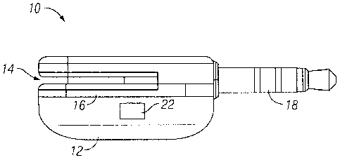
Otherwise,
identify the bit found as a 0.
[0128] Once the peak is determined, update the bit length based on the peak
found: if the
peak found was a 0, update with the value of Step 5; otherwise, use the value
of step 6.
Predictive Digitizing
[0129] Predictive digitizing of detected peaks in the incoming signals does
not treat the list
of peaks as facts. It first finds bit length, and then seeks to a point in the
peak list where the
next relevant peak should be. Once it reaches this location, it then searches
before and
after the location for the nearest peak. The process then checks the polarity
of this peak
compared to the previous peak examined. If the polarities are the same, the
bit found is
identified as a 1. Otherwise, it is identified as a 0. This method of
digitizing a peak list is
effective in that it simply ignores any information that is likely irrelevant.
[0130] The flowchart 1400 ends at block 1412 where decoding engine 110
converts the
array of digitized bits into words of card information. This converting
process locates the bit
sequence that is the start sentinel in the array. At that point, it takes
frames of bits (e.g., 5
bits for track 2, 7 bits for track 1) and decodes them based on a symbol
table. Along the
way, the process constantly checks for parity and the LRC at the end to ensure
the data is
correct. If there are any errors in parity, LRC, or track length, blocks 1406-
1412 may be
repeated with a different set of parameters to get the correct signal data.
[0131] When a card swipe begins, decoding engine 110 can combine various peak
detectors and digitizers discussed above in order to cover various ranges of
degradation in
quality of the analog input signal generated by card reader 10. In some
embodiments,
different process combinations and parameters can be chosen and optimized
depending on
the hardware platform of the mobile device. These combinations and parameter
values can
be pre-determined based on experimentation and testing and initialized upon
starting of the
decoding process. The decoding then runs through all processes specified and
runs
certain specific processes multiple times in order to get the correct signal.
Such decoding
18
CA 02812251 2013-03-21
WO 2012/051067 PCT/US2011/055375
process allows automatic scaling and adjustment during each run to account for
different
amounts of noise, sampling speed variations, signal ringing, and swipe
direction.
Card present transaction without information sharing
[0132] In the example of FIG. 1, user interaction engine 120 is a software
application
running on mobile device 100 associated with a payee (merchant) that enables
the payer
(buyer) and the merchant to interact with transaction engine 130 to complete a
financial
transaction. More specifically, it may take input of information related to
the financial
transaction from the buyer and/or the merchant, provide such input to
transaction engine to
initiate and complete the transaction, and present the result of the
transaction to the buyer
and the merchant. Here, the input of information accepted by user interaction
engine 120
may include but is not limited to one or more of: amount of the transaction,
including list
price and optionally tips, additional notes related to the transaction such as
written
description and/or pictures of the item to be purchased, authorization and/or
signature of the
buyer.
[0133] In some embodiments, other than the conventional keyboard, user
interaction
engine 120 may utilize a touch screen of mobile device 100 to enable the buyer
and the
merchant to input numbers, characters, and signatures by touching the screen
via a stylus
or a finger.
[0134] In some embodiments, in addition to the result of the transaction, user
interaction
engine 120 may also present products or services provided by the merchant to
the buyer in
combination of one or more of text, pictures, audio, and videos, and enable
the buyer to
browse through the products and services on the mobile device to choose the
one he/she
intended to purchase. Such product information can be stored and managed in
product
database 150.
[0135] In the example of FIG. 1, transaction engine 130 takes as its input the
decoded
credit card information from decoding engine 110 and transaction amount from
user
interaction engine 120. Transaction engine 130 then contacts third party
financial
institutions such as an acquiring bank that handles such authorization
request, which may
then communicate with the card issuing bank to either authorize or deny the
transaction. If
the third party authorizes the transaction, then transaction engine 130 will
transfer the
amount of money deducted from the account of the card holder (e.g., the buyer)
to an
account of the merchant and provide the transaction results to user
interaction engine 120
for presentation to the buyer and the merchant. In this manner, the merchant
may accept a
payment from the buyer via card reader 10 and mobile device 100.
19
CA 02812251 2013-03-21
WO 2012/051067 PCT/US2011/055375
[0136] In the example of FIG. 1, although mobile device 100 is associated with
the
merchant, transaction engine 130 running on mobile device 100 protects the
privacy of the
buyer/payer during the card-present transaction by taking card information
from the buyer
directly from decoding engine 110 and do not share such information with the
merchant via
user interaction engine 120. Here, the card information that are not shared
with the
merchant includes but is not limited to, card number, card holder's name,
expiration date,
security code, etc. In essence, transaction engine 130 serves as an
intermediary between
the buyer and the merchant, so that the buyer does not have to share his/her
card
information with the merchant as in a typical card-present transaction or an
online
transaction. Still, the buyer is able obtain an itemized receipt for the
transaction completed
as discussed later.
[0137] In some embodiments, although transaction engine 130 does not share
card
information of the buyer to the merchant, it may present identity information
of the buyer,
such as a picture of the buyer on record in user database 140, with the
merchant via user
interaction engine 120 so that merchant can reliably confirm the identity of
the buyer during
the card-present transaction to prevent credit fraud.
[0138] In the example of FIG. 1, user database 140, product database 150, and
transaction
database 160 can be used to store information of buyer and the merchant,
products and
services provided by the merchant, and transactions performed, respectively.
Here, user
information (e.g., name, telephone number, e-mail, etc.) can be obtained
through online
user registration and product information can be provided by the merchant,
while
transaction database 160 is updated every time a transaction is processed by
the
transaction engine 130. Information stored can be selectively accessed and
provided to the
buyer and/or merchant as necessary.
[0139] In the example of FIG. 1, transaction engine 130 communicates and
interacts with
the third party financial institution, user database 140, product database
150, and
transaction database 160 over a network (not shown). Here, the network can be
a
communication network based on certain communication protocols, such as TCP/IP
protocol. Such network can be but is not limited to, internet, intranet, wide
area network
(WAN), local area network (LAN), wireless network, Bluetooth, WiFi, and mobile
communication network. The physical connections of the network and the
communication
protocols are well known to those of skill in the art.
Dynamic receipt
[0140] In various embodiments, upon the completion of a financial transaction
through, for a
non-limiting example, card reader 10 connected to mobile device 100 associated
with a
CA 02812251 2013-03-21
WO 2012/051067 PCT/US2011/055375
merchant, transaction engine 130 running on the mobile device 100 can be
configured to
capture additional data associated with the transaction and incorporate the
additional data
into a dynamic receipt for the transaction, wherein in addition to transaction
information
typically included in a conventional receipt, the dynamic receipt may also
include additional
environmental information of the transaction. For non-limiting examples, the
financial
transaction can be an electronic transaction conducted over the Internet or a
card present
point-of-sale transaction where the buyer/payer makes the purchase at a store
front, other
"brick-and-mortar" location, or simply in presence of a merchant/payee.
[0141] In some embodiments, the additional environmental information included
in the
dynamic receipt may include information pertaining to the transaction
environment. In one
non-limiting example, a mobile device equipped with a Global Positioning
System (GPS)
receiver can be used to capture the coordinates/location of the transaction,
and record it as
a part of the information on the dynamic receipt. This way, the physical
location of the point
of sale (which may be different from the merchant/payee's registered address)
can be
recorded and used by transaction engine 120 to verify the transaction. In
another non-
limiting example, a mobile device equipped with a camera and/or audio and/or
video
recorder can be used to capture a photo and/or a video and/or an audio
recording of the
product or service involved in the transaction and incorporate such data or
link/reference to
such data into the dynamic receipt. In another non-limiting example, a mobile
device with a
biometric scanner can be used to scan the fingerprint or palm print of the
buyer/payer
and/or merchant/payee and includes at least a portion of such information in
the dynamic
receipt. In another non-limiting example, the mobile device can record certain
information
associated with the transaction in the dynamic receipt, wherein such
information includes
but is not limited to, how quickly the buyer swipes the card, the angle at
which the card is
swiped. In another non-limiting example, special characteristics of the card
being swiped,
also referred to as the magnetic fingerprint of the card, can be recorded and
included in the
dynamic receipt.
[0142] In some embodiments, the dynamic receipt can be in electronic form that
can be
accessed electronically or online and may also include link or reference
pointing to
multimedia information such as image, video or audio that are relevant to the
transaction.
[0143] In some embodiments, transaction engine 130 can use the environmental
information included in the dynamic receipt to assess risk associated with a
transaction. For
a non-limiting example, if the GPS information indicates that the transaction
is taking place
in a high crime/high risk area, the risk associated with the transaction is
adjusted
accordingly, and the buyer's bank may be notified accordingly. Alternatively,
biometric
21
CA 02812251 2013-03-21
WO 2012/051067 PCT/US2011/055375
information scanned and included in the dynamic receipt can be used for
identity verification
purposes to prevent identity theft and credit fraud.
[0144] In some embodiments, transaction engine 130 can use the dynamic receipt
can be
used as a non-intrusive way to communicate with the buyer and/or the merchant.
For a
non-limiting example, the additional information included in the dynamic
receipt can be used
to make offers to the buyer. If a dynamic receipt includes the GPS location of
the point of
sale of the transaction, coupons or other promotional offers made by vendors
at nearby
locations can be presented to the buyer when the buyer chooses to view the
receipt
electronically online. Alternatively, if a specific product involved the
transaction can be
identified by the transaction engine either directly through product
description or indirectly
by analyzing pictures or videos taken, offers of similar or complementary
products can be
made by a vendor to the merchant of the product.
[0145] In some embodiments, transaction engine 130 may notify buyer and/or the
merchant
of the receipt via an electronic message, which can be but is not limited to,
an email
message, a Short Message Service (SMS) message, Twitter, or other forms of
electronic
communication. The recipient of the electronic message may then retrieve a
complete
itemized dynamic receipt online at his/her convenience via a telephone number
on his/her
record in user database 140 to retrieve his/her electronic receipts stored in
transaction
database 160. In some embodiments, the electronic message may include an
indication
such as a code that the recipient can use to retrieve the electronic receipt
online as an
alternative or in combination with the telephone number.
[0146] FIG. 15 depicts a flowchart of an example of a process to support
financial
transaction between a payer and a payee through a miniaturized card reader
connected to a
mobile device. In the example of FIG. 15, the flowchart 1500 starts at block
1502 where an
amount of a financial transaction is provided through an interactive user
application
launched on the mobile device as shown in FIG. 16(a). The flowchart 1500
continues to
block 1504 where a miniaturized card reader structured to minimize swipe error
is
connected to the mobile device as shown in FIG. 16(b). The flowchart 1500
continues to
block 1506 where a card is swiped through the card reader to initiate the
financial
transaction as shown in FIG. 16(c). The flowchart 1500 continues to block 1508
where the
payer confirms the amount of the card-present transaction via a signature
signed via the
interactive user application on the mobile device to complete the transaction
as shown in
FIG. 16(d). Note that the signature is required as an additional layer of
confirmation for the
protection for the payer even when such signature may not be technically
required to
authorize the transaction. The flowchart 1500 continues to block 1510 where
result of the
transaction is received and presented to the payer and/or merchant as shown in
FIG. 16(e).
22
CA 02812251 2013-03-21
WO 2012/051067 PCT/US2011/055375
The flowchart 1500 ends at block 1512 where an electronic receipt of the
transaction is
provided to the payer in the form of an electronic message as shown in FIG.
16(f).
[0147] In one embodiment, a longitudinal plane of the of the output jack 18
lies within the
plane that the card travels in the slot 14 within 5 mm, and in another
embodiment within
3mm.
[0148] Referring now to FIG. 17, in one embodiment of the present invention an
integrated
read head system includes mobile device 212 with an audio jack 214 at least
one
microphone input port 216. A read head 218 is physically coupled to the mobile
device 212.
The read head 218 has a slot 220 for swiping a magnetic stripe of a financial
transaction
card to enable a financial transaction between a buyer and seller. The read
head 218 reads
data on the magnetic stripe and produces a signal indicative of data stored on
the magnetic
stripe. The read head 218 has an output jack 222 that physically connects the
read head
218 to at least one of the audio jack 214 or microphone pod 216 of the mobile
device 212.
The read head 218 provides the signal to the mobile device 212. The signal is
decoded at
the mobile device 212. The decoding includes determining pulses in the signal
and
converts at least some of the pulses to characters.
[0149] In another embodiment of the present invention, a method is provided
for conducting
a financial transaction with a financial transaction card using the integrated
read head
system 210.
[0150] The foregoing description of various embodiments of the claimed subject
matter has
been provided for the purposes of illustration and description. It is not
intended to be
exhaustive or to limit the claimed subject matter to the precise forms
disclosed. Many
modifications and variations will be apparent to the practitioner skilled in
the art.
Particularly, while the concept "component" is used in the embodiments of the
systems and
methods described above, it will be evident that such concept can be
interchangeably used
with equivalent concepts such as, class, method, type, interface, module,
object model, and
other suitable concepts. Embodiments were chosen and described in order to
best describe
the principles of the invention and its practical application, thereby
enabling others skilled in
the relevant art to understand the claimed subject matter, the various
embodiments and with
various modifications that are suited to the particular use contemplated.
23