Note : Les descriptions sont présentées dans la langue officielle dans laquelle elles ont été soumises.
CA 02813308 2013-03-28
WO 2012/044690 PCT/US2011/053694
COAXIAL CABLE CONNECTOR INSTALLATION TOOL
CROSS REFERENCE TO RELATED APPLICATION
[0001] This application claims priority to U.S. Patent Application No.
12/895,562, filed September 30, 2010, the entirety of which is incorporated by
reference
herein.
FIELD OF THE INVENTION
[0002] The present invention is generally directed toward a cable
crimping and
stripping device which has the capacity to eject scrap material from between
the stripping
blades.
BACKGROUND OF THE INVENTION
[0003] Coaxial cables are frequently used in the transmission of audio
and video
signals, such as in the cable television industry, and as interconnects
between electronic
components. Coaxial cable consists of a center core wire surrounded by a
dielectric
insulator which is further wrapped in flexible metal shielding. A final layer
of plastic jacket
surrounds the metal shielding.
[0004] Termination of the coaxial cable is often performed by applying
a
compression fitting, such as a THOMAS & BETTS brand SNAP 'N SEAL connector. To
attach such a connector, the plastic jacket must be removed to expose metal
shielding, and a
portion of the metal shielding and dielectric insulator closer to the end of
the coaxial cable
1
CA 02813308 2013-03-28
WO 2012/044690 PCT/US2011/053694
must further be removed to leave a section of exposed center core wire. A
compression
fitting is then installed on the end using a crimping tool. One such tool for
stripping the
wire and applying the compression fitting is the THOMAS & BETTS brand IT1000
connector installation tool. This tool has dual blades that allow simultaneous
removal of the
plastic jacket near the end of the wire, as well as the plastic jacket, metal
shielding, and
dielectric insulator further from the end of the wire.
[0005] However, in prior art cable stripping tools, the area between
the blades
frequently got clogged with a portion of the plastic jacket removed from the
cable. Since
the operator of the tool most likely uses one hand to hold the coaxial cable
and the other to
hold the tool, removal of that discarded plastic jacket portion was
particularly difficult
without releasing the coaxial cable and using a small tool to dislodge it. In
difficult cable
installation areas, such as on utility pole-mounted cables, removal of the
scrap material in
order to use the stripping tool was particularly difficult.
SUMMARY OF THE INVENTION
[0006] An improved cable stripping and crimping tool is disclosed that
overcomes the problem of discarded scrap material becoming lodged between
stripping
blades. The disclosed tool includes an ejector pin that easily allows removal
of the
discarded material from between the blades by pressing a button.
BRIEF DESCRIPTION OF THE DRAWINGS
[0007] Further advantages of the invention will become apparent by
reference to
the detailed description of preferred embodiments when considered in
conjunction with the
drawings:
[0008] FIG. 1 depicts a perspective view of the coaxial cable tool as
viewed
from the rear and left of the device.
CA 02813308 2013-03-28
WO 2012/044690 PCT/US2011/053694
[0009] FIG. 2 depicts a second perspective view of the coaxial cable
tool as
viewed from the rear and right of the device.
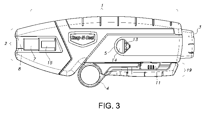
[0010] FIG. 3 depicts a left side view of the coaxial cable tool.
[0011] FIG. 4 depicts a right side view of the coaxial cable tool.
[0012] FIG. 5 is an exploded view of the coaxial cable tool.
[0013] FIG. 6 depicts the coaxial cable tool showing the internal
components as
viewed from the left side of the device.
[0014] FIG. 7 depicts the coaxial cable tool showing the internal
components as
viewed from the right side of the device.
DETAILED DESCRIPTION
[0015] The following detailed description is presented to enable any
person
skilled in the art to make and use the invention. For purposes of explanation,
specific
details are set forth to provide a thorough understanding of the present
invention. However,
it will be apparent to one skilled in the art that these specific details are
not required to
practice the invention. Descriptions of specific applications are provided
only as
representative examples. Various modifications to the preferred embodiments
will be
readily apparent to one skilled in the art, and the general principles defined
herein may be
applied to other embodiments and applications without departing from the scope
of the
invention. The present invention is not intended to be limited to the
embodiments shown,
but is to be accorded the widest possible scope consistent with the principles
and features
disclosed herein.
[0016] Referring to the drawings, FIG. 1. illustrates an exemplary
embodiment
of the coaxial cable stripper having an elongated body 1 with one end having a
nose 2, and
3
CA 02813308 2013-03-28
WO 2012/044690 PCT/US2011/053694
the other end having a scrap ejector button 3. The primary purpose of the nose
end of the
tool is for crimping connectors to the coaxial cable. The nose 2 is configured
to accept a
cable connector into a recessed area accessible from one side of the body
called the
connector seating 7. The cable connector is prevented from sliding out of the
nose end of
the body 1 by a raised lip referred to herein as the connector retainer 8.
[0017] The cable is stripped at the blade carrier end of the tool. As
will be
appreciated by FIG. 6, blade carrier 17 is slidably mounted relative to casing
22 of the tool.
Blade carrier spring 16 pushes blade carrier 17 toward scrap ejector button 3.
Opening 5 is
configured to receive the end of a coaxial cable that will be terminated with
a connector. In
the tool's normal state, the opening 5 is blocked from receiving a coaxial
cable by cable
stripping blades 13 and 14, which are mounted directly on blade carrier 17. As
can be seen
from FIG. 5, cable stripping straight blade 13 and cable stripping notched
blade 14 are
parallel to each other, but have slightly different shapes. Cable stripping
notched blade 14
has a mostly straight edge with a notch that can accommodate the center core
wire of the
cable. It is intended to cut all but the center core wire of the coaxial
cable. Cable stripping
straight blade 13 has a straight edge without a notch, and, when mounted on
blade carrier 3,
does not extend as far away from the nose end of the body 1 as cable stripping
notched
blade 14. Cable stripping blade 13 is suitable for cutting into the jacket of
the cable without
cutting into the metal shielding of the cable.
[0018] Depressing scrap ejector button 3 toward nose 2 causes the
cable
stripping blades 13 and 14 to move toward nose 2, thus allowing the coaxial
cable to pass
through the opening 5. As can be seen from FIG. 2, the coaxial cable's passage
through the
body 1 is impeded by cable stop 6 located on the opposite side of body 1 as
the opening 5.
Cable stop 6 allows the end of the coaxial cable to be properly positioned
relative to cable
4
CA 02813308 2013-03-28
WO 2012/044690 PCT/US2011/053694
stripping blades 13 and 14 so that the proper amount of cable material will be
stripped
away.
[0019] To strip the coaxial cable, the scrap ejector button 3 is
depressed toward
nose 2 of the tool, causing the cable stripping blades 13 and 14 to move
toward nose 2 of
the tool. The cable is then inserted into opening 5 until it touches cable
stop 6. The scrap
ejector button 3 is then released, and blade carrier spring 16 causes cable
stripping blades 13
and 14 to exert force against the coaxial cable. The tool is then rotated
about the axis of
coaxial cable, causing the blades to cut into the cable. Rotation of the tool
about the cable is
facilitated by molded grip 4 which allows the operator to insert a finger or
thumb into it for
easy maneuvering of the tool. Cable stripping notched blade 14 will cut into
all layers of the
cable down to the center core wire. Cable stripping straight blade 13 will cut
only into the
plastic jacket.
[0020] When the blades have cut sufficiently far into the cable, the
cable is then
pulled away from the tool. Cable stripping notched blade 14 will shear all
layers of the
coaxial cable that surround the central core wire away from the end of the
cable. This
discarded material will fall away toward the cable stop 6 and can exit the
tool through an
opening in cable stop 6. Cable stripping straight blade 13 will shear away
only the plastic
jacket of the cable. However, this discarded portion of the jacket will remain
lodged in the
area between cable stripping straight blade 13 and cable stripping notched
blade 14.
[0021] The design of the tool allows the jacket scrap to be ejected
simply by
depressing the scrap ejector button 3. As can be seen from FIG. 5 and FIG. 6,
an ejector pin
18 is positioned within casing 22 of the tool such that the tip end, which is
closest to the
opening 5, rests between cable stripping straight blade 13 and cable stripping
notched blade
14. In a preferred embodiment, the ejector pin 18 is secured at the end near
nose 2 by
grooves in casing 22 of the tool. The ejector pin 18 serves to remove the
discarded jacket
CA 02813308 2013-03-28
WO 2012/044690 PCT/US2011/053694
material that gets caught between the cable stripping straight blade 13 and
the cable
stripping notched blade 14. The ejector pin 18 is of sufficient length that
the tip extends just
beyond the nose-end edge of opening 5. As the scrap ejector button 3 is
depressed, cable
stripping notched blade 14 and cable stripping straight blade 13 move toward
the nose 2 of
the tool just beyond the tip of ejector pin 18. Any jacket scrap that remains
between the two
blades is pushed out by the tip of the ejector pin 18 and can fall out of the
tool through
opening 5.
[0022] It should be appreciated that only one hand is required to
operate the tool.
This is particularly helpful in situations where the operator needs to hold on
to the cable to
prevent it from dropping, for example when on a ladder or when working at the
top of a
utility pole. The tool can be fully used with the coaxial cable in one hand
and the tool in the
other. Positioning the cable in the opening 5, depressing scrap ejector button
3, rotating the
tool about the coaxial cable, and ejecting the discarded jacket material can
all be performed
with one hand. Similarly, crimping the connector to the end of the cable can
be performed
with just one hand on the tool, and the other on the coaxial cable.
[0023] Once the cable end has been stripped, the tool can be used to
crimp a
connector onto the coaxial cable. Crimping is performed through the action of
crimping pin
15 pushing a compression connector against connector retainer 8, thus, sealing
it against the
cable. Crimping pin 15 is positioned within a groove of casing 22 such that it
can slide
toward the nose-end of the tool. As can be seen from FIG. 5 and FIG. 6, lever
9 is located
such that it pivots about pivot point 12. Lever 9 has a handle end, located
within molded
grip 4, and a nose-end that is configured to apply pressure against crimping
pin 15.
Crimping pin 15 is coupled to the nose-end arm of lever 9 such that the nose-
end arm of
lever 9 and crimping pin 15 move together toward the nose-end of the tool when
the handle
end of lever 9 is squeezed toward the body of the tool. Both the nose-end of
lever 9 and
6
CA 02813308 2013-03-28
WO 2012/044690 PCT/US2011/053694
crimping pin 15 are coupled to casing 22 through the use of crimping pin
spring 20. The
crimping pin spring 20 keeps the crimping pin 15 in a retracted state away
from the nose-
end of the tool, facilitating insertion of a connector into the connector
seating 7. Due to the
force of crimping pin spring 20 pulling nose-end of lever 9 to achieve lowest
spring tension,
the handle-end of the lever 9 is pushed away from the body of the tool as it
pivots about
pivot point 12. As a result, the handle assembly 19 sticks out from the body
of the tool in
the state of lowest spring tension of crimping pin spring 20.
[0024] For compact storage of the tool, the handle assembly 19 can be
secured
against the body of the tool through the use of handle latch 11. Handle latch
11 is slidably
coupled to molded grip 4 and is configured to engage a catch on casing 22 of
body 1. To
lock the tool, the handle assembly 19 is squeezed in toward the body 1, and
the handle latch
11 is slid toward the catch on the body 1. Alternatively, a wire bail on
handle assembly 19
that snags a portion of the body 1 may be employed to secure the handle
assembly 19
against the body 1 of the tool.
[0025] An additional feature of the design of the tool is that the
cable stripping
blades 13 and 14 may easily be replaced as required. To replace the blades,
screws which
hold cover 10 of the tool to casing 22 are removed. Cover 10 is then lifted
off, and the
blade carrier 3 is removed from the channel in the casing 22 in which it sits,
along with
blades that are attached to it. After the cable stripping blades 13 and 14 are
replaced, the
blade carrier 17 can be reinserted into its grooves in the casing 22, and the
cover 10 screwed
back on.
[0026] The casing 22, cover 10, and blade carrier 17 are preferably
made of
molded plastic which makes the tool light and inexpensive. However, the tool
can also be
made of cast metal or any other rigid material. It should be appreciated that
in a preferred
7
CA 02813308 2013-03-28
WO 2012/044690 PCT/US2011/053694
embodiment, the body 1 can be ergonomically shaped and include a textured
surface to
reduce the likelihood of the tool slipping out of the hand.
[0027] The terms "comprising," "including," and "having," as used in
the claims
and specification herein, shall be considered as indicating an open group that
may include
other elements not specified. The terms "a," "an," and the singular forms of
words shall be
taken to include the plural fonn of the same words, such that the terms mean
that one or
more of something is provided. The term "one" or "single" may be used to
indicate that one
and only one of something is intended. Similarly, other specific integer
values, such as
"two," may be used when a specific number of things is intended. The terms
"preferably,"
"preferred," "prefer," "optionally," "may," and similar terms are used to
indicate that an
item, condition or step being referred to is an optional (not required)
feature of the
invention.
[0028] While the invention has been described with respect to a
limited number
of embodiments, those skilled in the art, having benefit of this disclosure,
will appreciate
that other embodiments can be devised which do not depart from the scope of
the invention
as disclosed herein. Accordingly, the scope of the invention should be limited
only by the
attached claims.
[0029] All references throughout this application, for example patent
documents
including issued or granted patents or equivalents, patent application
publications, and non-
patent literature documents or other source material, are hereby incorporated
by reference
herein in their entireties, as though individually incorporated by reference,
to the extent each
reference is at least partially not inconsistent with the disclosure in the
present application
(for example, a reference that is partially inconsistent is incorporated by
reference except
for the partially inconsistent portion of the
reference).
8