Note : Les descriptions sont présentées dans la langue officielle dans laquelle elles ont été soumises.
CA 2819375 2017-04-10
1
LOCK
The invention relates to a lock, in particular to a panic lock for a door of a
refrigeration room or
freezer room.
Locks of this type on the one hand serve for being able to lock the door from
the outside, so that
no unauthorised person can enter from the outside, but also on the other hand
to ensure that the
door can always be opened from the inside. Such doors are applied for escape
ways,
emergency exits and likewise and in particular they are stipulated with regard
to refrigeration
rooms and freezer rooms, in order to ensure that a person accidentally shut
inside can leave the
room at any time.
Mortise locks which have this function are counted as belonging to the state
of the art. They
comprise a door handle on their inward and outward sides and these via a
common square
shank engage in a hub which is rotatably mounted within the lock. The hub
comprises a catch,
with which the latch bolt can be displaced into the opening position. A
locking cylinder is
integrated for the dead bolt function and this activates a dead bolt which is
arranged parallel to
the latch bolt, usually therebelow and which can be extended and retracted by
way of turning the
key in the cylinder lock. On the inward side, an operating element is fixedly
connected to the
cylinder lock, instead of the key, so that the door can be unlocked from the
inside also without a
key.
The disadvantage of this known lock, in particular if it is applied for the
door of a refrigeration
room or freezer room, is that two operating elements must always be actuated
one after the
other, in order to open the lock and thus the door. Firstly, the dead bolt is
to be unbolted by way
of the operating element arranged on the cylinder lock, whereupon the door
handle located
thereabove is to be actuated.
Against this background, it is the object of the invention to design a panic
lock such that it can be
operated from the inside, in a simpler, in particular intuitive manner.
According to the invention, this object is achieved by the exemplary
embodiments of the
invention disclosed subsequently herein.
The lock according to the invention, which in particular is envisaged and
provided as a panic lock
for a door of a refrigeration room or freezer room, comprises a chassis, in
which a latch bolt
CA 02814375 2013-04-11
2
which is bevelled on at least one side and is impinged by spring force in the
extension direction,
is displaceably guided. A hub is rotatably mounted within the lock and is
designed in a divided
manner and comprises an inward hub part which is actuatable via an inward
operating lever.
This inward hub part comprises a catch, with which the latch bolt is
actuatable at least in the
retraction direction. The other part of the hub is formed by the outward hub
part actuatable via an
outward operating lever and comprising an outward catch, with which the latch
bolt can be
actuated in the retraction and extension direction. Moreover, according to the
invention, means
are provided within the lock, which, given a non-actuation of the operating
lever, bring the
catches of the hub parts into a neutral position, in which the catches are
disengaged from the
latch bolt. Moreover, means are provided for locking the outward catch in its
neutral position, and
these can be operated from the outward side.
Outward and inward in the context of the invention are to be understood as
direction
specifications according to DIN 107. With a refrigeration room door which
always opens to the
outside, the outward part of the lock lies close to the outer side of the
door, thus on the warm
side, whereas the inward part lies close to the inner side directed to the
room to be closed, thus
on the cold side.
The basic concept of the lock according to the invention is to design the
panic function of the lock
as simple as possible, i.e. to permit an intuitive operation, as is
particularly advantageous in
panic situations, since it can be accomplished quasi without the person having
to think. The lock
according to the invention, even if it is locked from the outside, i.e. is
bolted with regard to its
operation, can also be opened from the inside at any time, and specifically by
way of a simple
actuation of the operating lever in the opening position. Here, depending on
the design of the
operating lever, a commercially available door handle can be applied and this
can be opened
from the inside by way of simple pushing, as when opening a room door,
independently of
whether the lock has been bolted from the outer side or not. Not only is an
increased security
against erroneous operation ensured by way of this, but moreover there is the
advantage also in
practical operation that it is always only one operating lever which is to be
actuated on the inner
side.
The lock according to the invention is particularly advantageous for the door
of a refrigeration
room or freezer room, but however its application is not necessarily limited
to this and it may also
be used as a panic lock for other applications or also for other purposes.
With regard to the construction of the lock, it is particularly favourable if
the latch bolt which is
present in any case also forms the dead bolt, with which the lock can be
brought into its bolting
CA 2819375 2017-04-10
3
=
position in the strike plate. Thereby, the design of the lock mechanism is
advantageously such
that for the latch bolt, a first extension position is envisaged, in which
only the latching function is
effective, and that moreover a second extension position reaching beyond the
first extension
position is provided, which fulfils the bolting function. The first extension
position thus
encompasses the usual latching function, in which the latch bolt moves into
the lock against
spring force, typically when the door is closed, and the latch bolt with its
oblique surface is
pushed back by the strike plate. In the second extension position on the other
hand, the latch
bolt is pushed further into the strike plate, so that a bolting between the
lock and the strike plate
is effected, which is significantly more difficult to manipulate that the
first extension position.
In particular, for the use of a lock for a door of a refrigeration room or
freezer room, it is
advantageous to design the latch bolt bevelled on both sides. Thereby, apart
from the usual
bevelling which on closing the door comes into contact with the outward side
of the strike plate,
in order to press the latch bolt into the lock against spring force, a
bevelling is also provided on
the other side and this is typically shorter and serves for mechanically
pulling the door a little
more onto the frame by way of the extension (which is to say the moving-out)
of the latch bolt
from the first extension position into the second extension position, by which
means a particularly
tight bearing contact is effected, which ensures that the door seals bear
firmly and seal in a good
manner over their complete length.
Advantageously, according to a further formation of the invention, not only is
the outward, but
also the inward catch is impingable in the extension direction, so that the
latch bolt can also be
brought from the inside into the second extension position. This is
particularly advantageous if a
person enters into the refrigeration room or freezer room and works there for
a longer time and
wishes to ensure a sealed closure during this time.
In order to provide a bolting of the lock from the outside in a simple design
manner, according to
a further development of the invention, a receiver for a locking cylinder is
provided in the chassis
of the lock and is designed such that the locking cylinder is only accessible
from the outside, i.e.
that it is only accessible from the outward side of the lock with a key. The
lock in this region in
contrast is designed in a closed-walled manner from the inward side. Such
locking cylinders are
inexpensively available and; as the case may be, can be combined with closure
systems which
are also applied in other locks. Thereby, the catch of the closure cylinder is
arranged such that
on rotation of the key, it actuates a mechanism within the lock and this
mechanism locks or
releases the outward hub part, and specifically in the neutral position of the
outward catch, so
that the actuation of the inward hub part and thus also of the catch is
independent of this. Thus
with the locking cylinder it is not a dead bolt which is extended out of the
lock, as is normally the
CA 02814375 2013-04-11
4
case, but in contrast it serves to fixing the outward hub part via a suitable
locking mechanism, so
that an actuation from the outside and thus an opening of the lock from the
outside is no longer
possible.
In order to guide the catches of the hub parts into their neutral position,
according to a further
development of the invention, each hub part is provided with a cam surface
directed roughly
tangentially to the rotation axis of the hub, on which surface a slide
impinged by spring force
bears, and this slide is displaceably guided within the chassis and is
impinged by spring force
obliquely to this cam surface, preferably at an angle of about 45 thereto.
This slide which in the
neutral position has a counter-surface bearing on the cam surface is designed
and arranged
such that it automatically sets the hub part with its catch back into the
neutral position as is
described in detail further below.
Usefully, a detent which fixes the catch of the respective hub part in its
neutral position is
provided within the lock. The catch is advantageously moved into this detent
position by the
slide, and the springs of the slide and detent are therefore to be designed
such that the slide can
automatically bring the catch of the associated hub part into the detent
position.
The construction of the lock can be effected in a manner which is stable and
particularly simple
with regard to design, if according to a further development of the invention,
the chassis
comprises a carrier plate which carries the components of the lock and which
is connected at a
longitudinal side to a forend, as is common with mortise locks.
The lock is advantageously designed as a mortise lock so that it can also
replace present locks
as the case may be, if these are to be replaced by such a panic lock equipped
with only one
actuation lever. Thereby, the operating levers are advantageously formed by
standard-compliant
door handles, so that the lock can receive standard-compliant handle
furnishings and can be
applied in standard-compliant doors without special designs.
The invention is hereinafter explained in more detail by way of one embodiment
shown in the
drawing. There are shown in:
Fig. 1 in a greatly simplified representation, a lock according to the
invention in the non-
actuated condition, and specifically
Fig. 1a in a view from inwards,
CA 02814375 2013-04-11
Fig. lb in a perspective inward view and obliquely to the rear and
Fig. lc in an outward view, with a removed carrier plate,
Fig. 2 the lock according to Fig. 1 in an opened position, in the
representation according
to Fig. 1,
Fig. 3 the lock according to Fig. 1 in a locking position, in
representations according to
Fig. 1,
Fig. 4 the lock according to Fig. 1, in an emergency-opened position, in
the
representations according to Fig. 1 and
Fig. 5 in an enlarged outward view, the lock in the locking position, with
a locking
cylinder.
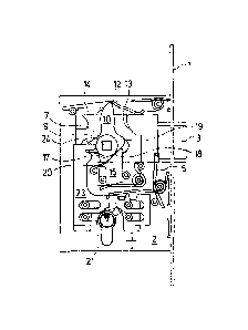
With the lock represented by way of the figures, it is the case of a mortise
lock with a forend 1
which can be inserted into a standardised recess of a rebated or non-rebated
door and fastened
in this by way of the forend 1. The forend 1 and a carrier plate 2 which is
arranged transversely
thereto and is fixedly connected thereto, form the chassis of the lock which
is surrounded by a
closed (not represented in the Figures) rectangular housing, as is common with
mortise locks.
The lock comprises a latch bolt 3 which is bevelled on two sides, and
comprises a first
longitudinal oblique surface 4 which is arranged on the side facing inwards
and is envisaged and
provided for the common latch or catch function, when the door with the lock
located therein is
shut and the oblique surface 4 hits the outward side of the strike plate, by
which means the latch
bolt 3 is retracted against the spring force of the spring 5 through the
forend 1 into the lock. After
moving over the edge of the strike plate, the latch bolt 3 automatically
extends or moves out
again by the force of the spring 5 and holds the door in the closed position.
This position (first
extension position) is represented in Fig. 1.
On the other side, the latch bolt 3 comprises a short oblique surface 6 which
is shorter than the
oblique surface 4 and is arranged on the outward side of the latch bolt 3.
This oblique surface 6
serves for pressing the latch bolt 3 further into the strike plate when it has
already snapped into
the strike plate, wherein the latch bolt 3 by way of the oblique surface 6
together with the lock
and the door, in which the lock is seated, is pulled into the door frame, by
which means it is
ensured that the door seal is impinged by force and this can be brought into
bearing contact on
CA 2819375 2017-04-10
6
all sides. With refrigeration room doors, the sealedness of the door is
ensured by way of this and
thus the cold flow via the door gap is prevented.
The oblique surfaces 4 and 6 extend almost up to the free outward end of the
latch bolt 3. The
oblique surface 4 thereby extends over almost the complete part of the latch
bolt 3 which
projects out of the forend 1 in the normal position, whereas the oblique
surface 6 only extends
over about half of this part and then merges into a part running in a straight
line.
A hub which consists of two parts 7 and 8 and which is rotatably mounted
within the carrier plate
2 or the lock housing is provided for the actuation of the lock. The outward
hub part 7 comprises
a central squared recess 9 which is provided for receiving an operating lever
in the form of a
door handle. The inward hub part 8 likewise comprises a central squared recess
9 which is
envisaged for the positive-fit receiving of an inward operating lever in the
form of a door handle
arranged on the inner side of the door. The hub parts 7 and 8 can be moved
independently of
one another since they are separate from one another. Each hub part 7, 8
comprises a long
catch 10 and 11 respectively, with which the latch bolt 3 can be locked and
opened. With the
position of the catches 10 and 11 shown by way of Fig. 1, it is the case of a
neutral position, in
which the respective catch 10, 11 is fixed by detent and is not actively
connected to the latch bolt
3. The detent position is formed by a detent receiver 12 loaded by a spring
force. Thereby, a
common spring is provided for both catches 10 and 11.
In this neutral position, which is represented in Fig. 1, the catches 10 and
11 are disengaged.
The latch bolt likewise lies in the detent receiver 12 in a latching manner,
so that it cannot be
displaced further against the spring force of the spring 5.
The latch bolt 3 is formed within the lock housing by way of a sheet-metal
part, in which recesses
for mounting the hub parts 7 and 8 are formed and which comprises a surfaced
recessing on the
inward as well as on the outward side, for forming two cam tracks 13 and 14.
Such cam tracks
13 and 14 are provided on the inward as well as on the outward side of the
latch bolt 3 and lie
such that they can come into active connection with the catches 10 and 11 at
the respective
side. Thereby, the long cam track 13 serves for moving the latch bolt out of
the normal position
(first extension position) into the bolting position (second extension
position). The short cam track
14 or the projection which is.formed by way of this in the latch bolt 3,
serves for opening the lock,
and specifically independently of whether this is located in the first or in
the second extension
position.
CA 2819375 2017-04-10
7
In the normal position, the lock is located in the representation according to
Fig. 1, and the latch
bolt 3 is located in the first extension position, in which it is held by the
force of the spring 5 and
the detent receiver 12. In this position, the latch bolt 3 with regard to the
cam tracks 13 and 14 is
arranged at a distance to the respective catches 10 and 11, so that the latch
bolt 3 can be
pressed into the lock housing against spring force, in order to execute its
latching function
without contacting the catches 10, 11.
In Figure 3, the lock is represented in a position, in which it is brought
into the bolted position,
thus into the second extension position. This, as is shown in the
representation according to Fig.
3c, is effected by way of actuating the outward door handle opposite to the
opening direction,
thus by way of pulling up the otherwise horizontal door handle. By way of
this, the outward hub
part 7 with the catch 10 located thereon is pivoted in Fig. 3c in the
clockwise direction, by which
means the catch 10 abuts on the upper end of the cam track 13 and with a
further rotation
moves the latch bolt 3 out of its first extension position (Fig. 1) into the
bolting position (second
extension position), in which the oblique surface 6 pulls the latch bolt 3
with the lock and the door
towards the door frame, and the latch bolt 3 moves out or extends to such an
extent that it can
be no longer manipulated from the outside. As Fig. 3a illustrates, the inward
door handle with the
hub part 8 remains in its neutral position independently of this movement. For
the sake of
completeness, it is to be noted here that this second extension position can
also be effected by
way of actuating the inward door handle, by way of pulling up the door handle,
wherein the
outward door handle then remains in its neutral position.
The latch bolt 3 can be opened from this second extension position as well as
from the first
extension position by way of actuating the inward door handle with the inward
hub part 8 as well
as by actuating the outward door handle with the outward hub part 7. Fig. 2
represents how the
opening of the lock is effected, with which the outward door handle is
actuated to open by way of
the door handle being pushed downwards. Thereby, the latch bolt 3 is not only
moved out of the
second extension position, but also out of the first extension position, into
the opened position, in
which the latch bolt 3 lies completely within the lock and thus no longer
passes through the
forend 1 in a projecting manner. The movement of the latch bolt 3 in this case
is effected by the
outward catch 10 which comes to bear on the short cam track 14 and catches the
latch bolt 3 in
the retraction (moving-in) direction. As Figure 2a illustrates, the catch 11
thereby remains on the
other (inward) side in its neutral position in an unchanged manner. It is to
be understood that this
opening movement can be 'effected in the same manner by way of actuating the
inward door
handle, thus by pushing down the door handle which is located on the inner
side of the door.
CA 02814375 2013-04-11
8
Two slides 16 are provided on both sides, in order to bring the outward hub
part 7 and the inward
hub part 8 into their neutral position, and these in the installed condition
are essentially vertically
displaceable and impinged by spring force by a spring 15 in the upward
direction. In the installed
condition they have an oblique surface 17 which is inclined by about 45 to
the vertical and
which is actively connected to an oblique surface 18, and this latter
mentioned oblique surface is
integrally formed in the hub parts 7 and 8 in each case and is directed
essentially tangentially to
the hub parts 7 and 8. These oblique surfaces 18 which extend in each case
between two short
catches 19 and 20, in combination with the oblique surface 18 on the
respective slide 16, ensure
that irrespective of the position of the hub parts 7 and 8, these are
automatically brought into
their neutral position, in which the catches 10 and 11 are disengaged from the
latch bolt 3. In this
position, the oblique surface 17 of the slide 16 bears on the oblique surface
18 of the associated
hub in a surfaced manner.
A locking cylinder 21 (Fig. 5) is integrated into the lock and is only
accessible from the outward
side, thus from the outer side of the door by way of a key, in order to secure
the lock from
entering form the outside. The inside of the lock is covered by the housing in
this region, at the
inward side. The locking cylinder 21 in a manner known per se comprises a
catch 22 which on
turning the key travels a path about the cylindrical part of the locking
cylinder. The locking
cylinder with the catch 22 is clearly visible in Fig. 5. The outward hub part
7 can be locked by
way of the locking cylinder 21. For this, a sheet-metal part 23 is
displaceable within the lock in
the transverse direction, thus in a direction parallel to the movement
direction of the latch bolt 3
and comprises a pawl 24, with which the outward hub part 7 can be locked, by
way of the pawl
24 moving the direction of the forend 1 and thus fixing the hub part 7. For
this, the catch 10 must
however be located in its neutral position, since otherwise the pawl 24 cannot
be introduced into
the hub part 7. Thus by way of the closable locking cylinder 21, it is not a
bolt which is moved
into the strike plate which is otherwise common with locks, but it is
exclusively the movement of
the outward door handle and thus the actuation of the latch bolt 3 from the
outside which is
blocked.
As is illustrated in Fig. 4, given a blocked hub part 7 (see Fig. 4c), the
latch bolt 3 also can be
completely retracted into the lock housing and thus the door opened, via the
inward hub part 8
and the door handle which is connected thereto, by way of simply pushing down
the door
handle. Thereby the movement of the door handle is effected onto the inward
hub part 8, from
there via the inward catch 11 onto the short cam track 14 and thus onto the
latch bolt 3. Thereby,
the locking of the outward hub part 7 remains unaffected.
CA 02814375 2013-04-11
9
List of reference numerals
1 forend
3 latch
4 long oblique surface of 3
spring
6 short oblique surface of 3
7 outward hub part
8 inward hub part
9 recess for door handle
outward long catch
11 inward long catch
12 detent receiver
13 cam path long
14 cam path short
slide spring
16 slide
17 oblique surface of 16
18 oblique surface on the hub part
19 short catch
short catch
21 locking cylinder
22 catch
23 sheet-metal part
24 pawl