Note : Les descriptions sont présentées dans la langue officielle dans laquelle elles ont été soumises.
CA 02814611 2013-04-12
WO 2012/049637
PCT/IB2011/054506
1
DESCRIPTION
"HEAT RECOVERY SYSTEM, ITS HEAT RECOVERY PROCESS AND USE"
Technical field of the invention
The present invention relates to a heat recovery system
functioning as heat exchanger that makes the recovery of a
part of the energy spent in the preparation of waste water,
including water from baths or kitchens, energy that is
usually lost when the water is drained into the sewer. This
energy can be recovered and reused to heat the bath water,
which is readily used, for example in the shower, or can be
stored in a storage tank.
This system is designed so that, together with any tub or
shower base, constitutes a heat recovery shower base or a
heat recovery bath tub. The energy recovery system is
basically constituted by a heat exchanger block that has a
tube preferably made of PVC and in its interior there is a
coil, preferably made of copper, and has technical
improvements that allow an increased efficiency in relation
to the known systems, as it will be explained further
ahead.
It is a first improvement the existence of a throttle plate
that holds the water in the drain hose, slowing the
draining.
It is a second improvement the filter to protect the system
against impurities, which prevents the clogging of the
system.
CA 02814611 2013-04-12
WO 2012/049637
PCT/EB2011/054506
2
It is a third improvement the modular construction and the
thermal insulation. The system has a compact structure that
benefits its rapid adaptation to any type of shower base or
bath tub on the market.
The dimensions and the materials of the various components
of the system can be adapted by a technician skilled in the
art in accordance with the requirements of the project
without leaving the scope of the invention.
Background of the invention
Are known from the prior art systems that use heat from
waste water including waste water from showers.
Thus, the document US4599870 by T. Hebert describes a
system in terms of heat usage, which has a traditional
block and a not/cold mixing valve. In its whole, it is a
fairly conventional and bulky system.
The document DE29806939U1 describes a system use of waste
water applied to shower facilities (including communal
showers) that also uses a block with a specific type of
building but once again not very compact, tailored to the
specific application, and a water heater for the hot water.
The document C12038928A1 describes a heat pump for the
production of hot water by a vapour compression system. It
has an evaporator that can capture the heat from the
CA 02814611 2013-04-12
WO 2012/049637
PCT/IB2011/054506
3
external environment while being subjected to the same
external environment. A coil system captures radiant heat
from the compressor. The operating principle is, therefore,
profoundly different from the present invention.
The Portuguese patent application PT104608 entitled "Heat
recovery system and corresponding trap" is the document of
the closest prior art. This patent application is an
alternative to this application in that the system presents
a different construction, thermodynamically more evolved
with energy efficiency improvements.
There are also operating advantages in particular by the
application of new parts with very specific functions and
which make the system much more adapted to the real
conditions of use. Better thermal insulation and an easier
assembly on site. Thus, the thermal balance is reached more
quickly, achieving energy savings of around 70%.
The system can also work in reverse, i.e. to cool tap water
that must be cooled before being used during a shower. In
very hot countries tap water is too hot. In these countries
there is a need to cool the water rather than to heat it.
Summary of the invention
It is an objective of the present invention to describe a
heat recovery system with heat exchanger for the heat
recovery that includes an inlet collector of a water
network installation of a shower, the water entering the
CA 02814611 2013-04-12
WO 2012/049637
PCT/1132011/054506
4
system at a temperature tl, an outlet for the water leaving
at the temperature t2, after passing through a coil that
is inside a plastic tube, inside which is the residual
water that flows from a drain of a bathing facility, water
that runs off and enters the pipe at a temperature t3, and
that after exchanging heat with the water that enters the
collector coil goes out into the sewer at a temperature t4,
the system comprising a traditional drain with a support
valve with cap, waste bucket, thread ring, top seal, bottom
seal to ensure the sealing with the floor of the baths,
where the heat exchanger system consists of a block
(compact casing) within which there is the heat exchanger
system, housing that is concealed under the floor of the
installation of the baths, the system having an additional
filter at the entrance of the tubular deposit that protects
the system from any possible clogging, and with means to
ensure a turbulent flow inside the deposit, but avoiding a
drainage too fast by fitting a circular throttle plate at
the end of the pipe and the throttle plate having two
cutouts, a lower and smaller cutout (which allows the
passage of the debris) and a larger top cutout.
In a preferred embodiment, the heat recovery system
presents a separation from the turns of 1/3 the diameter of
the coil tube.
In another preferred embodiment, the heat recovery system
has fins in a half moon shape, with peripheral half rods
that are interspersed alternately and under pressure
between each pair of turns where the fins have a lower leg
to support the coil in the piping of the waste water.
CA 02814611 2013-04-12
WO 2012/049637
PCT/IB2011/054506
In yet another preferred embodiment, the heat recovery
system has a filtering system that consists of a circular
plastic part (filter) that has narrow passages shaped as
slots that form one or more complementary sets, and which
fit in the plastic holder of the valve.
In another preferred embodiment, the heat recovery system
is filled with insulating material inside the outer casing
(box).
Still in another preferred embodiment, the heat recovery
system has an outer housing made of plastic or of a sheet
of metal, and its various parts are welded, bolted, riveted
or glued, or simply engaged.
In another preferred embodiment, the heat recovery system
has an outer rigid housing of polystyrene that has a
pressure fit system or fasteners and eliminates the use of
the external metal casing and also does not require the
polyurethane insulation.
Still in another preferred embodiment, the heat recovery
system has a throttle plate placed at the end of the
tubing.
In another preferred embodiment, the heat recovery system
has fins with a triangular shape and two half-rods in low
relief.
CA 02814611 2013-04-12
WO 2012/049637
PCT/1132011/054506
6
In yet another preferred embodiment, the heat recovery
system has fins with a small ledge.
In another preferred embodiment, the heat recovery system
has a PVC pipe with 0-rings and a coil, 0.012 meters in
diameter and 6 meters long.
Still in another preferred embodiment, the heat recovery
system has a cold water pipe from the water supply system
that is connected to the inlet collector of the coil and
from the outlet collector in order to make the connection
to the mixer tap.
In another preferred embodiment, the heat recovery system
features the use of an intermediate storage system through
a water heater.
It is also an aim of the present invention to describe a
heat recovery process in which the water enters the
collector, leaves the system at a higher temperature t2
when compared to the inlet temperature tl (water heater),
in which case the temperature t4 of the outlet waste water
is lower than the inlet temperature t3.
In a preferred embodiment, the heat recovery process
presents the tap water leaving the outlet collector
preheated and the temperature of the preheating can go up
to 28 C through the heat removed from the waste water,
considering 31 C as the temperature at which the waste
water enters the system.
CA 02814611 2013-04-12
WO 2012/049637
PCT/IB2011/054506
7
Still in another preferred embodiment, the heat recovery
process presents the water that enters the collector (tap
water), leaves the system at a temperature t2 lower than
the inlet temperature t1 (water cooling system) in which
case the outlet temperature t4 of the waste water is higher
than the inlet temperature t3.
It is also an objective of the present invention to
describe the use of the heat recovery system and of the
heat recovery process as a shower or bath base or as a heat
recovery from waste water originating from showers or from
kitchens.
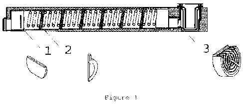
Description of the Figures
Figure 1 represents an overview of the heat exchanger
system.
Figure 2 shows an exploded view of the waste water entrance
area (drain) and valve components with a view of the
threaded support for the valve of the shower base, cover
and bucket to collect debris.
Figure 3 represents an assembly of the heat exchanger block
in the shower base.
Figure 4 represents an assembly of the block in a shower
base of a bath facility.
CA 02814611 2013-04-12
WO 2012/049637
PCT/1B2011/054506
8
Figure 5 represents an embodiment of a shower facility.
Figure 6 represents an alternative embodiment of a shower
facility with the use of a storage tank.
Figure 7 represents a turbulence flap with a crescent shape
and two half rods to fit in the turns of the coil.
Figure 8 represents the throttle plate.
Figure 9 represents the pressure mounting of the fins in
the turns of the coil.
General description of the invention
The energy recovery system is made, preferably, by a coil
usually of copper inside a PVC pipe that has at one end a
throttle plate also made of PVC, a filter protection system
against impurities, turbulence fins and an outer housing.
The energy recovery system presents a separation of the
turns of 1/3 of the diameter of the tube coil.
It is also desirable the thermal insulation through the
filling with insulating material, e.g. polyurethane, of the
inside of the casing or through the use of a box produced
in thermally insulating material, e.g. polystyrene. The
outer casing should also be made of a material that
provides mechanical strength to the assembly, e.g. a metal
CA 02814611 2013-04-12
WO 2012/049637
PCT/1B2011/054506
9
outer casing where the various parts are welded, bolted,
riveted or glued, or simply engaged. The outer casing can
also be made of rigid polystyrene that has a pressure
fitting system or clamps and does not require the use of
the previously mentioned external metal casing and
insulation.
This box inside which there is the heat exchanger system is
concealed under the floor, for example underneath a bathing
facility.
The system can be equipped with a circular impurity
retaining filter fitted at the inlet end of the PVC piping,
fit into the socket of the valve, in order to avoid
clogging problems in the pipeline in case the bucket, as a
result of an oversight or for any other reason, is not
present. This will make sure that the impurities (sand,
hair, etc.) do not go into the piping. This retention
filter has narrow passages in the form of slots that form
one or more complementary sets.
The use of a throttle at the end of the system ensures that
the tubing used is always in charge, i.e., with water
inside when in use. This way ensures that the system
retains water long enough to enable the heat transfer, and
the system has time to boost the heat recovery of the same
to the maximum. The existence of an opening at the bottom
and at the top of the throttle plate will allow the passage
of sand or other impurities that may have passed through
the first filter and that might, otherwise, create problems
or clogging of the drainage system.
CA 02814611 2013-04-12
WO 2012/049637
PCT/1132011/054506
Small fins are also used in the system interspersed in the
turns of the coil to create a turbulent regime inside the
PVC piping. The creation of this turbulent regime enhances
the amount of heat recovered. The fins are shaped like
half-moon and peripheral semi-rods that are interspersed
alternately and placed under pressure between each pair of
turns to facilitate the fitting of the same in the coil.
The fins may also have a small ledge that will serve to
maintain their position in the piping with a distance that
is maintained constant and a lower foot to support the coil
in the piping of waste water. The fins may also have a
triangular shape and two half-rods in low relief.
The cold water piping from the supply network can be
connected to the inlet collector of the coil and from the
outlet collector a connection can be made to the mixer tap
or can optionally be used a storage system through a water
heater.
The heat recovery process with the system presented herein
implies that the water that enters the collector exits the
system at a temperature t2 when compared to the environment
temperature tl (heat exchanger), in which case the
temperature t4 of the outlet of waste water is lower than
the inlet temperature t3. The water supply must leave the
outlet collector preheated and the pre-heating temperature
can go up to 28 C through the heat withdrawn from the waste
water, considering 31 C as the temperature at which the
waste water enters the system.
CA 02814611 2013-04-12
WO 2012/049637
PCT/1B2011/054506
11
The water that enters the collector (tap water) leaves the
system at a temperature t2 lower than the inlet temperature
tl (water cooling system) in which case the temperature t4
of the waste outlet is higher than the inlet temperature
t3.
The results indicate that the temperature gain when using
this system is higher than the one of the system mentioned
in the patent application PT104608 in about 30% for
comparable sizes of pipings. It is still possible to get
higher or lower temperature gains depending on the version
of the system used, in particular as regards their piping
length and/or use of the thermal insulation. This will
result in considerable savings in terms of domestic energy
consumption. On the other hand the fact that the block is
integrated into the system facilitates the assembly of the
heat recovery system on the basis of the shower or of the
bath, since the correct positioning of the components to
assemble is assured.
Preferred embodiments
In a preferred embodiment, the system is applied at the
base of a shower or at the bottom of the bath tub.
The bath water flows into the drain by the base valve of
the shower base, with most of the impurities being trapped
in the bucket or, in the absence thereof, becoming trapped
in the filter placed in the inlet end. The waste water then
passes into the piping, where the heat transfer to the coil
CA 02814611 2013-04-12
WO 2012/049637
PCT/IB2011/054506
12
(hot water from the bath) takes place. In this preferred
embodiment a PVC pipe with 0-rings and coil, 0.012 meters
in diameter and 6 meters long is used. At the end of the
piping, a throttle plate is mounted to allow the system to
have water for long enough to promote the heat transfer.
Then the waste water flows into the sewer.
The system has a coil connected to an inlet collector,
through which will go the fluid that will make the heat
recovery of the residual water of the piping. This coil is
assembled in a helical shape inside the piping. Along the
coil several fins are mounted interspersed between the
turns, in order to create a turbulent regime in the piping
in order to maximize the heat recovery. Subsequently the
water inside the coil will pass through the outlet
collector of the system to be used or to be stored in a
water heater.