Note : Les descriptions sont présentées dans la langue officielle dans laquelle elles ont été soumises.
2A 02814666 2013-04-12
WO 2012/050640
PCT/US2011/035889
APPARATUS AND METHOD FOR
LOADING AND UNLOADING CONTAINERS
BACKGROUND OF THE INVENTION
[0001] The present disclosure relates generally to a container loading and
unloading apparatus, and more particularly to an apparatus and method for
loading
and unloading containers with respect to a carrier in a controlled manner,
involving
minimum human intervention.
[0002] Containers, particularly road-transportable shipping containers, are
commonly used to ship and store cargo. Typically, the containers are loaded
into and
unloaded from a carrier, such as a shipping trailer, for transportation of the
cargo.
During the loading process, the container may be handled in an uncontrolled
manner,
resulting in unorganized arrangement of the containers, which causes waste of
the
limited space of the shipping trailer and difficulty in locating and unloading
the
containers. Furthermore, in order to organize the containers, additional human
labor
and/or equipment may be needed, for example, to place the containers in a
stacked
manner. Furthermore, the addition of the human element increases the safety
and
physiological concerns associated with manually lifting and placing shipping
cases.
[0003] U.S. Patent No. 6,725,999 to Luevano teaches an unloading system,
which includes a loading platform, a conveyor positioned below the loading
platform,
and a slanted ramp between the loading platform and the conveyor. Items to be
unloaded from a carrier can be slid from the platform to the conveyor through
the
ramp, relying on the gravity of the items. However, since the items are slid
on the
ramp, it is impossible for the system of Luevano to position a plurality of
items in a
1
2A 02814666 2013-04-12
WO 2012/050640
PCT/US2011/035889
stacked manner under control. Accordingly, interference of the items during
the
unloading process is inevitable and additional human labor is necessitated to
organize
the items.
[0004] U.S. Patent No. 5,829,947 to Litten teaches a hydraulic ramp loader,
which includes an extendible ramp and a hydraulic system for moving the ramp
up
and down with respect to a carrier. The ramp can be moved up and down by the
hydraulic system. The ramp, including four panels connected with one another,
allows an item to slide on the panels. Thus, similar to Luevano, Litten cannot
load or
unload a plurality of items in a stacked manner under control. Accordingly,
additional human labor is necessitated to organize the items.
[0005] Therefore, it is desirable to provide a container loading and
unloading
apparatus and method, which is capable of loading and unloading the containers
in a
controlled manner, and minimizing human intervention during the loading and
unloading process, thereby reducing human safety and physical concerns.
BRIEF DESCRIPTION OF THE INVENTION
[0006] As described herein, the exemplary embodiments of the current
invention overcome one or more of the above and other disadvantages known in
the
art.
[0007] An exemplary aspect of the present invention relates to an apparatus
for loading an- d unloading a plurality of items into a carrier. The apparatus
includes a
fixed staging unit, a first conveyor configured to receive and transport the
arranged
items from the fixed staging unit, a second conveyor operatively connected to
the first
conveyor, and a control unit. The plurality of items are arranged according to
a
2
2A 02814666 2013-04-12
WO 2012/050640
PCT/US2011/035889
predetermined pattern on the fixed staging unit. The first conveyor is movable
substantially horizontally. The second conveyor is configured to receive the
arranged
items from the first conveyor and transport the arranged items into the
carrier. The
second conveyor is movable substantially horizontally and vertically. The
control
unit is configured to control transportation of the arranged items from the
second
conveyor into the carrier when the second conveyor is vertically moved to a
predetermined position.
[0008] Preferably, the second conveyor includes a first end operatively
connected to the first conveyor, a second end movable substantially
vertically, and a
body connecting the first end and the second end.
[0009] Preferably, the second conveyor includes a platform disposed at the
second end thereof, for holding and substantially vertically moving the
arranged
items.
[0010] _ Preferably, the second conveyor includes an arm associated with
the
platform, for moving the arranged items from the platform into the carrier.
[0011] Preferably, the control unit is configured to move the end platform
vertically to the predetermined position based on a height of the items.
[0012] Preferably, the fixed staging unit includes a middle section and at
least
a pair of legs connected by the middle section, the middle section defining a
hollow
space therein. The fixed staging area also acts as a guide controlling the
alignment as
the conveyor unit moves forward and back during the loading or unloading
process.
3
2A 02814666 2013-04-12
WO 2012/050640
PCT/US2011/035889
[0013] Preferably, the first conveyor includes a platform section and a
frame
section, at least a portion of the platform section being received in the
hollow space of
the middle section of the fixed staging unit.
[0014] Preferably, the first conveyor includes a plurality of wheels for
assisting the substantially horizontal movement of the first conveyor.
[0015] Another exemplary aspect of the present invention relates to a
method
of loading and unloading a plurality of items into a carrier. The method
includes the
steps of arranging the plurality of items according to a predetermined
pattern, moving
the arranged items to a first conveyor, transporting the arranged items from
the first
conveyor to a second conveyor, moving the first conveyor and the second
conveyor
substantially horizontally to access a space within the carrier, moving the
second
conveyor substantially vertically to a predetermined position in the space and
moving
the arranged items from the second conveyor into the carrier.
[0016] Preferably, the step of arranging comprises arranging the plurality
of
items into a row.
[0017] Preferably, the step of moving the second conveyor substantially
vertically comprises determining a position in the space based on a height of
the items
and moving the second conveyor substantially vertically to the position.
[0018] Preferably, the steps of moving the first conveyor and the second
conveyor substantially horizontally to access a space within the carrier and
moving
the second conveyor substantially vertically to a predetermined position in
the space
are performed prior to the step of arranging the plurality of items according
to a
predetermined pattern.
4
2A 02814666 2013-04-12
WO 2012/050640
PCT/US2011/035889
[0019] Still another exemplary aspect of the present invention relates to a
method of loading and unloading a plurality of items into a carrier. The
method
includes the-steps of arranging the plurality of items into a first group and
a second
group according to a predetermined pattern, moving the first group and the
second
group to a first conveyor, transporting the first group from the first
conveyor to a
second conveyor, stopping the first conveyor, moving the first conveyor and
the
second conveyor substantially horizontally to access a space within the
carrier,
moving the second conveyor substantially vertically to a first predetermined
position
in the space, moving the first group from the second conveyor into the
carrier,
restarting the first conveyor to transport the second group from the first
conveyor to
the second conveyor, moving the second conveyor substantially vertically to a
second
predetermined position in the space, and moving the second group from the
second
conveyor into the carrier.
[0020] Preferably, the step of arranging the plurality of items into a
first group
and a second group according to a predetermined pattern comprises arranging
the
plurality of items into at least a first row and a second row.
[0021] Preferably, the step of moving the second conveyor substantially
vertically to a second predetermined position in the space comprises
determining the
second position based on a height of the items and the first predetermined
position,
and moving the second conveyor substantially vertically to the second
position.
[0022] Preferably, the method further includes moving the first conveyor
and
the second conveyor substantially horizontally after transporting the second
group
from the first conveyor to the second conveyor.
2A 02814666 2013-04-12
WO 2012/050640
PCT/US2011/035889
[0023] Preferably, the method further includes moving the first conveyor
and
the second conveyor substantially horizontally after transporting the second
group
from the second conveyor into the carrier.
[0024] Preferably, the steps of moving the first conveyor and the second
conveyor substantially horizontally to access a space within the carrier and
moving
the second conveyor substantially vertically to a first predetermined position
in the
space are performed prior to the step of arranging the plurality of items into
a first
group and a second group according to a predetermined pattern. More
preferably, the
step of moving the second conveyor substantially vertically to a second
predetermined
position in the space is performed prior to the step of restarting the first
conveyor to
transport the second group from the first conveyor to the second conveyor.
[0025] These and other aspects and advantages of the present invention
will
become apparent from the following detailed description considered in
conjunction
with the accompanying drawings. It is to be understood, however, that the
drawings
are designed solely for purposes of illustration and not as a definition of
the limits of
the invention, for which reference should be made to the appended claims.
Moreover,
the drawings are not necessarily drawn to scale and, unless otherwise
indicated, the
drawings are merely intended to conceptually illustrate the structures and
procedures
described herein.
BRIEF DESCRIPTION OF THE DRAWINGS
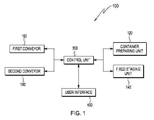
[0026] FIG. 1 is a block view of a loading and unloading apparatus
according
to an exemplary embodiment of an aspect of the present invention,
schematically
illustrating functional units of the apparatus;
6
2A 02814666 2013-04-12
WO 2012/050640
PCT/US2011/035889
[0027] FIG. 2 is a perspective view of the loading and unloading apparatus,
illustrating the detailed structures of the apparatus;
[0028] FIG. 3 is another perspective view of the loading and unloading
apparatus, illustrating movement of containers along the apparatus;
[0029] FIG. 4 is a flow chart illustrating a method of loading and
unloading a
plurality of items according to an exemplary embodiment of another aspect of
the
present invention;
[0030] FIG. 5 is a flow chart illustrating a method of loading and
unloading a
plurality of items according to another exemplary embodiment of the aspect of
the
present invention;
[0031] FIG. 6 is a flow chart illustrating a method of loading and
unloading a
plurality of items according to still another exemplary embodiment of the
aspect of
the present invention; and
[0032] FIG. 7 is a flow chart illustrating a method of loading and
unloading a
plurality of items according to yet another exemplary embodiment of the aspect
of the
present invention.
DETAILED DESCRIPTION OF THE EXEMPLARY EMBODIMENTS
OF THE INVENTION
[0033] FIG. 1 is a block view schematically illustrating functional units
of a
loading and unloading apparatus 100 according to an exemplary embodiment of
the
present invention. The apparatus 100 generally includes a container preparing
unit
120, a fixed staging unit 140, a first conveyor 160 capable of moving
substantially
7
2A 02814666 2013-04-12
WO 2012/050640
PCT/US2011/035889
horizontally, a second conveyor 180 capable of moving substantially
horizontally and
vertically, and a control unit 300. The first conveyor 160 and the second
conveyor
180 load and unload containers with respect to a carrier 200 shown in dash
lines in
FIG. 2. The carrier 200 includes, but is not limited to, a shipping trailer,
for example.
[0034] The control unit 300 is configured to communicate with the
container
preparing unit 120, the fixed staging unit 140, the first conveyor 160 and the
second
conveyor 180 to send operational instructions to the units. For example,
control
signals can be transmitted through wired or wireless communication.
[0035] During operation of the loading and unloading apparatus 100, a
plurality of shipping containers are numbered on the container preparing unit
120 and
further arranged according to a predetermined pattern on the fixed staging
unit 140.
Subsequently, the arranged containers are transported to the first conveyor
160, which
in turn transports the containers to the second conveyor 180. The control unit
300 is
configured to control transportation of the arranged items from the second
conveyor
180 into the carrier 200, after the containers are vertically moved by the
second
conveyor 180 to a predetermined position.
[0036] FIG. 2 and FIG. 3 illustrate detailed structures of the loading and
unloading apparatus 100 according to an exemplary embodiment of the present
invention.
[0037] In FIG. 2, a three-dimensional coordinate system is defined as
shown,
wherein a lateral direction is defined substantially along the X-axis, a
longitudinal
direction is defined substantially along the Y-axis and a vertical direction
is defined
substantially along the Z-axis.
8
2A 02814666 2013-04-12
WO 2012/050640
PCT/US2011/035889
[0038] The container preparing unit 120 has a support surface 122, on which
a
plurality of shipping containers can be numbered and separately transported to
the
fixed staging unit 140, as shown in FIG. 3. After a preset number of
containers are
each transported to the fixed staging unit 140 and substantially aligned in a
compact
row on the support surface 122 of the container preparing unit 120, the row of
containers are further transported to the first conveyor 160.
[0039] The operation of numbering and aligning the containers can be
implemented manually or preferably automatically by any suitable means. In the
shown embodiment, the containers are substantially cubical and thus are
aligned side-
by-side in a row substantially along the lateral direction. However, a person
of
ordinary skill in the art understands that the plurality of containers can be
arranged in
any predetermined pattern, depending on the circumstances of applying the
loading
and unloading apparatus. For example, the containers can be arranged in a
square or
arranged to have a plurality of layers. Furthermore, additional mechanism,
such as a
crane, can be used to assist the arrangement of the containers.
[0040] For example, a releasable trigger can be provided to the container
preparing unit 120. Release operations of the trigger actuate transportation
of each of
the preset number of containers onto the fixed staging unit 140 sequentially,
thereby
providing a compact row of containers on the fixed staging unit 140, as shown
in FIG.
3.
[0041] The fixed staging unit 140 is designed to be in a permanently fixed
position. The fixed staging unit 140 includes a middle section 142 and a pair
of legs
143 connected by the middle section 142. The pair of legs 143 are fixedly
connected
9
2A 02814666 2013-04-12
WO 2012/050640
PCT/US2011/035889
to the ground, and the height of the legs 143 is designed to allow smooth
transportation of the containers onto the middle section 142. For example, the
legs
143 can be configured to be adjustable to cooperate with container preparing
units
having different heights.
[0042] The middle section 142 defines a hollow space 144 therein for
accommodating at least a part of the first conveyor 160. The middle section
142 has
an upper surface 145, which can be substantially vertically aligned with the
support
surface 122 of the container preparing unit 120. The upper surface 145 can be
flat, or
slightly inclined, to assist moving the compact row of containers onto the
first
conveyor 160.
[0043] The row of containers, having a preset number of containers on the
middle section 142 of the fixed staging unit 140, can be moved to the first
conveyer
160 manually or preferably automatically. As shown in FIG. 2 and FIG. 3, the
first
conveyor 160 is configured to receive the row of containers from the fixed
staging
unit 140 and further transport the containers to the second conveyor 180.
[0044] The first conveyor 160 is capable of moving back and forth,
substantially horizontally. The first conveyor 160 includes a platform section
162 and
a frame section 164, integral or operatively connected with one another. The
platform
section 162 includes a conveying means for transporting the row of containers
from
the fixed staging unit 140 to the second conveyor 180. The conveying means
includes, but is not limited to, a series of motorized rollers, rotating belt
conveyors,
non-skid material, rubber, felt, hooks and eyes, and any combination thereof.
The
platform section 162 can be substantially flat or slightly inclined.
2A 02814666 2013-04-12
WO 2012/050640
PCT/US2011/035889
[0045] As shown, the platform section 162 further includes two pair of legs
166, each of which is provided with a wheel 168 at the lower end thereof. The
middle
portion of the platform section 162 passes through the hollow space 144
defined
within the middle section 142 of the fixed staging unit 140, which can be
realized, for
example, during the assembling process of the first conveyor 160. The hollow
space
144 and the platform section 162 are dimensioned to allow free translation of
the first
conveyor 160 under the restrain of the fixed staging unit 140.
[0046] The frame section 164 includes a pair of bars 172 projecting
substantially horizontally from the platform section 162 and a pair of legs
174
extending downwardly from the bars 172, respectively. Each of the legs 174 is
also
provided with a wheel 176 at the lower end thereof.
[0047] Provision of the wheels 166 and 176 to the platform section 162 and
the frame section 164, respectively, assists the first conveyor 160 as well as
the
second conveyor 180 to move back and forth, thereby selectively accessing the
space
within the carrier 200.
[0048] The second conveyor 180 is inclined with respect to the platform
section 162 of the first conveyor 160. The second conveyor 180 includes a
first end
182 operatively connected to the platform section 162, a second end 183 which
can be
moved substantially vertically, and a body 184 connecting the first end 182
and
second end 183.
[0049] The conveying means of the platform section 162 moves the row of
containers from the first conveyor 160 to the first end 182 of the second
conveyor
180, upon instructions from the control unit 300. After the containers are
completely
11
2A 02814666 2013-04-12
WO 2012/050640
PCT/US2011/035889
transferred to the second conveyor 180, the first conveyer 160 stops until
triggered to
advance another row of containers from the fixed staging unit 140 to the
second
conveyor 180. The first conveyor 160 will not advance another row of
containers
onto the second conveyer 180, until the second conveyor has transported the
previous
row of containers into the carriers 200 and is in a proper position to
transport an
additional row of containers into the carrier 200.
[0050] The second conveyor 180 similarly has a conveying means, which
includes, but is not limited to, a series of motorized rollers, rotating belt
conveyors,
non-skid material, rubber, felt, hooks and eyes, and any combination thereof.
[0051] As shown in FIG. 2, the second conveyor 180 includes a substantially
horizontal end platform 185 disposed at the second end 183 of the second
conveyor
180. The end platform 185 is capable of holding the row of containers after
the
containers are transported to the second end 183 and moving vertically with
the
second end 183. Furthermore, the second conveyor 180 can also be moved
vertically
to a desirable position, prior to placing the containers on the second
conveyor 180.
Thus, less energy, such as hydraulics, is needed to move the conveyor, absent
the
additional weight of the containers. The second conveyor 180 further includes
arm
186 associated with the platform 185, which moves the containers held by the
end
platform 185 into the carrier 200, under the instructions of the control unit
300.
[0052] For example, the arm 186 can be an arm movable concurrently with the
movement of the end platform 185. The arm can pivot or translate to move the
container from the platform 185 into the carrier 200. Alternatively, the arm
can
simply hold the containers as the second conveyor 180 moves back horizontally,
to
12
2A 02814666 2013-04-12
WO 2012/050640
PCT/US2011/035889
sweep the containers off the end platform 185. Alternatively, the arm can
include
vacuum heads for engaging and moving the containers. The vacuum heads can be
adjustable for selectively moving containers having difference sizes and
weights.
[0053] The second end 183 and the end platform 185 can be moved vertically
to allow rows of containers to be stacked in a column. As shown in FIG. 3,
after a
first row of containers are moved from the end platform 185 into the carrier
200, the
second end 183 and the end platform 185 are controlled to move upwardly a
distance
substantially equal to the height of the containers. At this point, it is
considered that
the second conveyor 180 is ready for placing another row of containers into
the carrier
200 and on top of the first row of containers.
[0054] Consequently, instructions are sent to the first conveyor 160 for
transporting a second row of containers to the second conveyor 180. As a
result of
moving the end platform 185 upwardly a distance substantially equal to the
height of
the containers, the second row of containers is placed by the arm 186 on top
of the
first row of containers. Subsequently, the end platform 185 moves upwardly
again a
distance substantially equal to the height of the containers, and the same
operations of
the first conveyor 160 and the second conveyor 180 repeat to stack the rows of
containers in the carrier 200, until a maximum height of the stacked
containers in one
vertical cohunn is achieved.
[0055] Once the maximum height of the stacked containers is achieved, the
first conveyor 160 is instructed to move back along the horizontal direction,
to start
new operations to achieve another vertical column of stacked containers. The
backward translation of the first conveyor 160 can be controlled to keep the
distance
13
2A 02814666 2013-04-12
WO 2012/050640
PCT/US2011/035889
between the vertical columns of stacked containers minimum, so as to utilize
the
space of the carrier 200 most efficiently.
[0056] The operations of the apparatus 100 as described above can be
reversed
to unload the containers from the carrier 200.
[0057] Referring to FIG. 1, the apparatus 100 further includes a user
interface
400. The user interface 400 allows a user to communicate with the control unit
300 to
enhance and/or expand the functions of the container preparing unit 120, the
fixed
staging unit 140, the first conveyor 160 and the second conveyor 180, under
the
control of the control unit 300. For example, a user can input through the
user
interface 400 instructions and/or parameters for instructing the container
preparing
unit 120, the fixed staging unit 140, the first conveyor 160 and the second
conveyor
180 to perform additional operations.
[0058] The control unit 300 can be implemented in a form of a computer, a
processor, or a computer readable medium having stored thereon computer
executable
instructions that, when executed by a processor of a computer, control the
processor
or computer to perform certain functions.
[0059] In the case that a plurality of containers having diverse sizes are
to be
loaded and unloaded with respect to the carrier 200, the apparatus 100
according to
the present invention is capable of providing an optimal loading/unloading
sequence
to most efficiently utilize the space of the carrier. For example, an
identifier, such as
a bar code or an RFID tag, can be printed or attached to each container. The
identifier
contains information indicating sizes and shapes of the containers. This
information
can be retrieved through suitable known means, and sent together with the
14
2A 02814666 2013-04-12
WO 2012/050640
PCT/US2011/035889
dimensional information of the carrier to the control unit 300. The control
unit 300
analyzes the information to determine which containers should be placed in the
carrier
first and which containers should be placed in the carrier subsequently,
thereby
utilizing the space of the carrier in the most efficient way.
[0060] FIG. 4 is a flow chart illustrating a method 700 for loading and
unloading a plurality of items, such as containers, into a carrier, according
to an
exemplary embodiment of another aspect of the present invention.
[0061] At step 710, a plurality of items, such as the containers shown in
FIG.
3, are arranged according to a predetermined pattern. For example, the
containers can
be arranged into a row. The step 710 can be performed on the fixed staging
unit 140
of the apparatus 100.
[0062] At step 720, the arranged items are moved to a first conveyor, for
example, the first conveyor 160 of the apparatus 100. At step 730, the
arranged items
are transported from the first conveyor to a second conveyor, for example, the
second
conveyor 180 of the apparatus 100.
[0063] At step 740, the first conveyor and the second conveyor are moved
substantially horizontally to access a space within the carrier. At step 750,
the second
conveyor, such as the second end 183 of the second conveyor 180, is moved
substantially vertically to a predetermined position in the space. At this
step, the
position can be determined based on a height of the items, and the items are
moved
substantially vertically to the position determined based on the height of the
items.
2A 02814666 2013-04-12
WO 2012/050640
PCT/US2011/035889
[0064] At step 760, the arranged items are moved from the second conveyor
into the carrier after the second conveyor is vertically moved to the
predetermined
position.
[0065] FIG. 5 is a flow chart illustrating a method 800 for loading and
unloading a plurality of items according to another exemplary embodiment of
the
aspect of the present invention.
[0066] At step 810, a first conveyor (for example, the first conveyor 160
of the
apparatus 100) and a second conveyor (for example, the second conveyor 180 of
the
apparatus 100) are moved substantially horizontally to access a space within a
carrier,
such as the carrier 200. At step 820, the second conveyor is moved
substantially
vertically to a predetermined position in the space. At this step, the
position can be
determined based on a height of the items to be conveyed by the conveyors, and
the
items are moved substantially vertically to the position determined based on
the
height of the items.
[0067] At step 830, a plurality of items, such as the containers shown in
FIG.
3, are arranged according to a predetermined pattern. For example, the
containers can
be arranged into a row. For example, the step 830 can be performed on the
fixed
staging unit 140 of the apparatus 100.
[0068] At step 840, the arranged items are moved to the first conveyor. At
step 850, the arranged items are transported from the first conveyor to the
second
conveyor. At step 860, the arranged items are moved from the second conveyor
into
the carrier after the second conveyor is vertically moved to the predetermined
position.
16
2A 02814666 2013-04-12
WO 2012/050640
PCT/US2011/035889
[0069] According to the method 800, the vertical movement of the second
conveyor is implemented prior to placing the arranged items onto the second
conveyer. Thus, the energy and hydraulics needed to move the conveyor
vertically is
reduced.
[0070] FIG. 6 is a flow chart illustrating a method 900 for loading and
unloading a plurality of items, such as containers, into a carrier, according
to still
another exemplary embodiment of the present invention.
[0071] At step 910, a plurality of items are arranged into a first group
and a
second group, according to a predetermined pattern. For example, the items can
be
arranged into at least a first row and a second row. The step 910 can be
performed on
the fixed staging unit 140 of the apparatus 100. However, a person of ordinary
skill in
the art understands that the first group and the second group can be arranged
to have
different characteristics. For example, the first group can be a row and the
second
group can be a column.
[0072] At step 920, the first group and the second group are moved to a
first
conveyor, for example, the first conveyor 160 of the apparatus 100. At step
930, the
first group is transported from the first conveyor to a second conveyor, for
example,
the second conveyor 180 of the apparatus 100. Subsequently, at step 940, the
first
conveyor is stopped.
[0073] At step 950, the first conveyor and the second conveyor are moved
substantially horizontally to access a space within the carrier. At step 960,
the second
conveyor is moved substantially vertically to a first predetermined position
in the
space. Depending on the circumstances, moving the second conveyor
substantially
17
2A 02814666 2013-04-12
WO 2012/050640
PCT/US2011/035889
vertically to a first predetermined position in the space includes keeping or
moving
the second conveyor to the ground.
[0074] At step 970, the first group is moved from the second conveyor into
the
carrier. At step 980, the first conveyor is restarted to transport the second
group from
the first conveyor to the second conveyor.
100751 At step 990, the second conveyor is moved substantially vertically
to a
second predetermined position in the space. This step includes determining the
second position based on a height of the containers and the first
predetermined potion,
and moving the second conveyor substantially vertically to the second
position. At
step 992, the second group is moved from the second conveyor into the carrier.
[0076] The method can further include moving the first conveyor and the
second conveyor substantially horizontally after transporting the second group
from
the first conveyor to the second conveyor.
[0077] The method can further include moving the first conveyor and the
second conveyor substantially horizontally after transporting the second group
from
the second conveyor into the carrier. For example, after the first row and the
second
row of containers are stacked into the carrier. The conveyors can be moved
horizontally to allow forming another stack of containers in the carrier.
[0078] FIG. 7 is a flow chart illustrating a method 1000 for loading and
unloading a plurality of items, such as containers, into a carrier, according
to yet
another exemplary embodiment of the present invention.
[0079] At step 1010, a first conveyor and a second conveyor are moved
substantially horizontally to access a space within a carrier. At step 1020,
the second
18
2A 02814666 2013-04-12
WO 2012/050640
PCT/US2011/035889
conveyor is moved substantially vertically to a first predetermined position
in the
space. Depending on the circumstances, moving the second conveyor
substantially
vertically to a first predetermined position in the space includes keeping or
moving
the second conveyor to the ground.
[0080] At step 1030, a plurality of items are arranged into a first group
and a
second group, according to a predetermined pattern. For example, the items can
be
arranged into at least a first row and a second row. However, a person of
ordinary
skill in the art understands that the first group and the second group can be
arranged to
have different characteristics. For example, the first group can be a row and
the
second group can be a column.
[0081] At step 1040, the first group and the second group are moved to the
first conveyor. At step 1050, the first group is transported from the first
conveyor to
the second conveyor. Subsequently, at step 1060, the first conveyor is
stopped. At
step 1070, the first group is moved from the second conveyor into the carrier.
[0082] At step 1080, the second conveyor is moved substantially vertically
to
a second predetermined position in the space. This step includes determining
the
second position based on a height of the items and the first predetermined
potion, and
moving the second conveyor substantially vertically to the second position. At
step
1090, the first conveyor is restarted to transport the second group from the
first
conveyor to the second conveyor. At step 1100, the second group is moved from
the
second conveyor into the carrier.
[0083] According to the method 1000, the vertical movement of the second
conveyor is implemented prior to placing the first group and the second group
onto
19
2A 02814666 2013-04-12
WO 2012/050640
PCT/US2011/035889
the second conveyer. Thus, the energy and hydraulics needed to move the
conveyor
vertically is reduced.
[0084] The method can further include moving the first conveyor and the
second conveyor substantially horizontally after transporting the second group
from
the first conveyor to the second conveyor.
[0085] The method can further include moving the first conveyor and the
second conveyor substantially horizontally after transporting the second group
from
the second conveyor into the carrier. For example, after the first row and the
second
row of containers are stacked into the carrier. The conveyors can be moved
horizontally to allow forming another stack of containers in the carrier.
[0086] The loading and unloading apparatus and method according to the
exemplary embodiments of the present invention are capable of automatically
loading
and unloading shipping containers with respect to, for example, a shipping
trailer with
minimum human intervention. Thus, the loading and unloading efficiency is
improved. Furthermore, by configuring the control unit, the loading and
unloading
apparatus is capable of determining an optimal sequence for loading the
containers
into the carrier. Thus, the limited space of the carrier can be utilized most
efficiently.
[0087] Although the loading and unloading apparatus and method according
to the present invention has been described with respect to loading and
unloading
containers commonly used for shipping purpose, a person of ordinary skill in
the art
understands that the apparatus and method according to the present invention
can be
used to load and unload a wide variety of items, articles and objects.
2A 02814666 2013-04-12
WO 2012/050640
PCT/US2011/035889
[0088] The features of the present invention as applied to various specific
embodiments thereof have been shown and described. It will also be understood
that
various omissions, substitutions and changes in the form and details of the
devices
illustrated and in their operation, may be made by those skilled in the art
without
departing from the spirit of the invention. For example, it is expressly
intended that
all combinations of those elements and/or method steps which perform
substantially
the same function in substantially the same way to achieve the same results
are within
the scope of the invention. Moreover, it should be recognized that structures
and/or
elements and/or method steps shown and/or described in connection with any
disclosed form or embodiment of the invention may be incorporated in any other
disclosed or described or suggested form or embodiment as a general matter of
design
choice. It is the intention, therefore, to be limited only as indicated by the
scope of
the claims appended hereto.
21