Note : Les descriptions sont présentées dans la langue officielle dans laquelle elles ont été soumises.
CA 02814936 2013-05-08
BOGIE AND SIDE FRAME THEREOF
FIELD OF THE INVENTION
[0001] The present application relates to the field of transportation
facilities, and
particularly to a bogie and a side frame thereof.
BACKGROUND OF THE INVENTION
[0002] The bogie is one of the most important components in the structure of
the
railway vehicle, it is mainly used to increase the carrying capacity, the
length and the volume
of the vehicle, and to increase the speed of the vehicle, such that the
vehicle can have a good
operation quality when it is run at a low or high speed under a specified
railway track so as to
protect the vehicle and the goods, satisfying requirements for the development
of railway
transportation. The bogie may be divided into a frame type bogie, a quasi-
frame type bogie
and a three-piece bogie in terms of the load transforming manner between the
vehicle body
and the bogie.
[0003] Referring to Figures 1 to 3, Figure 1 and Figure 2 are a front view and
a top view of
a side frame of a three-piece bogie in the prior art, respectively; and Figure
3 is a structural
schematic view of a supporting seat in Figure 1. Operation processes of the
above bogie and
its drawbacks will be briefly explained hereinafter.
[0004] In the prior art, as shown in Figures 1 to 3, the above side frame is
applicable to a
central cross-braced bogie, that is, the bogie includes a first connecting rod
and a second
connecting rod passed through holes provided on two sides of the abdominal
portion of the
bolster in a cross manner, and each of two side frames thereof is
symmetrically provided with
two supporting seats 1'. During the operation, the two supporting seats 1' of
the first side
frame are connected to the first end of the first connecting rod and the first
end of the second
connecting rod, respectively, and the two supporting seats 1' of the second
side frame are
connected to the second end of the first connecting rod and the second end of
the second
connecting rod, respectively, so as to form the central cross-bracing
structure and avoid a
parallelogram phenomenon among the two side frames and two pairs of wheels.
Therefore,
the curving performance is improved and the critical speed of the hunting
motion is increased.
[0005] However, the supporting seat 1' on the above side frame includes a
supporting plate
- 1 -
CA 02814936 2013-05-08
11' which is arranged horizontally and a first vertical plate 12' and a second
vertical plate 13'
which are arranged vertically. The three plates are welded onto the side frame
after being
welded together. This kind of side frame has a high requirement on the welding
process and a
high dependence on the welding quality. A large deformation may be caused by
welding,
which generally results in a low installation precision of the side frame, and
thus a poor
strength of the side frame, which thereby affects the motion reliability of
the bogie.
[0006] In view of the technical drawbacks in the prior art, there is an urgent
demand to
further improve the side frame of the bogie to increase the installation
precision of the side
frame and enhance the motion reliability of the bogie.
SUMMARY OF THE INVENTION
[0007] An object of the present application is to provide a side frame for a
bogie so as to
increase the installation precision of the side frame and enhance the motion
reliability of the
bogie. On basis of this, another object of the present application is to
provide a bogie having
the side frame.
[0008] In order to solve the above technical problem, it is provided according
to the present
application a side frame for a bogie. The bogie includes a bolster provided
between two side
frames. The bogie further includes two connecting rods passed through holes on
two sides of
an abdominal portion of the bolster in a cross manner. Two longitudinal sides
of each side
frame are respectively provided with a supporting seat for connecting an end
portion of the
connecting rod, and the supporting seat is integrally formed with the side
frame by casting.
The supporting seat includes a supporting plate, a middle rib provided
underneath a middle
portion of the supporting plate, and a first side rib provided underneath a
longitudinal inner
side of the supporting plate. The supporting plate is provided, on a middle
portion thereof,
with a through hole. The connecting rod and the supporting seat are thread-
connected via a
conical pole which is fixedly provided in the through hole.
[0009] Preferably, the supporting plate is tapered along its length from its
root portion to its
end portion; and the first side rib has the same extending direction as that
of a longitudinal
inner side of the supporting plate, and is supported under an edge of the
longitudinal inner
side of the supporting plate.
[0010] Preferably, the extending direction of the longitudinal inner side of
the supporting
plate and the extending direction of the first side rib are parallel with a
direction of the
- 2 -
CA 02814936 2013-05-08
connecting rod connected to the supporting seat.
[0011] Preferably, the end portion of the supporting plate is provided with a
round plate,
and the through hole is provided on the round plate.
[0012] Preferably, a bottom surface of the middle rib and a bottom surface of
the first side
rib are inclined surfaces.
[0013] Preferably, the supporting seat is provided at a transverse outer side
or a transverse
inner side of the side frame, or is provided at an upper side or a lower side
of the side frame.
[0014] Preferably, the bogie further includes a cross beam extended across the
two side
frames, and an upper end portion of each side frame is provided with a bracket
which is
connected to an end portion of the cross beam.
[0015] Preferably, the bracket includes a horizontal plate and vertical plates
provided at two
sides of the horizontal plate, and the bracket is integrally formed with the
side frame by
casting.
[0016] The present application provides a side frame for a bogie. Two
longitudinal sides of
the side frame are respectively provided with a supporting seat for connecting
an end of a
connecting rod, and the supporting seat is integrally formed with the side
frame by casting.
The supporting seat includes a supporting plate, a middle rib provided
underneath a middle
portion of the supporting plate, and a first side rib provided underneath a
longitudinal inner
side of the supporting plate. A middle portion of the supporting plate is
provided with a
through hole, and the connecting rod is thread-connected to the supporting
seat via a conical
pole which is fixedly provided in the through hole.
[0017] With such a structure, in the operation of the bogie, since the
supporting seat is
integrally formed with the side frame by casting, errors caused by welding
distortion in the
prior art is avoided, welding processes are reduced, the installation
precision of the supporting
seat is ensured and the strength of the supporting seat 1 is enhanced, thereby
the motion
reliability of the side frame is relative high. The side frame having the
above structure can
also reduce the production cost of the side frame. For a central cross-braced
bogie, since the
two connecting rods are crossed at a middle position between the two side
frames and are
connected with supporting seats 1 of the side frame, a middle portion of and
the longitudinal
inner side of the supporting seat 1 may be subject to greater forces in the
operation of the
-3 -
CA 02814936 2013-05-08
bogie. With the above structure, the supporting plate 11 can be supported, at
the main stressed
portions thereof, by the middle rib 12 and the first side rib 13, therefore
the strength and
operation reliability of the supporting seat 1 are enhanced. Moreover, since
the connecting rod
and the supporting seat 1 are connected via threads and the conical pole, the
connection
reliability of the connecting rod can be ensured, and processes of assembling
and
disassembling are simple and convenient.
[0018] The present application further provides a bogie including two pairs of
wheels, two
side frames provided on two transverse sides of the two pairs of wheels and a
bolster mounted
between the two side frames, among which the side frame is the side frame as
described
above.
[0019] Since the above mentioned side frame can provide the above technical
effects, the
bogie including the side frame can also provide the same technical effects,
the description of
which is therefore omitted for simplicity.
BRIEF DESCRIPTION OF THE DRAWINGS
[0020] Figure 1 is a front view of a side frame of a three-piece bogie in the
prior art;
[0021] Figure 2 is a top view of Figure 1;
[0022] Figure 3 is a structural schematic view of a supporting seat in Figure
1;
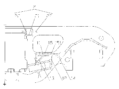
[0023] Figure 4 is a front view of a side frame according to an embodiment of
the present
application;
[0024] Figure 5 is a top view of Figure 4; and
[0025] Figure 6 is a left view of Figure 4.
[0026] Correspondence relationships between reference numerals in Figures 1 to
3 and the
components are as follows:
l' supporting seat; 11' supporting plate; 12' first vertical plate;
13' second vertical plate; 14' conical pole; and
correspondence relationships between reference numerals in Figures 4 to 6 and
the
components are as follows:
1. supporting seat, 11. supporting plate, 12. middle rib,
- 4 -
CA 02814936 2013-05-08
121. bottom surface of the middle rib, 13. first side rib,
131. bottom surface of the first side rib, 14. second side rib; 15. round
plate,
151. through hole, 2. bracket, 21. horizontal plate, 22. vertical plate.
DETAILED DESCRIPTION OF THE INVENTION
[0027] An aspect of the present application is to provide a side frame for a
bogie. The side
frame is integrally formed thereon with a supporting seat by casting, thereby
the installation
precision and strength of the side frame is improved, and thus the motion
reliability of the
bogie is improved. On basis of this, another aspect of the present application
is to provide a
bogie with the above side frame.
[0028] In order to facilitate those skilled in the art to better understand
technical solutions of
the present application, the present application will be explained in detail
in conjunction with
the accompanying drawings and the embodiments.
[0029] It is to be noted that noun of locality "longitudinal" and "transverse"
used herein
refer to the length direction and the width direction of the track when the
bogie is parked on a
railway track, respectively. That is, herein, the term "longitudinal" refers
to the direction in
Figure 4 extended from left to right, the term "transverse" refers to the
direction in Figure 4
extended perpendicular to the paper; the term "longitudinal inner side" and
"longitudinal outer
side" refer to the left side and the right side in Figure 4, respectively; and
the term "transverse
inner side" and "transverse outer side" refer to the upper side and the lower
side in Figure 5,
respectively. It shall be appreciated that the noun of locality is defined
based on the
accompanying drawings, which should not be construed as a limitation to the
protection scope
of the present application.
[0030] Referring to Figures 4 to 6, Figure 4 is a front view of a side frame
according to an
embodiment of the present application; Figure 5 is a top view of Figure 4; and
Figure 6 is a
left view of Figure 4.
[0031] As shown in Figures 4 to 6, it is provided according to an embodiment
of the present
application a side frame which is mainly applicable to a central cross-braced
bogie. The
central cross-braced bogie includes two pairs of wheels, two side frames are
provided on two
transverse sides of the two pairs of wheels, and a bolster is connected
between the two side
-5 -
CA 02814936 2013-05-08
=
frames. The bogie further includes two connecting rods which are passed
through holes on
two sides of the abdominal portion of the bolster in a cross manner, and each
of two
longitudinal sides of the side frame is provided with a supporting seat 1
which is integrally
formed with the side frame by casting for connecting ends of the connecting
rods. The two
connecting rods and the supporting seat 1 constitute the central cross-bracing
structure of the
bogie, which acts as a supporting component for the bogie during the operation
of the bogie,
so as to avoid a parallelogram phenomenon among the two side frames and the
two pairs of
wheels. As shown in Figures 4 and 5, the supporting seat 1 may include a
supporting plate 11,
a middle rib 12 provided underneath a middle portion of the supporting plate
11, and a first
side rib 13 provided under a longitudinal inner side of the supporting plate
11. The supporting
plate 11 is provided with a through hole 151 at a middle position thereon, and
the connecting
rod is thread-connected to the supporting seat 1 through a conical pole
provided in the through
hole 151.
[0032] With such a structure, in the operation of the bogie, since the
supporting seat 1 is
integrally formed with the side frame by casting, errors caused by welding
distortion in the
prior art can be avoided, welding processes are reduced, installation
precision of the
supporting seat 1 is ensured and strength of the supporting seat 1 is
enhanced, thereby the
bogie has a high motion reliability. Furthermore, through calculation,
compared with a
supporting seat 1 provided by welding, the supporting seat 1 integrally formed
by casting can
lower the cost by 200 Yuan, and the weight can be reduced by 10kg, thus the
cost is further
reduced by 150 Yuan. In this way, the side frame having the above structure
can reduce the
production cost of the side frame. For a central cross-braced bogie, since the
two connecting
rods are crossed at a middle position between the two side frames and are
connected to the
supporting seats 1 of the side frame, the middle portion and the longitudinal
inner side of the
supporting seat 1 suffer larger forces in the operation of the bogie. With the
above structure,
the supporting plate 11 can be supported by the middle rib 12 and the first
side rib 13 at main
stressed portions of the supporting seat 1, therefore strength and operation
reliability of the
supporting seat 1 are enhanced. Moreover, the connecting rod is thread-
connected to the
supporting seat 1 via the conical pole, which can ensure the connection
reliability of the
connecting rod, and processes of assembling and disassembling are simple and
convenient.
[0033] It is expected that the supporting seat is not limited to the above
structure. For
example, in order to further enhance the strength of the supporting seat 1, a
second side rib 14
- 6 -
CA 02814936 2013-05-08
may be further provided under a longitudinal outer side of the supporting seat
1; and the
connecting rod may be connected to the supporting seat 1 in connection manners
other than
the conical pole.
[0034] The structure of the above supporting seat 1 may be further configured.
[0035] In another embodiment, the supporting plate 11 is tapered along its
length from its
root portion to its end portion. The first side rib 13 has the same extending
direction as that of
the longitudinal inner side of the supporting plate 11, and the first side rib
13 is supported
under an edge of the longitudinal inner side of the supporting plate 11.
[0036] With such a structure, the supporting plate 11 having a shape varied
along the length
and the first side rib 13 facilitate the casting process of the supporting
seat 1 and the side
frame. Since the extending direction of the supporting plate 11 is coincided
with that of the
first side rib 13, the strength and operation reliability of the supporting
seat 1 is further
ensured.
[0037] Based on the above solutions, the extending direction of the
longitudinal inner side
of the supporting plate 11 and the extending direction of the first side rib
13 are parallel with
the direction of the connecting rod connected to the supporting seat 1. In
this way, a direction
of a force exerted on the side frame by the connecting rod is substantially
parallel with a
declined direction of the supporting plate 11, resulting in that the force
exerted on the side
frame by the supporting seat 1 being more reasonable, and it further prevents
the supporting
seat 1 from being damaged because of being pulled for a long term, thereby the
service life of
the supporting seat 1 is prolonged.
[0038] In a further solution, the end portion of the supporting plate 11 is
provided with a
round plate 15, and the through hole 151 for mounting the conical pole is
provided on the
round plate 15.
[0039] With such a structure, the round plate 15 has a shape substantially the
same with a
shape of a bottom surface of the conical pole mounted on the supporting plate,
which
facilitates to improve the supporting reliability of the supporting seat 1 for
the conical pole. Of
course, the end portion of the supporting plate 11 may have other shapes such
as rectangle,
square and the like.
[0040] In another embodiment, a bottom surface 121 of the middle rib 12 and a
bottom
- 7 -
CA 02814936 2013-05-08
surface 131 of the first side rib 13 are both inclined surfaces.
[0041] With such a structure, compared with the structure of the prior art in
which each of
the bottom surface of the middle rib 12 and the bottom surface of the first
side rib 13 includes
two inclined surfaces, the middle rib 12 and the first side rib 13, each of
which has one
inclined surface, have simpler and smoother curves, which further facilitates
the casting
process and in which the exerted force is reasonable.
[0042] In another embodiment, the supporting seat 1 may be provided at a
transverse outer
side or a transverse inner side of the side frame. The supporting seat 1 may
also be provided at
an upper side or a lower side of the side frame.
[0043] The supporting seats 1 provided at various positions as mentioned above
can achieve
the connection between the connecting rod and the side frame, thereby the
motion reliability
of the bogie is ensured. The user may make a choice according to actual needs.
[0044] In another embodiment, the bogie further includes a cross beam extended
across the
two side frames, and an upper end portion of each side frame is provided with
a bracket 2
which is connected to an end of the cross beam for supporting the cross beam,
and thus the
operation stability of the side frame is further enhanced.
[0045] The bracket 2 includes a horizontal plate 21 and vertical plates 22
provided at two
sides of the horizontal plate 21. The bracket 2 is integrally formed with the
side frame by
casting.
[0046] Similar to technical effects of the supporting seat 1 integrally formed
by casting, the
bracket 2 integrally formed by casting can enhance the strength of the bracket
2 and ensure
the installation precision of the bracket 2, thus improving the motion
reliability of the bogie.
[0047] It is further provided according to the present application a bogie
including two pairs
of wheels, two side frames provided on two sides of the two pairs of wheels
and a bolster
mounted between the two side frames, among which the side frame is the side
frame as
described above.
[0048] Since the above mentioned side frame can provide the above technical
effects, the
bogie including the side frame can also provide the same technical effects,
the description of
which is therefore omitted for simplicity.
[0049] A bogie and a side frame thereof provided according to the present
application are
- 8 -
CA 02814936 2014-11-25
described in detail in the above. Herein, specific examples are employed to
explain the
principle and embodiments of the present application. The description of the
above
embodiments is only used to facilitate the understanding of the method of the
present
application and the idea thereof.
- 9 -