Note : Les descriptions sont présentées dans la langue officielle dans laquelle elles ont été soumises.
CA 02815653 2013-05-13
1
CATIIETER WITH HELICAL END SECTION FOR VESSEL ABLATION
CROSS-REFERENCE TO RELATED APPLICATION
This application claims the benefit of U.S. Provisional Patent Application
61/646,688, filed May
14, 2012, which is incorporated herein by reference.
FIELD OF INVENTION
[00011 This invention relates generally to methods and devices for invasive
medical
treatment, and specifically to catheters, in particular, catheters having
distal sections adapted for
mapping and/or ablating selected vessel anatomy. More specifically, this
invention relates to a
catheter for ablating nerves and other tissue in a vessel such as a renal
artery, pulmonary vein or
other tubular vessel.
BACKGROUND
[00021 Ablation of myocardial tissue is well known as a treatment for
cardiac arrhythmias.
In radio-frequency (RF) ablation, for example a catheter is inserted into the
heart and brought
into contact with tissue at a target location. RF energy is then applied
through an electrode on
the catheter in order to create a lesion for the purpose of breaking current
conduction paths in the
tissue.
[00031 Additionally, the use of renal neurostimulation for the
treatment of heart arrhythmias
was disclosed in U.S. Patent Publication No. 2007/1029671 by Demaris et al.
Demaris sets forth
the use of neuromodulation to effectuate irreversible electroporation or
electrofusion, ablation,
necrosis and/or inducement of apoptosis, alteration of gene expression, action
potential
attenuation or blockade, changes in cytokine up-regulation and other
conditions in target neural
fibers. In some embodiments, such neuromodulation is achieved through
application of
neuromodulatory agents, thermal energy, or high intensity focused ultrasound.
-1-
CA 02815653 2013-05-13
1
[0004] In U.S. Patent Publication No. 2010/0222851 by Deem et al. the
monitoring of renal
neuromodulation was proposed stimulation to identify renal nerves to denervate
or modulate.
Stimulation of such nerves after prior to neural modulation would be expected
to reduce blood
flow while stimulation after neural modulation would not be expected to reduce
blood flow to
the same degree when utilizing similar situation parameters and locations
prior to neural
modulation.
[0005] Recently, circumferential ablation of the pulmonary vein has gained
acceptance as a
treatment for atrial arrhythmias, and particularly for atrial fibrillation.
For example, U.S. Patent
6,064,902, whose disclosure is incorporated herein by reference, describes a
catheter for ablating
tissue on the inner wall of a blood vessel, such as a pulmonary vein. The tip
portion of the
catheter is deflectable from a first, generally straight, configuration, in
which the proximal and
distal sections are substantially co-linear, to a second, J-shaped,
configuration in which the
proximal and distal sections are generally parallel with a separation
therebetween substantially
corresponding to the inside diameter of the blood vessel. The distal end
portion of the catheter is
rotated about the longitudinal axis of the catheter to cause a circumferential
displacement of
proximal and distal ablation electrodes on the catheter along the inner wall
of the pulmonary
vein. In this way, the electrode catheter may be used to ablate a number of
circumferentially-
spaced sites on the inner wall of the pulmonary vein by ablating one or two
sites at each
circumferential position.
[0006] U.S. Patent Application Publication 2005/0033135, whose disclosure
is incorporated
herein by reference, describes a lasso for pulmonary vein mapping and
ablation. A catheter for
circumferentially mapping a pulmonary vein (PV) includes a curved section
shaped to generally
-2-
CA 02815653 2013-05-13
1
conform to the shape of the interior surface of the PV. The curved section is
connected to
catheter by a generally straight axial base section that is in an "on edge"
configuration where the
base axial section connects to the curved section on the circumference of the
curved section. The
curved section comprises one or more sensing electrodes, and its proximal end
is joined at a
fixed or generally known angle to a base section of the catheter. Position
sensors are fixed to the
curved section of the catheter and to the distal end of the base section. The
catheter is inserted
into the heart, and the curved section is positioned in contact with the wall
of the PV, while the
base section remains within the left atrium, typically positioned such that
the joint with the
curved section is at the ostium of the vein. The information generated by the
three position
sensors is used to calculate the locations and orientations of the sensing
electrodes, which
enables mapping of the surface of the PV. The sensing electrodes may
additionally perform
ablation of selected sites, or the catheter may further comprise ablation
elements.
[0007] U.S. Patent Application No. 12/345,720, which is assigned to
the assignee of the
present patent application and whose disclosure is incorporated herein by
reference, describes an
alternative design in which the lasso is thicker and stiffer. Even so,
operators can find lasso
catheters to be difficult to maneuver within the heart and position in such a
way that the entire
circumference of the lasso is in contact with the tissue, as is desirable for
effective pulmonary
vein isolation.
[0008] U.S. Patent Application No. 13/174,742, which is assigned to
the assignee of the
present application and whose disclosure is incorporated herein by reference,
describes a design
which is adapted for use at the ostia or wall outside the vessel.
-3-
CA 02815653 2013-05-13
1
[0009] However, because human anatomy varies between individuals, the
shape and size of a
vessel such as a renal artery or a pulmonary vein vary, and the end section
whether having an
arcuate shape or a generally helical shape may not always fit the particular
target ostium.
Because of these factors, contact between the electrodes and the vessel wall
is often less than
complete and an ablation which effectively blocks conduction through the
nerves in the vessel
wall may not be complete. Accordingly, a desire exists for a catheter for
ablation in a vessel
which has a helical design so as to enable such an ablation in a vessel such
as a renal artery or
pulmonary vein.
SUMMARY OF THE INVENTION
[0010] The present invention is directed to a catheter whose distal
assembly has a helical
shape whose configuration that can either be static in diameter once deployed
from or sheath or
which in some embodiments be varied by means of a contraction wire actuated by
a control
handle and/or the use of a mandrel that is inserted into the distal assembly.
For improved surface
contact between the electrodes and the target tissue, e.g., a pulmonary vein
or renal artery, the
distal assembly includes a radially transverse section that supports the
electrode-bearing curved
portion of the distal assembly.
[0011] The configuration of the electrode-bearing portion of the
distal assembly is generally
curved or circular, including a helical form or a crescent shape, for mapping
and/or ablating
tubular regions, such as a pulmonary vein. The helical form may be tapered,
either expanding in
radius or decreasing in radius along its spiral or have a generally consistent
diameter along its
length. A support member with shape memory provides the desired configuration
in the distal
assembly and its flexibility can vary along its length. For example, the
helical form may be
stiffer in the proximal portion for withstanding load and more flexible in the
distal portion for
-4-
CA 02815653 2013-05-13
1
easier contraction. Such variable stiffness can be accomplished by varying the
thickness of the
support member, such as having a thicker proximal portion and a thinner distal
portion.
[0012] To minimize the risk of charring, ablation ring electrodes carried
on the distal
assembly are irrigated. The ablation ring electrode has an enlarged mid-
section so as to provide
an annular gap or reservoir around the tubing carrying the ring electrode so
that flow distribution
to outside the electrode through apertures in the side wall of the ablation
ring electrode is
improved. Apertures are also provided in opposing end portions of the ring
electrodes so that
irrigation flows in the radial direction, as well as in the axial direction.
[0013] In a variable diameter configuration, a contraction wire can be
actuated via the
control handle to contract the distal assembly or a mandrel can be inserted
through the distal
assembly, or in particular, through the support member, to vary or alter the
form of the electrode-
bearing curved portion of the distal assembly. To facilitate this adjustment
or variation, the
support member can be hollow so as to receive the mandrel therethrough. To
increase flexibility
of the support member so that it can yield to the predetermined form of the
mandrel while
maintaining sufficient rigidness so that it can return its own predetermined
form in the absence
or withdrawal of the mandrel, the support member may be formed from a bundle
of wires coiled
in a spiral, or it may be a tubular member with a spiral cut along its length.
The spiral cut may
be smooth, or it may have an interlocking pattern such that the support member
provides the
desired flexibility without elongation in the axial direction.
[0014] The electrode-bearing portion of the distal assembly may
include smaller and/or more
closely spaced-together ring electrodes for impedance and/or PV potential
recording.
Accordingly, a single catheter can perform simultaneous ablation, mapping
(electrogram
recording) and assessment of tissue contact.
[0015] In one embodiment, the catheter includes an elongated body and
a distal assembly
with a shape-memory member defining a generally helical form. The catheter
further includes a
-5-
CA 02815653 2013-05-13
control handle adapted to actuate a deflection puller wire for deflecting a
portion of the elongated
body, and a contraction wire for contracting the generally helical form. The
generally helical
form which carries at least one ring electrode has an off-edge configuration
relative to the
elongated body such that a longitudinal axis of the elongated body does not
intersect the
circumference of the helical form and the generally helical form spirals about
the longitudinal
axis of the elongated body. Moreover, the helical form can have an on-axis
configuration such
that the longitudinal axis of the elongated body is axially aligned with a
central longitudinal axis
of the helical form, or an off-axis configuration such that these axes are
axially offset from each
other.
[0016] In a more detailed embodiment, the catheter has a distal
assembly with a helical form
carrying a plurality of irrigated ablation ring electrodes and a plurality of
smaller ring electrodes
adapted for impedance recording or PV potential recording. A control handle
has a first control
member that draws a contraction wire for contracting the helical form, and a
second control
member that draws a deflection wire for deflecting an intermediate section
proximal of the distal
assembly. A support member with shape memory extends through the distal
assembly to provide
the helical form. The support member has a varying stiffness along its length,
for example, a
decreasing stiffness toward a distal end of the support member.
[0017] In another more detailed embodiment, the support member is hollow so
that it can
receive a mandrel whose stiffness is greater than that of the support member
so that the support
member can yield to and generally assume the predetermined form of the
mandrel. The support
member may be of a hollow strand tube construction, or it may be a tubular
construction with a
spiral cut with either a smooth pattern or an interlocking pattern.
[00181 In a further embodiment, the helical section has a diameter which is
sized so as to
provide sufficient apposition to the walls of the lumen without requiring a
contraction wire to
vary its size. This embodiment provides a lower cost, easy to manufacture
alternative to the
-6-
CA 02815653 2013-05-13
1
contractible assembly. The control handle in the embodiment provides a means
to manipulate
the catheter and to house a connector and electrical connections as well as an
irrigation luer and
lumen to provide irrigation fluid to the distal end.
BRIEF DESCRIPTION OF THE DRAWINGS
[0019] These and other features and advantages of the present
invention will be better
understood by reference to the following detailed description when considered
in conjunction
with the accompanying drawings. It is understood that selected structures and
features have not
been shown in certain drawings so as to provide better viewing of the
remaining structures and
features.
[0020] FIG. 1 is a top plan view of an embodiment of a catheter in
accordance with the
present invention.
[0021] FIG. 2 is a side view of an embodiment of a distal end portion of a
catheter of the
present invention, including a distal assembly.
[0022] FIG. 3 is a perspective view of an embodiment of a distal
assembly.
[0023] FIG. 4 is a perspective view of a distal assembly of a catheter
in accordance with the
present invention.
[0024] FIG. 5A is a side cross-sectional view of the catheter of FIG. 1,
taken along line J--J.
[0025] FIG. 5B is a side cross-sectional view of the catheter of FIG.
1, taken along line K--
K.
[0026] FIG. 6 is an end cross-sectional view of the catheter of FIG.
1, taken along line H--H.
[0027] FIG. 7 is a side cross-sectional view of a section of the
distal end portion of FIG. 1, as
delineated by line E--E.
[0028] FIG. 8A is an end view of a first embodiment of a distal
assembly, with an off-edge,
on axis configuration.
-7-
CA 02815653 2013-05-13
1
[0029] FIG. 8B is an end view of a second embodiment of a distal
assembly, with an off-
edge, on axis configuration.
[0030] FIG. 8C is an end view of a third embodiment of a distal assembly,
with an off-edge,
off axis configuration.
[0031] FIG. 9 is an end cross-sectional view of a section of the
distal end portion of FIG. 3,
taken along line C--C.
[0032] FIG. 10 is a side cross-section view of a distal tip of the
distal end portion of FIG. 2,
taken along line D--D.
10033] FIG. 11 is a perspective view of an embodiment of an irrigated
ablation electrode.
100341 FIG. 12 is a cross-sectional view of the irrigated ablation
electrode of FIG. 11
[0035] FIG. 13 is a perspective view of an embodiment of an irrigated
ablation electrode.
[0036] FIG. 14 is a side cross-sectional view of a portion of an
embodiment of a distal
assembly carrying an irrigated ablation electrode.
[0037] FIG. 15 is a side cross-sectional view of the control handle of
FIG. 1, taken along line
L--L.
[0038] FIG. 16 is a partial detailed view of the control handle of
FIG. 16.
[0039] FIG. 17A is a side perspective view of a first embodiment of a
hollow shape-memory
support member.
[0040] FIG. 17B is a side perspective view of a second embodiment of a
hollow shape-
memory support member.
[0041] FIG. 17C is a side perspective view of a third embodiment of a
hollow shape-memory
support member.
[0042] FIG. 18 is a schematic pictorial illustration of a system for
ablation of tissue in the
heart, in accordance with an embodiment of the present invention.
-8-
CA 02815653 2013-05-13
1
[0043] FIG. 19 is a schematic sectional view of a heart showing
insertion of a catheter into
the left atrium and the pulmonary vein, in accordance with an embodiment of
the present
invention.
[0044] FIGS. 20 and 21 are pictorial representation of the renal
anatomy showing insertion
of the catheter into the renal artery.
[0045] FIG. 22 is a perspective view of the distal assembly of a
catheter in accordance with
the present invention.
[0046] FIG. 23 is a cross-section of the distal assembly of FIG. 22 through
line M-M.
[0047] FIG. 24 A is a side view of an additional embodiment of the
present invention having
a helical distal end portion for treatment of vessels.
[0048] FIG. 24B is a cross-sectional view of a proximal portion of
FIG. 24A through line N-
N.
[0049] FIGS. 25A and 25B are a side view and partially transparent side
view of the
electrode bearing portion of the distal assembly of the embodiment of FIG.
24A.
[0050] FIG. 26 A is a perspective view of the distal assembly of the
embodiment of FIG.
24A.
[0051] FIG. 26B is a cross-sectional view of the distal assembly of
FIG. 26A taken through
line 0-0.
[0052] FIG. 26C is a cross-sectional view of the distal assembly of
FIG. 26A taken through
line P-P.
[0053] FIG. 26D is a cross-sectional view of the distal assembly of
FIG. 26A taken through
line Q-Q.
[0054] FIG. 27 is a cross-sectional view of FIG. 25B through line R-R.
-9-
CA 02815653 2013-05-13
1
DETAILED DESCIPTION OF THE INVENTION
[0055] Referring to FIGS. 1-4, a catheter 10 according to the
disclosed embodiments
comprises an elongated body that may include an insertion shaft/catheter body
12 having a
longitudinal axis, and an intermediate section 14 distal of the catheter body
that can be uni- or bi-
directionally deflected off axis from the catheter body longitudinal axis. A
resilient three-
dimensional distal assembly 17, with ring electrodes 19 disposed along a
nonlinear or curved
distal portion, extends from a generally straight transitional section 20
distal of the elongated
body or the intermediate section 14. In accordance with a feature of the
present invention, the
curved distal portion defines, when unconstrained, a generally helical form
22. The helical form
is oriented obliquely relative to a longitudinal axis of the intermediate
section 14. The term
"obliquely", in the context of the present invention means that the plane in
space that best fits the
helical form is angled relative to the longitudinal axis of the intermediate
section 14. The angle
between the plane and the axis ranges between about 30 degrees to
approximately 60 degrees,
preferably between about preferably about 45 degrees. Moreover, the helical
form spirals or
subtends in a predetermined manner. In one embodiment, the helical form
subtends significantly
greater than 360 degrees, preferably more than 520 degrees and most preferably
approximately
540 degrees.
[0056] In one embodiment of catheter 10 is designed to allow the helical
form 22 to be
contracted and expanded, thus decreasing its radius and/or pitch, by an
operator manipulating
controller 73 in a control handle 16 at the proximal end of the catheter body
12, as explained
below in further detail. Furthermore, as illustrated in FIG. 2, the present
catheter allows the
overall configuration of the helical form 22 to be varied and adjusted,
including significant
expansion, whereby the helical form can be generally straightened, by means of
a mandrel
member 84 that is inserted alongside with or through a shape-memory member 50
that provides
the helical form 22 of the distal assembly 17, as also explained below in
further detail. In
-10-
CA 02815653 2013-05-13
1
another embodiment of catheter 10 the contraction mechanism is not in place
and the
concomitant puller wires and mechanisms to contract the helical distal end are
removed
providing a distal assembly that takes one pre-determined shape upon exiting
from the guiding
sheathand/or having an internal mandrel 84 removed. This embodiment is
discussed in more
detail below. If a mandrel 84 is used it may be removed only from the tip
section or from the
catheter entirely. Once the mandel is removed the tip section expands to the
helical form 22 by
the shape-memory material of which it is formed.
[0057] Alternatively, rather than using an internal mandrel 84, a guidewire
may be used for a
similar purpose. The guidewire is introduced first into the renal artery or
pulmonary vein.
Catheter 10 is then advanced over the guidewire. Once the tip section is in
the proper location
the guidewire can be removed and the distal assembly 17 will expand to take
the helical form 22
dictated by the internal shape memory material.
[0058] The catheter enters a patient's body through a guiding sheath that
has been inserted in
a body cavity, such as a heart chamber, abdominal aorta or renal artery. Due
to the flexible
construction of the distal assembly 17, the helical form 22 readily
straightens for insertion into
the guiding sheath. The distal assembly is advanced axially in the guiding
sheath until it moves
past the distal end of the guiding sheath toward the interior of the vessel to
be ablated such as the
pulmonary vein or the renal artery. (The term "axial" refers to the direction
parallel to the
longitudinal axis of the catheter). When exposed and unconstrained, the distal
assembly 17
reassumes the helical form 22 which is maneuvered to engage the tissue with
some or all of the
electrodes 19 on the helical form contacting the tissue surface of the tubular
anatomical structure
simultaneously, as shown and described hereinbelow with respect to FIGS. 19-
21.
[0059] According to an embodiment of the present invention, the catheter 10
has a three-
dimensional mapping and/or ablation assembly 17 at its distal end. As shown in
FIG. 1, the
catheter comprises an elongated insertion shaft/catheter body 12 having
proximal and distal ends,
-11-
CA 02815653 2013-05-13
1
a deflectable intermediate section 14, a control handle 16 at the proximal end
of the catheter
body, and a distal assembly 17 mounted at the distal end of the deflectable
intermediate section.
[0060] In the depicted embodiment of FIGS. 1 and 5A, 5B, the catheter body
12 comprises
an elongated tubular construction having a single, axial or central lumen 18.
The catheter body
12 is flexible, i.e., bendable, but substantially non-compressible along its
length. The catheter
body 12 can be of any suitable construction and made of any suitable material.
A presently
preferred construction comprises an outer wall 30 made of polyurethane or
PEBAX. The outer
wall 30 comprises an imbedded braided mesh of stainless steel or the like, as
is generally known
in the art, to increase torsional stiffness of the catheter body 12 so that,
when the control handle
16 is rotated, the intermediate section 14 and distal assembly 17 will rotate
in a corresponding
manner.
10061] The outer diameter of the catheter body 12 is not critical, but
is preferably no more
than about 8 french, more preferably approximately 5 french. Likewise the
thickness of the outer
wall 30 is not critical, but is thin enough so that the central lumen 18 can
accommodate any
desired wires, cables and/or tubes. The inner surface of the outer wall 30 is
lined with a
stiffening tube 31 to provide improved torsional stability. The outer diameter
of the stiffening
tube 31 is about the same as or slightly smaller than the inner diameter of
the outer wall 30. The
stiffening tube 31 can be made of any suitable material, such as polyimide,
which provides very
good stiffness and does not soften at body temperature.
[0062] The deflectable intermediate section 14 comprises a short
section of tubing 15 having
multiple lumens, each occupied by the various components extending through the
intermediate
section. In the illustrated embodiment of FIG. 6, there are six lumens. Lead
wire/thermocouple
pairs 41, 42 for each ring electrode pass through a first lumen 33. A
nonconductive protective
sheath 40 may be provided. Irrigation tubing 43 for delivering irrigation
fluid to the distal
assembly 17 passes through a second lumen 34. A contraction wire 44 passes
through a third
-12-
CA 02815653 2013-05-13
1
lumen 32 in a variable diameter/contractible design. A cable 46 for a position
sensor assembly
48, including a plurality of single axis sensors (SAS) positioned on the
distal assembly 17, passes
through a fourth lumen 36. For the distal assembly 17, a shape-memory support
member 50
surrounded by a nonconductive tubing 52, e.g., a polyimide tubing, extends
proximally from the
distal assembly 17 for a relatively short distance into a fifth lumen 37. A
puller wire 54 for
deflecting the intermediate section 14 passes through a sixth lumen 38.
[0063] The multi-lumened tubing 15 of the intermediate section 14 is
made of a suitable non-
toxic material that is preferably more flexible than the catheter body 12. A
suitable material is
braided polyurethane or PEBAX, i.e., polyurethane or PEBAX with an embedded
mesh of
braided stainless steel or the like. The plurality and size of each lumen are
not critical, provided
there is sufficient room to house the components extending therethrough.
Position of each lumen
is also not critical, except the position of the third lumen 32 for the distal
assembly contraction
wire 44 is preferably more aligned with an inner circumference of the helical
form 22 of the
distal assembly 17 so that proximal movement of the wire can readily contract
the helical form.
Moreover, the sixth lumen 38 for the deflection wire 54 is off-axis so that
distal movement of the
deflection wire accomplishes deflection toward the side on which lumen is off
axis. Preferably,
the third and sixth lumens 32 and 38 are diametrically opposed to each other.
[0064] The useful length of the catheter, i.e., that portion that can be
inserted into the body
excluding the distal assembly 17, can vary as desired. Preferably the useful
length ranges from
about 110 cm to about 120 cm for a catheter to be used in the pulmonary vein
through an access
point in the femoral artery and 80 cm to about 100 cm for a catheter to be
used in the renal
anatomy through the same access point. The length of the intermediate section
14 is a relatively
small portion of the useful length, and preferably ranges from about 3.5 cm to
about 10 cm, more
preferably from about 5 cm to about 6.5 cm. If access to the anatomical
structure of the renal
-13-
CA 02815653 2013-05-13
1
arteries to be treated is through a radial artery the preferred length for
treatment would be
approximately120 cm to about 150 cm.
[0065] A preferred means for attaching the catheter body 12 to the
intermediate section 14 is
illustrated in FIGS. 5A and 5B. The proximal end of the intermediate section
14 comprises an
inner circumferential notch that receives the outer surface of the stiffening
tube 31 of the catheter
body 12. The intermediate section 14 and catheter body 12 are attached by glue
or the like, for
example, polyurethane. If desired, a spacer (not shown) can be provided within
the catheter
body 12 between the distal end of the stiffening tube 31 and the proximal end
of the intermediate
section 14 to provide a transition in flexibility at the junction of the
catheter body 12 and the
intermediate section, which allows the junction to bend smoothly without
folding or kinking. An
example of such a spacer is described in more detail in U.S. Patent No.
5,964,757, the disclosure
of which is incorporated herein by reference.
[0066] Distal the intermediate section 14 is the distal assembly 17.
Extending between the
intermediate section 14 and the distal assembly 17 is a transitional section
20, as shown in FIGS.
1 and 7, having a tubing of suitable material, e.g., PEEK, with a central
lumen that allows the
various components extending therethrough to reorient before entering the
distal assembly 17.
[0067] As shown in FIG. 3, at a base of the helical form 22, the
distal assembly 17 includes a
generally straight proximal section 24 and a generally straight transverse
section 21. The distal
end of the proximal portion 24 and the proximal end of the transverse portion
form an "elbow"
20E at their junction such that the transverse portion 21 is generally
transverse to the longitudinal
axis 25 of the catheter 10 or at least the intermediate section 14. In
accordance with a feature of
the present invention, the helical form 22 is mounted on the catheter in an
"off-edge"
configuration, where longitudinal axis 25 of the intermediate section 14 does
not intersect the
circumference of the helical form 22 but rather extends through the interior
of the helical form as
shown in FIGS. 8A-8C.
-14-
CA 02815653 2013-05-13
1
[0068] In the embodiments of FIGS. 8A and 8B, center longitudinal axis
27 of the helical
form 22 is generally aligned with the longitudinal axis 25 of the intermediate
section, that is, the
helical form 22 is axially centered ("on axis") on the longitudinal axis 25 of
the intermediate
section 14. In the embodiment of FIG. 8C, the respective longitudinal axes 25,
27 are parallel
and offset or off alignment relative to each other such that the helical form
22 is "off axis"
relative to the longitudinal axis 25. Where the interior of the helical form
is defined by a
centered X/Y Cartesian coordinate system, the elbow E generally assumes the
central (0,0)
position in an on-axis configuration, and an (xA, 340) position in an off-axis
configuration. The
transverse section 21 can have any length between about zero and the diameter
of the helical
form and can lie on any diametrical chord DC (FIGS. 8A and 8B) or
nondiametrical chord NC
(FIG. 8C).
[0069] With reference to FIG. 3, the helical form 22 can be defined by
a radius r (or diameter
d) and a pitch P (number of turns per unit length along its longitudinal
axis). The diameter
suitable for mapping and/or ablating a PV can range between about 15 mm and 30
mm. The
pitch can range between about 1.0 cm and 2.0 cm (distance between periods of
360 degrees).
The diameter suitable for mapping and/or ablating a renal artery is preferably
between 4 and 10
mm with a pitch ranging between 0.5 cm and 1.0 cm. A catheter having a helical
diameter of
approximately 10mm can fit inside a vessel larger than 4mm while providing
force sufficient to
have the wall apposition necessary to create contact between electrodes 19 and
the tissue.
[0070] In accordance with an additional feature of the present
invention, the helical form 22
may tapered along its length. In one embodiment, the helical form spirals
outwardly with an
increasing radius from its proximal end to its distal end (FIG. 8B). In
another embodiment, the
helical form spirals inwardly with a decreasing radius from its proximal end
to its distal end
(FIG. 8A). In yet another embodiment, the helical form has a generally
constant radius along its
length (FIG. 8C).
-15-
CA 02815653 2013-05-13
1
[0071] Depending on the arrangement of the transverse section 21,
including variations on
the (x, y) position of the elbow E, different contact properties may be
achieved with the distal
assembly 17 for use in different vessel anatomies where a vessel may vary in
diameter along its
length.
[0072] In the illustrated embodiment of FIG. 3, the helical form 22
extends distally from the
transverse section 21 and generally spirals about a longitudinal axis of the
proximal section 24.
The helical form 22 has an outer diameter d preferably ranging to about 33 mm
to about 35 mm.
The helical form 22 can curve in a clockwise direction or a counterclockwise
direction. The
proximal section 24 of the distal assembly 17 has an exposed length of about
5mm.
[0073] As shown in FIG. 9, the distal assembly 17 is formed of multi-
lumened tubing 56
which can be preformed with a desirable shape, including the helical form, as
understood by one
of ordinary skill in the art. In the disclosed embodiment, the tubing 56 has
four off-axis lumens,
namely, a first lumen 57 for the cable 46 and optionally the SAS 48, a second
lumen 58 for the
ring electrode wire pairs 40, 41, a third lumen 59 for irrigation fluid, and a
fourth lumen 60 for
the support member 50 and the contraction wire 44. Again, position and sizing
of the lumens is
not critical, except the position of the fourth lumen 60 for the contraction
wire 44 is preferably
on an inner circumference of the helical form so that proximal movement of the
wire can readily
contract the helical form. The tubing 56 can be made of any suitable material,
and is preferably
made of a biocompatible plastic such as polyurethane or PEBAX.
[0074] In the depicted embodiment, the pre-formed support or spine
member 50 of the distal
assembly 17 extends through the fourth lumen 60 of the tubing 56 to define the
shape of the
helical form 22. The support member 50 is made of a material having shape-
memory, i.e., that
can be straightened or bent out of its original shape upon exertion of a force
and is capable of
substantially returning to its original shape upon removal of the force. A
particularly preferred
material for the support member 50 is a nickel/titanium alloy. Such alloys
typically comprise
-16-
CA 02815653 2013-05-13
1
about 55% nickel and 45% titanium, but may comprise from about 54% to about
57% nickel
with the balance being titanium. A preferred nickel/titanium alloy is Nitinol,
which has excellent
shape memory, together with ductility, strength, corrosion resistance,
electrical resistivity and
temperature stability.
[0075] The support member 50 has a cross-section of a predetermined
shape that may be
generally helical or generally rectangular, including a square shape. It is
understood that a
generally rectangular cross section can provide greater stiffness compared to
a helical cross-
section of a comparable size. Moreover, the support member can have a varying
thickness along
its length, for example, being thinner distally and thicker proximally so that
a distal portion can
be more readily contracted and a proximal portion can better withstand the
load from an axial
force that is applied when the distal assembly 17 comes into contact with
target tissue.
[0076] In one embodiment, the support member 50 has a proximal end
just proximal of the
junction between the intermediate section 14 and the transitional section 21,
for example, about
2-3mm proximal of the junction in the fifth lumen 37. Alternatively, the
support member 50 can
extend further proximally into the intermediate section 14 via the fifth lumen
or another lumen,
the catheter body 12 via the central lumen 18, or further into the control
handle 16, as desired or
appropriate. In either instance, a nonconductive protective tubing 62 (e.g., a
braided polyimide
tubing) is provided in surrounding relationship with the support member 50
along its length.
[0077] The contraction wire 44 is provided to contract the helical
form 22 to reduce its
diameter. The contraction wire 44 has a proximal end anchored in the control
handle 16, which
is used to manipulate the contraction wire. The contraction wire 44 extends
through the central
lumen 18 of the catheter body 12, through the third lumen 35 of the
intermediate section 14, the
central lumen of the transitional section 20 and the fourth lumen 60 of the
distal assembly 17 to
its distal end. In the fourth lumen 60 of the distal assembly 17, the
contraction wire 44 extends
through the nonconductive protective tubing 62 along with the support member
50. As
-17-
CA 02815653 2013-05-13
1
mentioned, the fourth lumen 60 of the distal assembly 17 is positioned on the
side of the helical
form 22 closer to its center. With this arrangement, contraction of the
helical form 22 is
dramatically improved over arrangements where the position of the contraction
wire 44 is not so
controlled.
[0078] In one embodiment, the nonconductive protective tubing 62
comprises three layers,
including an inner layer of polyimide over which a braided layer is formed,
the braided layer
comprising a braided stainless steel mesh or the like, as is generally known
in the art. The
braided layer enhances the strength of the tubing, reducing the tendency for
the contraction wire
44 to straighten the preformed curve of the distal assembly 17. A thin plastic
layer of
polytetrafluoroethylene is provided over the braided layer to protect the
braided layer. The
plastic tube 62 has a proximal end anchored to the distal end of the
intermediate section 14.
[0079] The support member 50 extends through the protective tubing 62
along with the
contraction wire 44. In the illustrated embodiment of FIG. 10, the distal ends
of the support
member 50 and the contraction wire 44 (anchored in a crimped ferrule 51) are
soldered or
otherwise attached to a small stainless steel tube 63. With this arrangement,
the relative
positions of the contraction wire 44 and the support member 50 can be
controlled so that the
contraction wire 44 can be positioned on the inner side of the helical form 22
closer to the center
of the helical form, as described above. The contraction wire 44 on the inside
of the curve pulls
the support member 50 to the inside of the curve, enhancing contraction of the
helical form.
Further, when the protective tubing 62 includes a braided layer, it minimizes
the risk of the
contraction wire 44 tearing through the multi-lumen tubing 56 of the distal
assembly 17. In the
depicted embodiment, the distal end of the multi-lumen tubing 56 of the distal
assembly 17 is
sealed closed with a dome 64 of polyurethane glue or the like.
[0080] With reference to FIGS. 5A and 5B, the compression coil 45
surrounding the
contraction wire 44 extends from the proximal end of the catheter body 12 and
through the third
-18-
CA 02815653 2013-05-13
1
lumen 35 of the intermediate section 14. The compression coil has a distal end
at or near a mid-
location in the transitional section 20. The compression coil 45 is made of
any suitable metal,
preferably stainless steel, and is tightly wound on itself to provide
flexibility, i.e., bending, but to
resist compression. The inner diameter of the compression coil is preferably
slightly larger than
the diameter of the contraction wire 44. The outer surface of the compression
coil is covered by
a flexible, non-conductive sheath 47, e.g., made of polyimide tubing. The
compression coil
preferably is formed of a wire having a square or rectangular cross-sectional
area, which makes it
less compressible than a compression coil formed from a wire having a helical
cross-sectional
area. As a result, the compression coil 45 keeps the catheter body 12, and
particularly the
intermediate section 14, from deflecting when the contraction wire 44 is
manipulated to contract
the distal assembly 17 as it absorbs more of the compression.
[0081] A series of ring electrodes 19 are mounted on predetermined
locations on the helical
form 22, as shown in FIGS. 1, 3 and 4. The electrodes can be made of any
suitable solid
conductive material, such as platinum or gold, preferably a combination of
platinum and iridium
or gold and platinum, and mounted onto the tubing with glue or the like.
Suitable embodiments
of electrodes adapted for ablation and irrigation are illustrated in FIGS. 11-
13. The ablation
reservoir ("AR") electrode is generally cylindrical with a length greater than
its diameter. In one
embodiment in FIGS. 11 and 12, the length is about 1 to 4 mm, in length the
outer diameter
(OD) is about 2.5 mm and the inner diameter (ID) is about 2.23 mm and the
number of which
embodiment is optimized for use in the renal anatomy. In another embodiment in
FIG. 13, the
length is about 3.0mm, the outer diameter is about 2.8mm, and the inner
diameter is about 2.33
mm.
[0082] In the illustrated embodiments further depicted in cross-section in
FIG. 14, the AR
electrode has a side cross-section that can resemble a barrel with a side wall
65 (with a width, in
one embodiment, of about 2.5 mm) that bulges radially such that a mid portion
diameter MD is
-19-
CA 02815653 2013-05-13
1
greater than end diameter ED at opposing end portions 66. Curved transitional
regions 67 are
provided between the side wall 65 and the end portions 66 to provide an
atraumatic profile
without corners or sharp edges.
[0083] Notably, the mid portion diameter is greater than the outer
diameter of the underlying
tubing 56 of the distal assembly so that a reservoir or annular gap G exists
around the exterior of
the tubing 56. The gap G provides improved fluid distribution from the third
lumen 59 to the
exterior of the AR electrode via an opening 68 provided in the outer wall of
the tubing 56 and
apertures 69 strategically formed and positioned in the side wall 65 of the AR
electrode. The
size of the opening 68 in the tubing 56 varies with the position along the
length of the helical
form 22. For optimum flow, the more distal an opening is along the helical
form, the greater the
size or cross-section of the opening and/or the plurality of openings for each
AR electrode.
[0084] The apertures 69 are arranged the side wall 65 of an AR
electrode in a predetermined
pattern including axially offset rows. These apertures face outwardly
promoting flow in a radial
direction. Apertures are also provided in or near the curved transitional
regions 67 to promote
flow in an axial direction. Moreover, these apertures are particularly
effective in minimizing
charring and coagulation at or near the curved transitional regions which are
likely to be "hot
spots" resulting from higher current densities due to transitions in the
electrode profile. In that
regard, the plurality and/or cross-section of the apertures is greater at or
near the curved
transitional regions than in the side wall of the electrode so as to provide
more cooling in the
curved transitional regions. As such, the catheter can deliver more irrigation
and consequently
more cooling without increasing overall flow rate and overall fluid load on
the patient.
[0085] In one embodiment, in FIGS. 11 and 12 there are there are about
10 apertures on side
wall 65 and no other apertures. In the embodiment in FIG 13 there are about 10
apertures on
each of the curved transitional regions 67 and 20 on side wall 65. The pattern
may be adjusted to
further modify the flow distribution from each AR electrode. The pattern can
be adjusted by
-20-
CA 02815653 2013-05-13
1
adding or removing apertures, modifying the spacing between the apertures,
modifying the
location of the apertures on the ring electrodes and/or modifying the aperture
geometry. Other
suitable ring electrodes are described in US Patent Application Publication
No. US2010/0168548
Al, the entire content of which is hereby incorporated by reference.
[0086] Irrigation fluid is delivered to the distal assembly by the
irrigation tubing 43 whose
proximal end is attached to a luer hub 100 proximal of the control handle 16
and receives fluid
delivered by a pump (not shown). The irrigation tubing extends through the
control handle 16,
the central lumen 18 of the catheter body 12, the second lumen 34 of the
intermediate section 14,
the central lumen of the transitional section 20 and a short distance distally
into the third lumen
59 of the distal assembly 17, for example, about 5 mm. The fluid enters the
third lumen 59
where it exits the lumen via the openings 68 into the reservoir R of the AR
electrodes where it
exits the reservoir via the apertures 69 to outside of the AR electrodes to
minimize charring.
[0087] The number of AR electrodes on the distal assembly 17 can vary as
desired.
Preferably the number of AR electrodes ranges from about 3 to about 12, more
preferably from
about 5 to 7. In one embodiment, the distal assembly 17 carries ten AR
electrodes. The
electrodes can be approximately evenly spaced around the helical form 22, as
shown in FIG. 3.
[0088] The proximal end of each wire 50 is electrically connected to a
suitable connector
(not shown) distal of the control handle 16 for transmitting and/or receiving
electrical signals to
accomplish ablation. Each AR electrode is connected to a respective pair of
wires 40, 41. In the
disclosed embodiment, wire 40 of the wire pair is a copper wire, e.g. a number
"40" copper wire.
The other wire 41 of the wire pair is a constantan wire. The wires of each
pair are electrically
isolated from each other except at their distal ends where they are twisted
together, fed through a
hole formed in the second lumen 58 of the distal assembly 17, and soldered to
their respective
AR electrode (FIG. 14). The wire pairs for each electrode extend from the
control handle 16,
through the central lumen 18 of the catheter body 12, the first lumen 33 of
the intermediate
-21-
CA 02815653 2013-05-13
1
section 14, the central lumen of the transitional section 20, and the second
lumen 58 of the distal
assembly 17. Ablation energy, e.g., RF energy, is delivered to the AR
electrodes via the wire 40
of the wire pairs. However, the wire pairs inclusive of their respective
constantan wire can also
function as temperature sensors or thermocouples sensing temperature of each
AR electrode.
[0089] All of the wire pairs pass through one nonconductive protective
sheath 40 (FIG. 6),
which can be made of any suitable material, e.g., polyimide, in surrounding
relationship
therewith. The sheath 40 extends from the control handle 16, the catheter body
12, the
intermediate section 14, the transitional section 20 and into the second lumen
58 of the distal
assembly 17, terminating just distal of the junction between the transitional
section 20 and the
distal assembly 17, for example, about 5 mm into the second lumen 58. The
distal end is
anchored in the second lumen by glue, for example, polyurethane glue or the
like.
[0090] In a deflectable version of the catheter, a deflection puller
wire 54 is provided for
deflection of the intermediate section 14. The deflection wire 54 extends
through the central
lumen 18 of the catheter body 12 and the sixth lumen 38 of the intermediate
section 14. It is
anchored at its proximal end in the control handle 16, and at its distal end
to a location at or near
the distal end of the intermediate section 14 by means of a T-bar 55 (FIG. 7)
that is affixed to the
sidewall of the tubing 32 by suitable material 49, e.g., polyurethane. The
distal end is anchored
to the sidewall of the tubing 15 of the intermediate section as is generally
described in US Patent
No. 6,371,955, the entire disclosure of which is incorporated herein by
reference. The puller
wire 54 is made of any suitable metal, such as stainless steel or Nitinol, and
is preferably coated
with Teflone) or the like. The coating imparts lubricity to the puller wire.
The puller wire
preferably has a diameter ranging from about 0.006 to about 0.010 inch.
[0091] A second compression coil 53 is situated within the central lumen 18
of the catheter
body 12 in surrounding relation to the puller wire 54 (FIGS. 5A and 5B). The
second
compression coil 53 extends from the proximal end of the catheter body 12 to
at or near the
-22-
CA 02815653 2013-05-13
1
proximal end of the intermediate section 14. The second compression coil 53 is
made of any
suitable metal, preferably stainless steel, and is tightly wound on itself to
provide flexibility, i.e.,
bending, but to resist compression. The inner diameter of the second
compression coil 53 is
preferably slightly larger than the diameter of the puller wire 54. The Teflon
coating on the
puller wire allows it to slide freely within the second compression coil.
Within the catheter body
12, the outer surface of the second compression coil 53 is covered by a
flexible, non-conductive
sheath 61, e.g., made of polyimide tubing. The second compression coil 53 is
anchored at its
proximal end to the outer wall 30 of the catheter body 12 by a proximal glue
joint and to the
intermediate section 14 by a distal glue joint.
[0092] Within the sixth lumen 38 of the intermediate section 14, the
puller wire 54 extends
through a plastic, preferably Teflon , puller wire sheath, which prevents the
puller wire 54 from
cutting into the wall of the tubing 15 of the intermediate section 14 when the
intermediate section
14 is deflected.
[0093] Longitudinal movement of the contraction wire 44 relative to
the catheter body 12,
which results in contraction of the helical form of the distal assembly 17, is
accomplished by
suitable manipulation of the control handle 16. Similarly, longitudinal
movement of the
deflection wire 54 relative to the catheter body 12, which results in
deflection of the intermediate
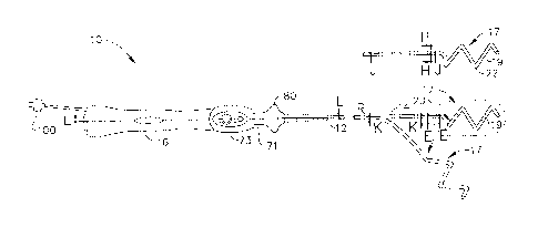
section 14, is accomplished by suitable manipulation of the control handle 16.
Suitable control
handles for manipulating more than one wire are described, for example, in
U.S. Patent Nos.
6,468,260, 6,500,167, and 6,522,933, the disclosures of which are incorporated
herein by
reference. Suitable control handles for manipulating lasso-type catheters are
described in U.S.
Application No. 12/550,307, filed August 28, 2009, and U.S. Application No.
12/550,204, filed
August 28, 2009, the entire disclosures of which are incorporated herein by
reference.
[0094] Alternatively, a catheter having the distal assembly of the
present invention could be
made in accordance with FIG. 22 discussed later where there is no deflection
or helical
-23-
CA 02815653 2013-05-13
1
contraction/expansion mechanisms. The helical design with shape memory element
provides the
force necessary for contact of the catheter to the artery wall, eliminating
the need for component
manipulation (deflection and contraction/expansion). For the catheters that do
not need any
deflection or contraction/expansion means, a simple handle with a connector
and an irrigation
port is all that is necessary. This embodiment is shown and described with
respect to FIG. 24 A
et seq.
[0095] In one embodiment, the catheter includes a control handle 16 as
shown in FIGS. 15
and 16. The control handle 16 includes a deflection control assembly that has
a handle body 74
in which a core 76 is fixedly mounted and a piston 78 is slidably mounted over
a distal region of
the core 76. The piston 78 has a distal portion that extends outside the
handle body. A thumb
knob 80 is mounted on the distal portion so that the user can more easily move
the piston
longitudinally relative to the core 76 and handle body 74. The proximal end of
the catheter body
12 is fixedly mounted to the distal end of the piston 78. An axial passage 79
is provided at the
distal end of the piston, so that various components, including lead wires 40,
41, contraction wire
44, deflection wire 54, sensor cable 46 and irrigation tubing 43 that extend
through the catheter
body 12 can pass into and if appropriate, through the control handle. For
example, the lead wires
40, 41 can extend out the proximal end of the control handle 16 or can be
connected to a
connector that is incorporated into the control handle, as is generally known
in the art.
[00961 The proximal end of the deflection wire 54 enters the control
handle 16, and is
wrapped around a pulley 82 and anchored to the core 76. Longitudinal movement
of the thumb
knob 80 and piston 78 distally relative to the handle body 74 and core 76
draws the proximal end
of the deflection wire 54 distally. As a result, the deflection wire 54 pulls
on the side of the
intermediate section 14 to which it is anchored, thereby deflecting the
intermediate section in
that direction. To straighten the intermediate section 14, the thumb knob 80
is moved proximally
-24-
CA 02815653 2013-05-13
1
which results in the piston 78 being moved proximally back to its original
position relative to the
handle body 74 and core 76.
[00971 The control handle 16 is also used for longitudinal movement of the
contraction wire
44 by means of a rotational control assembly. In the illustrated embodiment,
the rotational
control assembly includes a cam handle 71 and a cam receiver 72. By rotating
the cam handle in
one direction, the cam receiver is drawn proximally to draw on the contraction
wire 44. By
rotating the cam handle in the other direction, the cam receiver is advanced
distally to release the
contraction wire. For example, where the helical form 22 has an original outer
diameter of about
35mm, tightening of the helical form by means of the contraction wire can
reduce the outer
diameter to about 20mm. The contraction wire 44 extends from the catheter body
12 into the
control handle 16, through the axial passage in the piston 82 and through the
core 76 to be
anchored in an adjuster 75 by which tension on the contraction wire can be
adjusted.
[0098] In one embodiment, the position sensor 48 includes a plurality of
single axis sensors
("SAS") carried on the cable 46 that extends through the first lumen 57 of the
distal assembly 17
(FIG. 9), where each SAS occupies a known or predetermined position on the
helical form 22.
The cable 46 extends proximally from the distal assembly 17 through the
central lumen of the
transitional section 20, the fourth lumen 36 of the intermediate section 14
(FIG. 6), the central
lumen 18 of the catheter body 12, and into the control handle 16. Each SA
sensor can be
positioned with a known and equal spacing separating adjacent SA sensors. In
the disclosed
embodiment, the cable carries three SASs that are positioned under the distal-
most AR electrode,
the proximal-most AR electrode, and a mid AR electrode, for sensing location
and/or position of
the helical form. Where the distal assembly carries ten AR electrodes, the
SASs are under
electrodes AR. The SASs enable the helical form to be viewed under mapping
systems
manufactured and sold by Biosense Webster, Inc., including the CARTO, CARTO XP
and
-25-
CA 02815653 2013-05-13
1
NOGA mapping systems. Suitable SASs are described in U.S. Application No.
12/982,765, filed
December 30, 2010, the entire disclosure of which is incorporated herein by
reference.
[0099] In another alternative embodiment of the present invention, as
illustrated in FIG. 2,
the catheter has a distal assembly 17 whose helical form 22 can be varied by
means of a stiffener
or mandrel 84 that is extended through the shape memory support member 50 of
the distal
assembly. As illustrated in FIGS. 17A-17C, the shape memory support member 50
is tubular
(but not necessarily with a circular cross-section) or otherwise hollow so as
to be able to receive
the mandrel whose shape and stiffness/flexibility differ from those of the
support member 50. In
one embodiment as shown in FIG. 17A, the hollow support member 50A includes
multiple shape
memory wires 90 that are coiled together forming a helical hollow strand
tubing. Alternatively,
a hollow support member 50B is formed from a tube with a spiral cut 92 (e.g.,
by laser) along the
length of the member to provide greater flexibility. The cut is made at an
angle 13 between about
30-80 degrees, and preferably about 65 degrees, from the axial direction. As
shown in FIG. 17B,
the spiral cut can be made with a smooth and linear edge 94. In one detailed
embodiment, the
outer diameter of the member 50B is about 0.25mm and the inner diameter is
about 0.20mm.
The width of a strip WS between adjacent cuts is approx. 0.024mm and the width
of the cut WC
is approx. 0.002mm. Alternatively, as shown in FIG. 17C, the spiral cut can
have an interlocking
pattern 96, e.g., a dovetail pattern, so that the member can provide greater
flexibility without
elongation in the axial direction. In one detailed embodiment, the width of a
strip WS between
adjacent cuts is a bout 0.023mm. The widest portion of each dovetail WD is
about 0.005mm and
the depth of the dovetail DD is about 0.006mm and the width of the cut WC is
about 0.001mm.
[00100] As illustrated in FIG. 3, the generally helical form 22 yields to
assume the more
expanded preformed shape of the mandrel 84 received therein and unwinds to a
form with
significantly less curvature (shown in solid lines). Upon removal of the
mandrel 84 from the
-26-
CA 02815653 2013-05-13
1
distal assembly 17, the helical form 22 reassumes the predetermined shape of
the shape memory
support member 50 (shown in broken lines).
[00101] It is understood that in these embodiments, the hollow support member
50 can extend
proximally to at least a proximal portion of the catheter body 12 that remains
outside of the
patient, if not through control handle 16 so the proximal end is accessible to
the operator for
inserting the mandrel. The proximal end can exit the catheter body at a
location near the control
handle or it can extend through the control and exit the proximal end of the
control handle to be
accessed by the operator.
[00102] Thus, the operator can expand or even significantly straighten the
form of the distal
assembly by advancing the mandrel 84 through the hollow support member 50A,
50B, 50C
where the mandrel is straighter and stiffer than the hollow shape-memory
member. In that
regard, it is understood that by providing a mandrel that is stiffer than the
shape-memory
member of the form of the distal assembly, the form can generally assume the
configuration or
shape of the mandrel over the configuration of the shape-memory member.
[00103] The present catheter 10 is a steerable, multi-electrode,
irrigated luminal catheter. The
catheter is deployed in a target region of the body, e.g., the atria of the
heart or the renal artery or
other anatomical structure, through a guiding sheath. The catheter is designed
to facilitate
eleetrophysiologieal mapping of the target region, e.g., the atria, and to
transmit energy, e.g.,
radiofrcquency (RF) current, to the catheter electrodes for ablation purposes,
for example, to
denervate heart tissue or the renal nerves. For ablation, the catheter is used
in conjunction with a
multi-channel RF generator and irrigation pump.
[00104] The configuration of the catheter permits the catheter to make
consistent
circumferential contact with the tissue inside the vessel. Intracardiac
signals are recorded by an
EP Recording System and the location of the catheter is visualized by
fluoroscopy. Once the
-27-
CA 02815653 2013-05-13
1
catheter is in the desired location, energy is delivered (to multiple
electrodes simultaneously or
selectively) to the vessel in unipolar or bipolar mode resulting in
denervation of the vessel.
[00105] In one embodiment, ablation is delivered at a set wattage on the multi-
channel RF
generator. During ablation the multi-channel RF generator monitors the
temperature of the ring
electrode(s) involved and reduces the wattage if the temperature exceeds a
value set by the user.
The multi-channel RF generator routes the RF current through the selected ring
electrodes and
catheter temperature information is sent from the thermocouple on the catheter
to the generator.
[00106] During ablation, an irrigation pump is used to deliver normal
heparinized saline to the
ring electrodes to cool the ring electrodes to prevent blood from coagulating.
The apertures in
the ring electrodes facilitate irrigation of the ablation areas of the
catheter. Where deeper lesions
are desired, the greater flow distribution (without greater flow rate) of each
ring electrode via the
apertures reduces the increased risk of charring and coagulum on the ablation
surfaces that would
normally be encountered when the amount of power delivered to the
electrode/tissue interface is
increased. A greater flow distribution from each ring electrode which leads to
improved
irrigation efficiency offers advantages, including (1) higher power delivery
without increasing
fluid pump flow rate, (2) ability to use currently available, flow rate-
limited pumps, (3) eliminate
need to use multiple pumps, and/or (4) reduction in fluid load on patient
during ablation
procedure.
[00107] FIG. 18 is a schematic pictorial illustration of a system S for
ablation of tissue in a
heart 126 or renal anatomy 129 of a patient 128, in accordance with an
embodiment of the
present invention. Referring to FIGS. 19 -21, an operator 122, such as a
cardiologist,
electrophysiologist or interventional radiologist, inserts a catheter 10 made
in accordance with
the present invention and described in through the vascular system of the
patient (usually starting
at a puncture in the femoral artery) so that the distal end of the catheter
enters a chamber of the
patient's heart or the abdominal aorta (AA) near one of the renal arteries
(RA) which provides
-28-
CA 02815653 2013-05-13
1
blood flow to kidney (K). Operator advances the catheter so that the distal
assembly 117 of the
catheter engages endocardial tissue at a desired location or locations, as
shown in FIG. 21.
Catheter 10 is connected by a suitable connector at its proximal end to a
console 137. The
console comprises an RF generator for applying RF energy through electrodes on
the end section
of the catheter in order to ablate the tissue contacted by the distal section.
Alternatively or
additionally, catheter may be used for other diagnostic and/or therapeutic
functions, such as
intracardiac electrical mapping or other types of ablation therapy.
[00108] In the pictured embodiment, system S uses magnetic positioning sensing
to determine
position coordinates of the distal assembly of the catheter inside heart. To
determine the position
coordinates, a driver circuit 134 in console 137 drives field generators 139
to generate magnetic
fields within the body of patient. Typically, field generators comprise coils,
which are placed
below the patient's torso at known positions external to the body. These coils
generate magnetic
fields in a predetermined working volume that contains heart. One or more
magnetic field
sensors within the end section of catheter generate electrical signals in
response to these
magnetic fields. The console 137 processes these signals in order to determine
the position
(location and/or orientation) coordinates of the distal assembly 117 of the
catheter, and possibly
also the deformation of the distal assembly, as explained below. Console may
use the
coordinates in driving a display 138 to show the location and status of the
catheter. This method
of position sensing and processing is described in detail, for example, in PCT
International
Publication WO 96/05768, whose entire disclosure is incorporated herein by
reference, and is
implemented in the CARTO system produced by Biosense Webster Inc. (Diamond
Bar,
California).
[00109] Alternatively or additionally, system may comprise an automated
mechanism (not
shown) for maneuvering and operating catheter within the body of patient. Such
mechanisms are
typically capable of controlling both the longitudinal motion
(advance/retract) and the rotation of
-29-
CA 02815653 2013-05-13
1
catheter. In such embodiments, console generates a control input for
controlling the motion of
the catheter based on the signals provided by the position sensing system.
[00110] Although FIG. 18 shows a particular system configuration, other system
configurations may be used in alternative embodiments of the present
invention. For example,
the methods described hereinbelow may be applied using position transducers of
other types,
such as impedance-based or ultrasonic position sensors. The term "position
transducer" as used
herein refers to an element mounted on or in catheter that causes console to
receive signals
indicative of the coordinates of the element. The position transducer may thus
comprise a
received in the catheter, which generates a position signal to the control
unit based on energy
received by the transducer; or it may comprise a transmitter, emitting energy
that is sensed by a
receiver external to the probe. Furthermore, the methods described hereinbelow
may similarly
be applied in mapping and measurement applications using not only catheters,
but also probes of
other types, both in the heart and in other body organs and regions.
100111] FIG. 19 is a schematic sectional view of heart 126, showing insertion
of catheter 10
having helical form 22 into the heart, in accordance with an embodiment of the
present
invention. To insert the catheter in the pictured embodiment, the operator
first passes a sheath
140 percutaneously through the vascular system and into right atrium 144 of
the heart through
ascending vena cava 142. The sheath penetrates through interatrial septum 148,
typically via the
fossa ovalis, into left atrium 146. Alternatively, other approach paths may be
used. Catheter is
then inserted through the sheath until a distal assembly 117 of the catheter
passes out of the distal
opening of the end of the sheath 140 into the left atrium 146.
[001121 Operator aligns the longitudinal axis of sheath 140 (and of catheter)
inside left atrium
146 with the axis of one of pulmonary veins. He may use the thumb knob 80 of
the control
handle 16 to deflect the intermediate section 14 in directing the distal
assembly 117 toward the
target vessel. The operator may carry out this alignment using the position
sensing methods
-30-
CA 02815653 2013-05-13
1
described above, along with a pre-acquired map or image of heart.
Alternatively or additionally,
the alignment may be performed under fluoroscopic or other means of
visualization. The
operator advances the catheter toward the target pulmonary vein so that the
distal assembly 117
contacts the wall of the pulmonary vein. By manipulating the cam handle 71,
the helical form of
the distal assembly 117 is expanded or contracted to fit inside the PV and
contact the wall. In the
disclosed embodiment, the contraction wire 44 is drawn proximally by the cam
receiver 72 to
tighten and decrease the diameter of the helical form when the cam handle is
turned in one
direction. By turning the cam handle in the opposition direction, the cam
receiver releases the
contraction wire to allow the helical form to expand and return to its
original diameter.
[001131 The operator can then rotate the catheter about its axis within the
sheath so that the
distal assembly traces an annular path around the inner circumference of the
vein. Meanwhile,
the operator actuates RF generator to ablate the tissue in contact with the AR
electrodes along the
path. Simultaneously or in between RF pluses, impedance and/or PV potential
recordings can be
made with the electrodes. After completing this procedure around one pulmonary
vein, the
operator may shift the sheath and catheter and repeat the procedure around one
or more of the
other pulmonary veins.
[001141 A similar procedure is used in FIGS. 20 and 21 to ablate tissue inside
the renal artery
(RA) in order to denervate the renal nerves that are present in the artery.
Operator aligns the
longitudinal axis of sheath 140 (and of catheter) inside abdominal aorta AA
with the axis of one
of renal arteries (RA). He may use the thumb knob 80 of the control handle 16
to deflect the
intermediate section 14 in directing the distal assembly 117 toward the target
artery. The
operator may carry out this alignment using the position sensing methods
described above, along
with a pre-acquired map or image of the renal anatomy. Alternatively or
additionally, the
alignment may be performed under fluoroscopic or other means of visualization.
The operator
advances the catheter toward the target renal artery vein so that the distal
assembly 117 enters the
-31-
CA 02815653 2013-05-13
1
artery. By manipulating the cam handle 71, the helical form of the distal
assembly 117 is
contracted or expanded to fit inside the renal artery RA) and to cause ring
electrodes 19 to touch
the wall of the renal artery. In the disclosed embodiment, the contraction
wire 44 is drawn
proximally by the cam receiver 72 to tighten and decrease the diameter of the
helical form when
the cam handle is turned in one direction. By turning the cam handle in the
opposition direction,
the cam receiver releases the contraction wire to allow the helical form to
expand and return to
its original diameter.
[00115] The operator can then rotate the catheter about its axis within the
sheath so that the
distal assembly traces an annular path around the inner circumference of the
artery. Meanwhile,
the operator actuates RF generator to ablate the tissue in contact with the AR
electrodes along the
path. Simultaneously or in between RF pluses, impedance and/or PV potential
recordings can be
made with the electrodes. After completing this procedure around one pulmonary
vein, the
operator may shift the sheath and catheter and repeat the procedure inside the
other renal artery.
[00116] FIG. 22 is a perspective view of another embodiment of a distal
assembly of a
catheter in accordance with the present invention. Distal assembly 117
comprises a plurality of
electrodes 19 having a plurality of apertures 69 as described above), and a
multi-lumen tube 125
having an irrigation lumen 130 and a lead wire lumen 131 for the
thermocouple/rf wires which
thermocouples 135 are mounted at or near the outermost diameter of the
electrodes and at the
outermost diameter of the helical shape for tissue contact. An additional
lumen 132 houses the
nitinol wire 121 provides the shape to the helix when it is unconstrained by a
sheath, mandrel or
guidewire. The dome 136 is provides an atraumatic tip and also an anchor for
the nitinol helix
121. The nitinol helix extends into the tip of the distal assembly distal the
distal most electrode
19 which tip provides a leader for positioning the catheter into the PV, renal
artery, renal vein or
other vessel.
-32-
CA 02815653 2013-05-13
1
[00117] FIG. 23 is a cross-section of the distal assembly of FIG. 22 through M-
M showing
multi-lumen tube 125 with irrigation lumen 130, nitinol helix lumen 132 and
lead wire lumen
131.
[00118] FIG. 24A is a side view of an alternative embodiment of a catheter in
accordance with
the present invention. FIG. 24B is a cross-sectional view of the proximal
portion of FIG. 24A
through line N-N. Control handle 116 is a generally cylindrical tubular
structure but can also take
other shapes and configurations that provide the user of the device with the
ability to manipulate
the catheter while providing an interior cavity for passage of components.
Control handle 116 is
made of an injection molded polymer such as polyethylene, polycarbonate or ABS
or other
similar material. Connector 118 is inserted into the proximal end of control
handle 116 and
provides an electrical connection to a mating connector and cable assembly
that is connected to
an RF generator. Connector 118 is secured through the use of epoxy or other
similar means.
Lead wire assembly 143 comprises a Teflon sheath and five pairs of lead wires
41, 42 housed
therein, one pair for each thermocouple 135 and ring electrode 19. The
proximal end of each
lead wire is electrically and mechanically connected to the connector 118
through the use of
solder or other means. Irrigation luer hub 110 is a fitting capable of being
attached to mating
connector from an irrigation source such as an irrigation pump (not shown).
Irrigation luer hub
110 is attached to irrigation side arm 111 using polyamide to form a seal
against fluid intrusion.
Irrigation fluid is then conveyed from the irrigation hub through the
irrigation lumen 130a.
Irrigation lumen 130a passes through the lumen in side arm 111 through the
wall of the control
handle 116 through the shaft 145 into the multi-lumen tube 125 for
approximately 3 mm into the
irrigation lumen 130 in multi-lumen tube 125 distal assembly 117 in order to
convey irrigation
fluid to each ring electrode 19 which has a plurality of holes therethrough.
[00119] Control handle 116 has a portion which of a smaller diameter 116a
which is adapted
to receive the proximal end of the catheter assembly 150 which is comprised of
strain relief
-33-
CA 02815653 2013-05-13
1
element 151, 152 and shaft 145 through which lead wire assembly 143 and
irrigation lumen 130a
pass. Strain relief elements 151 and 152 in the preferred embodiment are two
shrink sleeves
made of polyolefin or similar material which are heated to shrink over the
shaft 145.
Polyurethane is then used to attach the strain relief elements 151 and 152
into the handle portion
116a.
[00120] The working length (L) of the catheter assembly 150 is approximately
90 cm from the
distal end of strain relief element 152 to the distal tip of the distal
assembly 117 when used for
renal ablation. The working length may vary depending on the application.
Distal assembly 117
comprises a multi-lumen tube 125 which has a plurality of ring electrodes 19
mounted thereon.
In a preferred embodiment for renal ablation five ring electrodes are used
each having an
electrode length (W) of 3 millimeters and an inter-electrode spacing (S) of 4
millimeters. The
maximum diameter of the helix is approximately 10 mm when un-constricted. The
ring
electrodes 19 preferably have a maximum outer diameter of 2 mm at the middle
and a minimum
outer diameter of 1.7 mm at the narrower ends. The ring electrodes may be made
on any material
described herein but are preferably made of 90% platinum and 10% iridium but
cold be
comprised a combination of these and/or other suitable noble metals such as
gold and palladium.
Multi-lumen tube 125 is made of a material that is more flexible than the
material in the shaft
145 preferably multi-lumen tube 125 is made of 35D PEBAX with no wire braid
although other
materials and durometers may be used depending on the desired stiffness of the
distal assembly.
Shaft 145 is made of pellethane, polyurethane or PEBAX and contains an
internal stiffener as
described herein which is an inner tube made of nylon or polyimide or similar
material.
[00121] FIGS. 25A and 25B show a portion of the distal assembly 117 containing
the ring
electrodes 19 each having a preferable length (W) of approximately 3 mm and an
inter-electrode
spacing (S) of approximately 4 millimeters. Each pair of lead wires 41 and 42
are welded to a
respective ring electrode to provide a robust connection (further depicted in
FIG. 27).
-34-
CA 02815653 2013-05-13
1
Polyurethane coating 123 is placed over each end of each ring electrode in
order to seal against a
fluid intrusion and to provide an atraumatic transition between the electrodes
19 and the multi-
lumen tube 125 of distal assembly 117. In FIG. 25 the polyurethane coating 123
is not depicted
and multi-lumen tube 125 is shown transparent so as to show the placement of
the lead assembly
143 which at this point comprises the five pairs of lead wires (41, 42) and a
polyamide coating
over the bundle of wires. In FIG. 27 the welded connection of a pair of lead
wires (41, 42) to a
specific ring electrode 19 is shown. Also, the cross-sectional area of the gap
between the wall
portion of the ring electrode 19 having the greater outer diameter and the
multi-lumen tube 125
can be seen. This gap is the space through which irrigation fluid flows from
the irrigation lumen
130 through breach hole 133 to the holes in the wall of ring electrode 19. The
breach hole 133
should be positioned at about the half-way (W/2) point along the length of the
ring electrode 19.
[00122] FIGS. 26A-D show the distal assembly 117 connected to shaft 145 and
various cross-
sections therethrough. FIG. 26B is a cross-sectional view of FIG. 26A through
o0-0. FIG. 26C
is a cross-sectional view of FIG. 26A though lineP-P. FIG. 26D is a cross-
sectional view
through line Q-Q in shaft 145 in FIG. 24A. Atraumatic tip dome 136 is a
polyurethane dome
with a shaft that extends into the end of the irrigation lumen 130 at the end
of the multi-lumen
tube 125. The nitinol wire/shape memory support member 121 extends from at or
near the distal
end of the multi-lumen tube 125 into the shaft 145 for approximately 25
millimeters into the
shaft. This provides stability to the distal assembly 117. Nitinol wire 121 is
preferably square in
cross-section .009 inch by .009 inch) but could be square, circular or
rectangular in cross-section
with a width or diameter between .006 inch and .012 inch. The nitinol wire is
pre-formed to
take a helical shape having a diameter of approximately 10 mm and a helical
shape length of
approximately 20 mm electrode edge to edge when it is in not constrained
within a sheath and a
straight length of approximately 36 mm proximal edge of most proximal ring
electrode 19 to the
distal tip when constrained in a sheath. The nitinol wire will impart this
helical shape on the
-35-
CA 02815653 2013-05-13
1
other components of distal assembly 117. In FIGS. 26B and 26C the cross-
sections of multi-
lumen tube 125 shows ring electrode 19 mounted on multi-lumen tube 125. Multi-
lumen tube
125 also contains an irrigation lumen 130 and a lead wire lumen 131 housing
the lead wire
assembly 143 having a pair of lead wires 41, 42 for each electrode. In FIG.
26B the connection
of a first pair of lead wires (41, 42) to electrode 19 is shown. The
additional pairs of lead wires
can be seen in the remainder of lead wire assembly 143 in FIG. 26B. FIG. 26C
shows the final
pair of lead wires (41, 42) attached to the distal most electrode 19. Lumen
131 houses the nitinol
wire 121. Lumen 153 is in multi-lumen tube 125 is unused in the preferred
embodiment but
could be used for wiring for additional thermocouples or other sensors that
are desired in the tip
assembly. In FIG. 26D the arrangement of the nitinol wire 121, irrigation
lumen 130 and the
lead wire assembly 143 within the shaft 145 can be seen. Stiffener 147
provides added stiffness
to the shaft 145 and is comprised of a material such as polyimide or nylon,
preferably polyimide
having a thickness of approximately .002 thousandths. The stiffener 147 runs
substantially the
entire length of the shaft 145. In FIG. 26A the polyurethane bond 159 of the
shaft 145 and the
multi-lumen tube 125 is depicted. This preferred polyurethane bond 159
prevents fluids from
entering at the junction of these two elements. Other methods of bonding such
as heat sealing or
other glues may be used.
[00123] In use, the catheter assembly 150 depicted in FIGS. 24A-B, FIGS. 25A-
B, FIGS.
26A-D and FIG. 27 is used with a sheath, preferably, a steerable sheath (not
shown) which
facilitates the placement of the catheter in the proper place in the anatomy
for the desired
ablation/denervation. Once the catheter assembly 150 exits the sheath the
nitinol wire/support
member121 will cause the distal assembly to take the pre-configured helical
shape. The 10 mm
diameter helical shape will provide sufficient apposition of the ring
electrodes against the interior
wall of the renal artery to provide contact for an ablation that upon the
delivery of RF energy
-36-
CA 02815653 2013-05-13
1
from a generator to one or more of the ring electrodes will result in the
denervation or partial
denervation of the artery.
[00124] The preceding description has been presented with reference to
presently preferred
embodiments of the invention. Workers skilled in the art and technology to
which this invention
pertains will appreciate that alterations and changes in the described
structure may be practiced
without meaningfully departing from the principal, spirit and scope of this
invention. Any
feature or structure disclosed in one embodiment may be incorporated in lieu
of or in addition to
other features of any other embodiments, as needed or appropriate. As
understood by one of
ordinary skill in the art, the drawings are not necessarily to scale.
Accordingly, the foregoing
description should not be read as pertaining only to the precise structures
described and
illustrated in the accompanying drawings, but rather should be read consistent
with and as
support to the following claims which are to have their fullest and fair
scope.
20
-37-