Note : Les descriptions sont présentées dans la langue officielle dans laquelle elles ont été soumises.
CA 02816414 2013-05-28
=
65666-254
LUGGAGE WITH A RECESSED ZIPPER
[0001]
TECHNOLOGICAL FIELD
[0002] The technological field generally relates to luggage.
BACKGROUND
[0003] Zippers are often provided on luggage to access luggage
compartments. Each zipper typically includes a zipper track, a zipper slider,
and a
zip pull tab. For zippers positioned on the exterior of the luggage, the
zipper track is
typically positioned approximately flush with an outer surface of the luggage.
Such a
configuration makes the zipper track susceptible to being damaged from contact
with
other objects. Further, in such a configuration, the zipper slider usually
projects
outwardly from the outer surface of the luggage. This outward projection also
makes
the zipper slider vulnerable to being damaged.
SUMMARY
[0004] One embodiment of a luggage piece may include at least six sides
defining an enclosed space and a zipper positioned along at least one side of
the at
least six sides. The zipper and the at least one side may be configured so
that the
zipper provides access to the enclosed space. The zipper may include a zipper
track. A first segment of the zipper track may be recessed relative to an
outermost
surface of the at least one side. A second segment of the zipper track may be
positioned at approximately the outermost surface of the at least one side.
[0005] Another embodiment of a luggage piece may include a front side,
a rear
side, a right side, a left side, a top side, and a bottom side. The front,
rear, right, left,
top, and bottom sides may define an enclosed space. A zipper may be positioned
along at least portions of the right, left, top, and bottom sides. The zipper
and the
right, left, top, and bottom sides may be
1
CA 02816414 2013-04-29
WO 2012/056009
PCT/EP2011/069011
configured so that the zipper provides access to the enclosed space. The
zipper may include a
zipper track. A first segment of the zipper track may be recessed relative to
an outermost
surface of the top side, and a second segment of the zipper track may be
positioned at
approximately the outermost surface of the top side.
[0006] Yet another embodiment of a luggage piece may include a base, a lid and
a zipper. The
lid may be pivotally joined to the base to pivot between at least a first
position where the base
and the lid define a substantially enclosed space and a second position to
allow access to the
substantially enclosed space. The lid and the base together may define an area
recessed
relative to outermost surfaces of the lid and the base when the lid and the
base are configured
in the first position. The zipper may maintain the lid and the base in the
first position. The
zipper may be joined to the lid and the base at least within the recessed
area.
[00071 Another embodiment of a luggage piece may include a base, a lid, and a
zipper. The lid
may be pivotally joined to the base to pivot between at least a first position
where the base and
the lid define a substantially enclosed space and a second position to allow
access to the
substantially enclosed space. The zipper may be configured in a first
configuration to secure
the lid and the base in the first position and in a second configuration to
allow the lid and the
base to be selectively moved between the first and second positions. The base
may include a
first shell that defines at least a first outer portion of the base. The lid
may include a second
shell that defines at least a first outer portion of the lid. A first segment
of the zipper may be
joined to the first and second shells on inner facing surfaces of the first
and second shells. The
thicknesses of the first and second shells may be sufficiently large so that
at least along the first
segment of the zipper, a portion of the zipper is recessed relative to the
outermost portions of
the first and second shells that are proximate the zipper.
[0008] Still another embodiment of the luggage piece may include a base, a
lid, and a zipper.
The lid may be pivotally joined to the base to pivot between at least a first
position where the
base and the lid define a substantially enclosed space and a second position
to allow access to
the substantially enclosed space. The zipper may be configured in a first
configuration to
secure the lid and the base in the first position and in a second
configuration to allow the lid and
the base to be selectively moved between the first and second positions. The
base may include
a first outer member that defines at least an outer portion of the base. The
lid may include a
second outer member that defines at least an outer portion of the lid. A first
support member
2
CA 02816414 2013-05-28
65666-254
may be joined to an inner facing surface of the first outer member. The first
support
member may be located between the first outer member and a segment of the
zipper.
A second support member may be joined to an inner facing surface of the second
outer member. The second support member may be located between the second
outer member and the segment of the zipper. A combined thickness of the first
support member and the first outer member and a combined thickness of the
second
support member and the second outer member may both be sufficiently large so
that
along the segment of the zipper, a portion of the zipper is recessed relative
to the
outermost portions of the first and second outer members that are proximate to
the
zipper.
[0009] Another embodiment of a luggage piece may include a base, a
lid, a
zipper, and a carry handle. The lid may be pivotally joined to the base to
pivot
between at least a first position where the base and the lid define a
substantially
enclosed space and a second position to allow access to the substantially
enclosed
space. The zipper may be configurable in a first configuration to secure the
lid and
the base in the first position and in a second configuration to allow the lid
and the
base to be selectively moved between the first and second positions. The carry
handle may be joined to the lid and the base.
[0010] Yet another embodiment of a luggage piece may include a base, a
lid,
and a carry handle. The lid may be pivotally joined to the base by a hinge to
pivot
between at least a first position where the base and the lid define a
substantially
enclosed space and a second position to allow access to the substantially
enclosed
space. The carry handle may be joined to the lid, the base, and the hinge.
[0011] A further embodiment of a luggage piece may include a base, a
lid, and
a carry handle. The lid may be pivotally joined to the base to pivot between
at least a
first position where the base and the lid define a substantially enclosed
space and a
second position to allow access to the substantially enclosed space. The carry
handle may be joined to the lid and the base, and the carry handle may be
positioned
proximate abutting edges of the lid and the base.
3
81770911
[0011a] In accordance with another embodiment of the invention, there is
provided a
luggage case, comprising: a base; a lid pivotally joined to the base along
abutting
edges of the lid and the base; a hinge member pivotally joining the lid and
base; the
base and the lid defining respective halves of the luggage case that together
define
opposing front and rear sides, opposing top and bottom sides, and opposing
left and
right sides of the luggage case, the abutting edges are defined along the left
side,
right side, top side and bottom side of the luggage case, and the hinge member
joining one side of the lid to the base along the abutting edges; one or more
wheels
joined to the bottom side of the luggage case; a carry handle joined to at
least one of
the base and the lid at a side adjacent to the bottom side of the luggage
case; and
the hinge member overlying the abutting edges, the carry handle overlying the
hinge
member and the abutting edges, and the carry handle and the hinge member
overlie
the abutting edges, wherein the carry handle is located above the hinge member
on a
same side of the luggage case.
[0011b] In accordance with another embodiment of the invention, there is
provided a
luggage case comprising: a base including abutting edges; a lid including
abutting
edges; a hinge member pivotally joining the lid and the base, the hinge member
positioned over the abutting edges of the base and the lid; and a handle
joined to at
least one of the base and the lid, the handle positioned over the hinge member
and
the abutting edges of the base and the lid, wherein the handle is located
above the
hinge member on a same side of the luggage case.
BRIEF DESCRIPTION OF THE DRAWINGS
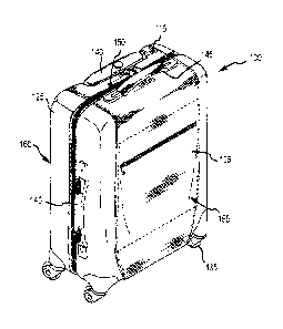
[0012] Fig. 1 shows a perspective view of an embodiment of a luggage piece
that incorporates a recessed zipper.
3a
CA 2816414 2019-02-26
CA 02816414 2013-04-29
WO 2012/056009
PCT/EP2011/069011
[0013] Fig. 2 shows another perspective view of the luggage piece shown in
Fig. '1
[0014] Fig. 3 shows a front elevation view of the luggage piece shown in Fig
1.
[0015] Fig. 4 shows a side elevation view of the luggage piece shown in Fig. 1
[0016] Fig. 5 shows a rear elevation view of the luggage piece shown in Fig.
1.
[0017] Fig. 6 shows a cross-section view of the luggage piece shown in Fig 1,
viewed along line
6-6 in Fig. 4.
[0018] Fig. 7 shows a cross-section view of the luggage piece shown in Fig 1,
viewed along line
7-7 in Fig. 5.
[0019] Fig. 8 shows a partial cross-section view of the luggage piece shown in
Fig. 1, viewed
along line 8-8 in Fig. 3.
[0020] Fig. 9 shows a partial cross-section view of the luggage piece shown in
Fig. 1, viewed
along line 9-9 in Fig. 3.
[0021] Fig. 10 shows a partial cross-section view of the luggage piece shown
in Fig. 1, viewed
along line 10-10 in Fig. 3.
[0022] Fig. 11 shows an exploded view of some of the components that form the
luggage piece
shown in Fig. 1.
[0023] Fig. 12 shows a partial cross-section view of the luggage piece shown
in Fig. 1 that is
similar to the view shown in Fig. 7 except this view shows another way to join
various
components of the luggage piece together.
[0024] Fig. 13 shows a partial cross-section view of the luggage piece shown
in Fig. 1 that is
similar to the view shown in Fig. 8 except this view shows another way to join
various
components of the luggage piece together.
[0025] Fig. 14 shows a partial cross-section view of the luggage piece shown
in Fig. 1 that is
similar to the view shown in Fig. 9 except this view shows another way to join
various
components of the luggage piece together.
4
CA 02816414 2013-04-29
WO 2012/056009
PCT/EP2011/069011
[0026] Fig. 15 shows a partial cross-section view of the luggage piece shown
in Fig. 1 that is
similar to the view shown in Fig. 10 except this view shows another way to
join various
components of the luggage piece together.
[0027] Figs. 16A-D show schematic views of one method to form the corner
supports for the
luggage piece shown in Fig. 1.
[0028] Fig. 17 shows a perspective view of a second embodiment of a luggage
piece that
incorporates a recessed zipper.
[0029] Fig. 18 shows a bottom view of the luggage piece shown in Fig. 17.
[0030] Fig. 19 shows a side view of the luggage piece shown in Fig. 17.
[0031] Fig. 20 shows another perspective view of the of the luggage piece
shown in Fig. 17.
[0032] Fig. 21 shows another side view of the luggage piece shown in Fig_ 17.
[0033] Fig. 22 shows atop view of the luggage piece shown in Fig. 17.
[0034] Fig. 23 shows a cross-section view of the luggage piece shown in Fig.
17, viewed along
line 23-23 in Fig. 19.
[0035] Fig. 24 shows a partial cross-section view of the luggage piece shown
in Fig. 17, viewed
along line 24-24 in Fig. 23.
[0036] Fig. 25 shows a partial cross-section view of the luggage piece shown
in Fig. 17, viewed
along line 25-25 in Fig. 23.
[0037] Fig. 26 shows a front perspective view of third embodiment of a luggage
piece that
incorporates a recessed zipper.
[0038] Fig. 27 shows a front elevation view of the luggage piece of Fig. 26.
[0039] Fig. 28 shows a side elevation view of the luggage piece of Fig. 26.
[0040] Fig. 29 shows a cross-section view of the luggage piece of Fig. 26,
viewed along line 29-
29 in Fig. 27.
CA 02816414 2013-04-29
WO 2012/056009
PCT/EP2011/069011
[00411 Fig. 30 shows a cross-section view of the luggage piece of Fig. 26,
viewed along line 30-
30 in Fig. 27.
[0042] Fig. 31 shows a cross-section view of the luggage piece of Fig. 26,
viewed along line 31-
31 in Fig. 27.
[0043] Fig. 32 shows a cross-section view of the luggage piece of Fig. 26,
viewed along line 32-
32 in Fig. 27.
[0044] Fig. 33 shows a cross-section view of the luggage piece of Fig. 26,
viewed along line 33-
33 in Fig. 28.
[0045] Fig. 34 shows a schematic partial top view of a fourth embodiment of a
luggage piece
that incorporates a recessed zipper and an expansion zipper, showing the
expansion zipper in a
closed position.
[0046] Fig. 35 shows a schematic partial top view of the luggage piece of Fig.
34, showing the
expansion zipper in an open position.
DETAILED DESCRIPTION
[0047] Described herein are luggage pieces that incorporate at least one
recessed zipper.
Such a luggage piece may include a front side, a rear side, a top side, a
bottom side, a right
side and a left side that define an enclosed space. The enclosed space may be
divided into one
or more compartments. The luggage piece may further include at least one
zipper to access the
enclosed space. The at least one zipper may include a zipper track, at least
one zipper slider,
and at least one zipper tab. At least a portion of the zipper track may be
positioned within one
or more recessed areas defined by at least some of the sides of the luggage or
may be
otherwise configured relative to other components of the luggage piece to be
at least partially
recessed relative to an outer surface of the luggage piece. In some
embodiments, the zipper
track may be recessed relative to an outer surface of the luggage piece along
substantially the
entire length of the zipper track.
[0048] Fig. 1 shows a front perspective view of one example of a luggage piece
100 that utilizes
a recessed zipper, and Fig. 2 shows a rear perspective view of the luggage
piece 100 shown in
Fig. 1. With reference to Figs. 1 and 2, the luggage piece 100 may include a
front side 105, a
6
CA 02816414 2013-04-29
WO 2012/056009
PCT/EP2011/069011
rear side 110, a top side 115, a bottom side 120, a right side 125 and a left
side 130 that define
an enclosed space (not shown). The enclosed space may be divided into one or
more
compartments. The luggage piece 100 may further include one or more wheels 135
joined to
the bottom side 120 of the luggage piece 100. The wheels 135 may be spinner
wheels, as
shown in Fig. 1, or fixed direction wheels. While four spinner wheels 135 are
shown in the
figures, the luggage piece 100 may have more or less than four wheels. In
embodiments that
use two wheels, one or more foots or other supports may be joined to the
bottom side of the
luggage piece to facilitate positioning and maintaining the luggage piece in
an upright position,
similar to the upright position for the luggage piece 100 shown in Figs. '1
and 2.
[0049] The luggage piece 100 may further including one or more handles. At
least one of the
handles may be a telescoping handle 140 that may be selectively positioned
between a
retracted position and one or more extended positions. In an extended
position, the telescoping
handle 140 may be used to facilitate using the wheels 135 to push or pull the
luggage piece 100
along a support surface. One or more of the handles may be carry handles 145.
In Fig. 1, two
carry handles 145 are shown: one joined to top side 115 of the luggage piece
100, and the other
to the right side 125 of the luggage piece 100. The carry handles 145 may be
used to lift or
carrying the luggage piece 100. Of course, more or less than two carry handles
145 could be
joined to the luggage piece 100.
[0050] The luggage piece 100 may further include a first zipper 150 that
provides access to the
enclosed space. More particularly, the front side 105 and portions of the
right, left, top, and
bottom sides 125, 130, 115, 120 of the luggage piece 100 may be joined to
define a first
luggage portion 155, or first shell portion, of the luggage piece 100 that can
move in unison.
Similarly, the rear side 110 and remaining portions of the right, left, top,
and bottom sides 125,
130, 115, 120 of the luggage piece 100 may define a second luggage portion
160, or second
shell portion, of the luggage piece 100 that move in unison. The first luggage
portion 155 may
also be referred to as a lid or base, and the second luggage portion 160 may
be referred to as a
base (when the first luggage portion 155 is considered to be lid) or lid (when
the first luggage
portion 155 is considered to be a base). The first and second luggage portions
155, 160 may
be joined by a hinge 165 that allows them to be selectively pivoted relative
to each other to
different configurations while remaining joined via the hinge 165. In the
configuration shown in
Fig. 1, the first and second luggage portions 155, 160 collectively define the
enclosed spaced.
7
CA 02816414 2013-04-29
WO 2012/056009 PCT/EP2011/069011
When pivoted to other positions where the abutting edges of first and second
luggage portions
155, 160 are separated, the enclosed space may be accessed.
[0051] The first zipper 150 may be positioned along the abutting edges of the
first and second
luggage portions 155, 160. The first zipper 150 may include a zipper track
170, two zipper
sliders 175, and two zipper tabs 180. Each zipper tab 180 may be joined to a
respective zipper
slider 175 to facilitate selectively moving its respective zipper slider 175
along the zipper track
170. The zipper track 170 may be positioned along the abutting edges of the
first and second
luggage portions 155, 160 from at least one end portion of the hinge 165 to
the distal end
portion of the hinge 165. For example, the zipper track 170 may extend from at
least an upper
end portion 185 of the hinge 165 to the top side 115 of the luggage piece 100,
along the top
side 115 of the luggage piece 100 to the right side 125 of the luggage piece
100, along the right
side 125 of the luggage piece 100 to the bottom side 120 of the luggage piece
100, along the
bottom side 120 of the luggage piece 100 to the left side 130 of the luggage
piece 100, and
along the left side 130 of the luggage piece 100 to at least a lower end
portion 190 of the hinge
165.
[0052] With reference to Fig. 8, the zipper track 170 may include a first set
of teeth 195 joined
to a first zipper tape 205 and a second set of teeth 200 joined to a second
zipper tape 210. The
first set of teeth 195 may be joined to the edge 215 of the first luggage
portion 155 that abuts
the second luggage portion 160, and the second set of teeth 200 may be joined
to the edge 220
of the second luggage portion 160 that abuts the first luggage portion 155.
The first and second
sets of teeth 195, 200 may be joined to the first and second luggage portions
155, 160,
respectively, by any suitable connection method, including, but not limited
to, by sewing,
bonding, adhering, welding, and so on.
[0053] The teeth of first set of teeth 195 may be configured to selectively
engage corresponding
teeth on the second set of teeth 200. Selectively moving the zipper sliders
175 along the zipper
track 170 causes the teeth of the first and second sets of teeth 195, 200 to
be selectively
engaged and disengaged. When one or both of the zipper sliders 175 are moved
away from
each other, at least some of the teeth in the first and second sets of teeth
195, 200 are
disengaged, thus creating an opening in the zipper track 170. When a
sufficient number of
teeth in the first and second sets of teeth 195, 200 are disengaged, the
opening is sufficiently
large to allow access to the enclosed space defined by the first and second
luggage portions
8
CA 02816414 2013-04-29
WO 2012/056009
PCT/EP2011/069011
155, 160. When the teeth of the first and second sets of teeth 195, 200 along
substantially the
entire length of the zipper track 170 are disengaged, the first luggage
portion 155 may be
selectively pivoted relative to the second luggage portion 160, or vice versa.
Similarly, when a
substantial majority of the teeth of the first and second sets of teeth 195,
200 are engaged, the
first and second luggage portions 155, 160 cannot be selectively pivoted
relative to each other.
[0054] While two zipper sliders 175 are shown in the various figures to open
and close the
luggage piece 100, the first zipper 150 may only include one zipper slider
175. When the first
zipper 150 includes a single zipper slider 175, moving the zipper slider 175
in one direction
engages the teeth of the first and second sets of teeth 195, 200 and moving
the zipper slider
175 in the opposite direction disengages the teeth. Thus, when the single
zipper slider 175 is
positioned at one end of the zipper track 170, substantially all of the teeth
in the first and second
sets of teeth 195, 200 are disengaged, and when the single zipper slider 175
is positioned at the
other end of the zipper track 170, substantially all of the teeth for the
first and second sets of
teeth 195, 200 are engaged. In other respects, the first zipper 150 with a
single zipper slider
175 operates in a similar manner as a first zipper 150 with two zipper sliders
175. Specifically,
when all teeth of the first and second sets of teeth 195, 200 are engaged,
access to the
enclosed space is prevented. When a sufficient number of teeth of the first
and second sets of
teeth 195, 200 are disengaged, the enclosed space may be accessed. When
substantially all of
the teeth of the first and second sets of teeth 195, 200 are disengaged, the
first and second
luggage portions 155, 160 may be selectively pivoted relative to each other.
[0055] With reference to Figs. 1-3, 6-10, and 12-15, at least a portion of the
zipper track 170
may be recessed relative to the outer surfaces of the first and second luggage
portions 155,
160. In some embodiments, the zipper track 170 may be recessed along one or
more portions
or segments of the zipper track's length. In other embodiments, the zipper
track 170 may be
recessed along the entire length of the zipper track 170.
[0056] Figs. 1-15 show various embodiments of the luggage piece 100 in which
the zipper track
170 is recessed along only portions or segments of the zipper track's length.
With reference to
Figs. 1, 2 and 8, the zipper track 170 may be recessed along the right and
left sides 125, 130 of
the luggage piece 100 by positioning the zipper track 170 within recessed
areas defined by the
right and left sides 125, 130 of the luggage piece 100. With reference to
Figs. 8-10 and 12-15,
as the zipper track 170 transitions from the right side 125 to the top side
115 of the luggage
9
CA 02816414 2013-04-29
WO 2012/056009
PCT/EP2011/069011
piece 100, the recessed area defined by the outer facing surface of the
luggage piece 100
tapers. This tapering continues until at top side 115 of the luggage piece
100, the outer facing
surface of the luggage piece 100 ceases to define a recessed area. Near this
location, the
zipper track 170 may be positioned at or near the outermost surface 225 of the
top side 115 of
the luggage piece 100. The zipper track 170 may be maintained at this position
relative to the
outermost surface 225 of the top side 115 of the luggage piece 100 until the
zipper track 170
nears the left side 130 of the luggage piece 100. As the zipper track 170
approaches the left
side 130 of the luggage piece 100, outer facing surface of the top side 115 of
the luggage piece
100 begins to taper inward to define a recessed area relative to the outermost
surface 225 of
the top side 115. This tapering continues until the full depth of the recessed
area is defined
along the left side 130 of the luggage piece 100. A similar tapering of the
recessed area occurs
proximate the transition from the right and left sides 125, 130 of the luggage
piece 100 to the
bottom side 120 of the luggage piece 100. Further, as with the positioning of
the zipper track
170 on the top side 115 of the luggage piece 100, at least a portion or
segment of the zipper
track 170 on the bottom side 120 of the luggage piece 100 may positioned at or
near the
outermost surface of the bottom side 120 of the luggage piece 100.
[0057] For embodiments where only portions or segments of the zipper track 170
are recessed
relative to the outermost surfaces of the sides 105, 110, 115, 120, 125, 130
of the luggage piece
100, the location of the change from the recessed to the non-recessed
portions, or segments,
may depend, at least in part, on how the luggage piece 100 is constructed. For
example, the
luggage piece 100 shown in Figs. 1-15 depicts a hybrid construction that
includes components
of a relatively rigid, semi-rigid, hard, or semi-hard material (collectively
''harder material") and a
relatively soft or non-rigid material (collectively "softer material").
Specifically, the right and left
sides 125, 130 of the luggage piece 100 along with portions of the front,
rear, top, and bottom
sides 105, 110, 115, 120 of the luggage piece 100 adjacent the right and left
sides 125, 130
may be formed using a harder material, such as acrylonitrile-butadiene-styrene
("ABS") plastic,
polycarbonate plastic, an ABS/polycarbonate plastic blend, and so on. The
harder areas may
define four corner columns or supports for the luggage piece 100. The
remaining or central
portions of the front, rear, top, and bottom sides 105, 110, 115, 120 may be
formed using a
softer material, such as fabric or the like. In these softer regions, one or
more support
members, such as curved polypropylene ("PP") or polyethylene ("PE") sheets,
may be provided
CA 02816414 2013-04-29
WO 2012/056009
PCT/EP2011/069011
at the top and bottom sides 115, 120 of the luggage piece 100 to help to
maintain the shape of
the luggage piece 100 in these regions.
[0058] While the harder areas are shown as vertical columns, these areas could
be formed as
horizontal columns positioned at the top and bottom sides 115, 120 of the
luggage piece 100.
In such a configuration, the harder areas would generally include the top and
bottom sides 115
120 of the luggage piece 100 along with portions of the front rear, right, and
left sides 105, 110,
125, 130 of the luggage piece 100. Like the vertical column embodiment, the
remaining
portions of the front, rear, right, and left sides 105, 110, 125, 130 may be
formed using a
relatively soft or pliable material, with support material also provided, as
needed.
[0059] The harder and softer materials forming the sides 105, 110, 115, 120,
125, 130 of the
luggage piece 100 may be joined by any suitable method, including, but not
limited to, by
stitching, bonding, welding or adhering the materials at their abutting edges.
Proximate, or at
the location, of the transition from the harder region to the softer region,
the recess relative to
the outermost surfaces of the sides 105, 110, 115, 120, 125, 130 may end so
that at, or near,
this transition, the zipper track 170 ceases to be recessed relative to the
outermost surfaces of
the sides 105, 110, 115, 120, 125, 130 of the luggage piece 100.
[0060] With continued reference to Fig. 8, the zipper track 170 may be
recessed along the right
side 125 of the luggage piece 100 by defining a recessed area within the right
side 125 of the
luggage piece 100. Specifically, the right side 125 of the luggage piece 100
may be formed to
define a pair of recessed area sidewalls 230a-b that extend from the outermost
surfaces 235a-b
of the right side 125 of the luggage piece 100 toward the enclosed space
defined by the first
and second luggage portions 155, 160. For reference purposes, the end portion
of the
recessed area sidewalls 230a-b proximate respective outermost surfaces 235a-b
of the right
side 125 of the luggage piece 100 may be referred to herein as the outer
recessed area sidewall
end portion, and the end portion of the sidewall distal this outer sidewall
end portion may be
referred to herein as the inner recessed area sidewall end portion.
[0061] One of the recessed area sidewalls 230a may be positioned on the first
luggage portion
155, and the other recessed area sidewall 230b may be positioned on the second
luggage
portion 160. Each recessed area sidewall 230a-b may extend transversely, or
approximately
transversely, from its respective outermost surfaces 235a-b on the first and
second luggage
11
CA 02816414 2013-04-29
WO 2012/056009
PCT/EP2011/069011
portions 155, 160. If desired, either of the recessed area sidewalls 230a-b
may extend away
from its respective outermost surface 235a-b at an angle. Each recessed area
sidewall 230a-b
may be spaced apart from the other recessed sidewall 230a-b at least a
sufficient distance
along the lengths of the recessed area sidewalls 230a-b to accommodate the
width of the zipper
track 170. Further, the outer facing surface of each recessed area sidewall
230a-b may be
generally parallel to the outer facing surface of the other recessed area
sidewall 230a-b along
the lengths of the recessed area sidewalls 230a-b.
[0062] A recessed area flange 240a-b may extend from each recessed area
sidewall 230a-b
proximate the inner recessed area sidewall end portion of its respective
recessed area sidewall
230a-b. Each recessed area flange 240a-b may extend generally transversely, or
approximately transversely, from its respective recessed area sidewall 230a-b
towards the other
recessed area sidewall 230a-b. Further, each recessed area flange 240a-b may
end proximate
the recessed area flange 240a-b extending from the other recessed area
sidewall 230a-b such
that the free ends of the recessed area flanges 240a-b abut each other.
[0063] The zipper track 170 may be joined to the recessed area flanges 240a-b.
In particular,
the first set of the teeth 195 for the zipper track 170 may be joined to one
of the recessed area
flanges 240a, and the second set of teeth 200 for the zipper track 170 may be
joined to the
other recessed area flange 240b. The first and second sets of teeth 195, 200
for the zipper
track 170 may be joined by any suitable connection method, including, but not
limited to, by
stitching, bonding, fastening, welding, or adhering the first and second sets
of zipper teeth 195,
200 to their respective flanges 240a-b. When joined to the recessed area
flanges 240a-b, the
location of the recessed area flanges 240a-b relative to the outermost surface
235 of the right
side 125 of the luggage piece 100 defines the depth that the zipper track 170
is recessed
relative to the outermost surface 235 of the right side 125 of the luggage
piece 100. Further,
this depth may be selected such that no portion of the zipper sliders 175
extend beyond the
outermost surface 235 of the right side 125. In some embodiments, however, the
depth may be
designed such that at least a portion, usually an upper portion, of the zipper
sliders 175 extend
beyond the outermost surface 235 of the right side 125.
[0064] While the recessing of the zipper track 170 is described above with
reference to the right
side 125 of the luggage piece 100, a similar configuration could be used to
recess the zipper
track 170 on the top, bottom, and left sides 115, 120, 130. Further, the depth
of the recessed
12
CA 02816414 2013-04-29
WO 2012/056009 PCT/EP2011/069011
area may be varied along the top, bottom, right or left sides 115, 120, 125,
130 and/or in the
area where the luggage piece 100 transitions from the right and left sides
125, 13010 the top
and bottom sides 115, 120. In one embodiment, the depth is varied by tapering
the recessed
area until the recessed area ceases to exist. Such a tapering may be linear or
non-linear.
Various means could be used to accomplish this tapering. In one embodiment,
this tapering
may be implemented by reducing the distance from the outer recessed area
sidewall end
portion to the inner recessed area sidewall end portion along the length of
the recessed area
sidewalls 230a-b. By reducing this distance, the distance of the recessed area
flanges 240a-b
from the outermost surface of a respective side 115, 120, 125, 130 is reduced,
thus reducing
the depth of the recessed area.
[0065] In other embodiments, the tapering of the recessed area may be
accomplished by
increasing the thickness of the recessed area flanges 240a-b along the lengths
of their
respective recessed area sidewalls 230a-b such the outer facing surface of the
recessed area
flanges 240a-b are positioned closer to the outermost surface of a respective
side 115, 120,
125, 130 along the lengths of their respective recessed area sidewalls 230a-b.
Since the outer
facing surface of the recessed area flanges 240a-b defines the effective depth
of the recessed
area, positioning their outer facing surfaces closer to the outermost surface
of a respective side
115, 120, 125, 130 along the lengths of their respective recessed area
sidewalls 230a-b
decreases the depth of the recessed area. A similar result could be achieved
by maintaining
the thickness of the recessed area flanges 240a-b while gradually changing the
location of the
recessed area flanges 240a-b from the inner recessed area sidewall end portion
to the outer
recessed area sidewall end portion of their respective recessed area sidewalls
230a-b along the
lengths of the recessed area sidewalls 230a-b.
[0066] For non-recessed portions of the zipper track 170, the zipper track 170
may be joined to
the luggage piece 100 proximate the outermost surface of the side 105,
110,115, 120, 125, 130
of luggage piece 100 where the non-recessed portion of the zipper track 170 is
located. For
example, with reference to Figs. 7, 10, 12 and 15, the zipper track 170 on the
top side 115 of
the luggage piece 100 may be joined to an outer member 245, formed by a fabric
or other
suitable soft material, that defines the outermost surface 225 of the top side
115 of the luggage
piece. To provide additional support for the first zipper 150 at these types
of connections, a first
support member 250, such as a sheet formed from polypropylene (PP"),
polyethylene ('PE'), or
13
CA 02816414 2013-04-29
WO 2012/056009
PCT/EP2011/069011
another suitable material, may be positioned under the outer member 245. Yet
further,
additional support may be provided by positioning a second support member 255,
such as a
wire or the like, under the first support member 250. To maintain the relative
positions of the
zipper track 170, the outer member 245, the first support member 250, and the
second support
member 255, these components may be joined together by stitching or any other
suitable
connection method. To facilitate stitching or otherwise joining the second
support member 255
to the zipper track 170, the outer member 245, and the first support member
250, the second
support member 255 may be wrapped in a cover 260 formed from a fabric
material, a rubber
material, a plastic material, or any other suitable material. The foregoing is
merely one example
of how the zipper track 170 in non-recessed portions or segment may be joined
to an outermost
surface of a side 105, 110, 115, 120, 125, 130 of the luggage piece 100. In
other embodiments,
the non-recessed portion of the zipper track 170 may be joined to a hard
material, such as ABS
plastic or the like. In such embodiments, the zipper track 170 may be joined
directly to the
either the outer facing surface or the inner facing surface of such materials
by any suitable
connection method, including, but not limited to, by stitching, bonding,
adhering, and welding.
[0067] As described above, the second support member 255, such as a wire or
the like, may be
positioned under other components of the luggage piece 100 that support non-
recessed
portions or segments of the zipper track 170. The second support member 255
may also be
positioned under components of the luggage piece 100 that are joined to the
zipper track in
recessed portions or segments of the zipper track 170. For example, with
reference to Figs. 8
and 9, the second support member 255 may be positioned under the recessed area
flanges
240a-b of the luggage piece 100 that are joined to the zipper track 170. As
another example,
with reference to Figs. 13 and 14, the second support member 255 may be
positioned
proximate the recessed area sidewalls 230a-b of the harder material that
define the recessed
areas. The second support member 255 may be stitched, or otherwise suitably
joined, to the
harder material and the recessed zipper track 170 to maintain the relative
position of these
components to each other. To facilitate stitching or otherwise joining the
second support
member 255 to the harder material, the second support member 255 may be
wrapped in the
cover 260.
[0068] With reference Figs. 12 and 15, a lining 265 and a binding 270, each
formed from a
suitable fabric or other material, may also be joined to the zipper track 170,
the outer member
14
CA 02816414 2013-04-29
WO 2012/056009
PCT/EP2011/069011
245, the first support member 250, and the second support member 255.
Similarly, with
reference to Figs. 13 and 14, the lining 265 and the binding 270 may also be
joined to the zipper
track 170 and the harder material. The lining 265 and the binding 270 may be
used to enhance
the feel and/or the visual look of the luggage piece.
[0069] The hinge 165 may be a fabric hinge, or any other suitable structure,
that the joins the lid
and the base in a hinged manner. The hinge 165 may be joined to the lid and
the base by any
suitable connection method, including, but not limited to, by stitching,
adhering, bonding, or
welding. In some embodiments, the hinge 165, like the first zipper 150, may be
recessed
relative to the outermost surface of the luggage piece.
[0070] The corner supports 275 for the luggage piece 100 may formed by a
molding process.
With reference to Figs. 16A-D, the corner supports 275 may be formed in a
press mold 280 that
generally defines the shape for two adjacent corner supports 275 using a male
and female mold
sections. When the material used to form the corner supports 275 is removed
from the press
mold 280, the two adjacent corner supports 275 are joined together as shown in
Fig. 12C. To
separate them, the molded material may be cut along the centerline of the
recessed area, as
shown in Fig. 12D. When split, two of the four corner supports 275 are created
for the luggage
piece 100. The other two corner supports 275 may be formed using the same
process. While
the corner supports 275 are shown as being formed using a press mold 280,
other types of
molding, such as vacuum form molding may be used to form them.
[0071] Figs. 17-25 show another embodiment of a luggage piece 300 with a
recessed zipper,
with like reference numbers used for elements of the second embodiment of the
luggage piece
300 that are similar to elements of the first embodiment of the luggage piece
100. The luggage
piece 300 is generally similar to the luggage piece shown in Fig. 1 except the
zipper track 170 is
recessed relative to the outermost surfaces of the sides 105, 110, 115, 120,
125, 130 of the
luggage piece 300 along the length of the zipper track 170. Additionally, the
luggage piece also
differs from the luggage piece shown in Fig. 1 in that the lid 155, which may
also be referred to
as the first luggage portion, and the base 160, which may also be referred to
as the second
luggage portion, are each formed of harder material joined by a piano-type
hinge 165. Like the
harder corner supports in the first luggage, the lid 155 and the base 160 may
be formed to
define a recessed area where the first zipper 150 is joined to these
components. As described
CA 02816414 2013-04-29
WO 2012/056009
PCT/EP2011/069011
above, the first zipper 150 may be sewn, or joined by any other suitable
connection method, to
the lid 155 and the base 160.
[00721 While the luggage piece 300 is described as being formed from a hard
material, the
luggage piece 300 could be formed using a hybrid construction (e.g., using
harder materials,
such as plastic, for a portion of the outer surface and softer materials, such
as fabric, for the
remaining outer surface) or a soft material construction. For the hybrid or
soft constructions, the
recessed areas for receiving the first zipper 150 may be formed by
appropriately modifying
support materials, such as the polypropylene or polyethylene sheets, to define
the recessed
areas. In other embodiments for hybrid or soft constructions, the first zipper
150 may be joined
to the materials forming the lid 155 and the base 160 of the luggage piece 300
in such a manner
that at least a portion of the first zipper 150 is recessed relative to the
outermost surface of the
sides of the luggage piece 300. Similarly, the luggage piece 100 described
above in connection
with Figs. 1-15 could have exterior surfaces formed using either substantially
all harder
materials, such as plastic, or all softer materials, such as fabric. For
luggage pieces 100 with
exteriors constructed of harder materials, the harder materials could be
molded or otherwise
formed to define recessed and non-recessed areas for joining the first zipper
150 to the luggage
piece 100, or the first zipper 150 may be joined to the components forming the
lid 155 and the
base 160 of the luggage piece 100 in such a manner that at least a portion of
the first zipper 150
is recessed. Similarly, for softer material constructions, the support
elements for the softer
material and/or the softer material could be formed to define recessed and non-
recessed areas,
or the first zipper 150 may be joined to the components forming the lid 155
and the base 160 of
the luggage piece 100 in such a manner that at least a portion of the first
zipper 150 is
recessed.
[0073] Figs. 26-33 show a third embodiment of a luggage piece 400 with a
recessed zipper,
with like reference numbers used for elements of the second embodiment of the
luggage piece
400 that are similar to elements of the first and second embodiments of the
luggage piece 100,
300. The third embodiment is similar to the first and second embodiments in
that at least a
portion of the first zipper 150 is recessed relative to respective outermost
surfaces of the sides
105, 110, 115, 120, 125, 130 of the luggage piece 400 along at least a portion
of the zipper
track 170. The third embodiment of the luggage piece 400 differs from the
first and second
embodiments in that the first zipper 150 is recessed based on how it is
positioned relative to the
16
CA 02816414 2013-04-29
WO 2012/056009
PCT/EP2011/069011
other components that define the lid 155, which may also be referred to as the
first luggage
portion, and base 160, which may also be referred to as the second luggage
portion, of the
luggage piece 400 rather than recessed by positioning the first zipper 150
within a recessed
area defined by the hard material. Further, unlike the first embodiment, at
least a portion of the
first zipper 150 is recessed within an area of the luggage piece 400 formed by
the softer
material.
[0074] In particular, with reference to Figs. 26-28, the upper and lower
portions of the third
embodiment of the luggage piece 400 (i.e., the top and bottom sides 115, 120
of the luggage
piece 400 along with portions of the front, rear, right, and left sides 105,
110, 125, 130 of the
luggage piece 400 adjacent the top and bottom sides 115, 120) may be formed
using a harder
material, such as acrylonitrile-butadiene-styrene ("ABS") plastic,
polycarbonate plastic, an
ABS/polycarbonate plastic blend, and so on. The remaining or central portions
of the front, rear,
right, and left sides 105, 110, 125 ,130 may be formed using a relatively soft
or pliable material,
such as fabric or the like. In these "softer" regions, first support members
405, such as ABS
plastic sheets or strips, may be provided at the right and left sides 125, 130
of the luggage piece
proximate the first zipper 150 to help to maintain the shape of the luggage
piece 400 in these
regions and to also facilitate recessing at least a portion of the first
zipper 150 relative to the
outermost surfaces of the rights and left sides 125, 130 of the luggage piece
400.
[0075] Turning to Fig. 29, the harder materials defining the top and bottom
portions of the
luggage piece 400, which may also be referred to as upper and lower shells,
may define the
outer surface of the luggage piece 400 at these portions. In some embodiments,
a softer
material, such as an outer fabric or the like, may be joined to the outer
facing surface of the
upper and/or lower shells to enhance the look or the feel of the luggage piece
400.
[0076] With continued reference to Fig. 29, in contrast to the harder material
in the first
embodiment of the luggage piece 100, the upper shells 410 of the luggage piece
400 do not
include a sidewall and a flange proximate the first zipper 150. Instead, a
binding 270 may be
joined by stitching or another suitable connection method to each upper shell
410 at a free end
of the upper shell 410 where the zipper tape 205, 210 of the first zipper 150
are joined to the
upper shells 410. Each zipper tape 205, 210 may then joined to an inner facing
surface of one
of the upper shells 410 by stitching or another suitable connection method.
Because the zipper
tape is joined to the inner facing surfaces of the upper shells 410, the first
and second sets of
17
CA 02816414 2013-04-29
WO 2012/056009 PCT/EP2011/069011
zipper teeth 195, 200 of the first zipper 150 are positioned at approximately
the same elevation
as the inner surfaces of the upper shells 410. Thus, the zipper track 170 of
the first zipper 150
is recessed relative to the outermost surface 225 of the top side 115 of the
luggage piece 400,
resulting in at least a portion of the first zipper 150 being recessed
relative to the outermost
surface 225 of the top side 115 of the luggage piece 400.
[0077] The portion of the first zipper 150 recessed relative to the outermost
surface 225 of the
top side 115 of the luggage piece 400 is a function of the thickness of the
upper shells 410 and
the thickness of the bindings 270. As the combined thickness of the upper
shells 410 and the
bindings 270 increases, the portion of the first zipper 150 that is recessed
relative to the
outermost surface 225 of the top side 115 of the luggage piece 400 increases.
In some
embodiments, the combined thickness of the upper shells 410 and bindings 270
is sufficiently
large that the entire first zipper 150 is recessed relative to the outermost
surface 225 of the top
side 115 of the luggage piece 400. In other embodiments, the combined
thickness of the upper
shells 410 and bindings 270 may be selected so that a portion of the first
zipper 150, usually an
upper portion of the zipper slider 175, extends beyond the outermost surface
225 of the top side
115 of the luggage piece 400.
[0078] In some embodiments, the bindings 270 may be omitted. In such
embodiments, the
amount of recess of the first zipper 150 relative to the outermost surface 225
of the top side 115
of the luggage piece 400 would be a function solely of the thicknesses of the
upper shells 410.
In these embodiments, the entire first zipper 150, or a portion of the first
zipper 150, may be
recessed relative to the outermost surface 225 of the top side 115 of the
luggage piece 400.
[0079] With continued reference to Fig. 29, like the first embodiment of the
luggage piece, the
third embodiment of the luggage piece 400 may include second support members
255, such as
wires or the like, to provide additional structural support to the upper
shells 410 proximate the
first zipper 150. As in the first embodiment of the luggage piece 100, each
second support
member 255 for the third embodiment of the luggage piece 400 may be placed in
a cover 260
formed from a fabric, rubber or other suitable material to facilitate
stitching or otherwise joining
the second support member 255 to the first zipper 150 and a respective upper
shell 410.
[0080] The luggage piece 400 may further include interior zippers 415 that are
positioned
adjacent to the first zipper 150. Each interior zipper 415 may be joined to
one of the second
18
CA 02816414 2013-04-29
WO 2012/056009 PCT/EP2011/069011
support member 255, the first zipper 150 and one of the upper shells 410 by
stitching or another
suitable connection method. Each interior zipper 415 may be used to
selectively join and
disconnect a lining 265 to one of the upper shells 410. In some embodiments,
the interior
zippers 415 may be omitted, and the lining 265 may be relatively permanently
joined to a
respective first zipper 150, second support member 255, and upper shell 410 by
stitching or
another suitable connection method.
[0081] Still referring to Fig. 29, each upper shell 410 may include a recessed
area that is
defined by a sidewall 420 and a flange 425 formed near a free end of the upper
shell 410 that is
the distal the free end that is joined to the first zipper 150. The outer
member 245, which may
formed from a fabric or other softer material, used in the softer areas of the
luggage piece 400
may be joined by a suitable connection method (e.g., stitching) to an upper
shell 410 proximate
this recessed free end. By recessing the free end where the outer member 245
is joined to the
upper shell 410, the outer surfaces of the outer member 245 and the upper
shell 410 can be
positioned within approximately the same plane at the location of transition
between the outer
surfaces of the upper shell 410 and the outer member 245. Such recessing of
the upper shells
410 also allows the respective outer members 245 to be folded upon themselves
where they are
joined to the upper shell 410 without it being visible from the outside of the
luggage piece 400
that the outer members 245 thicker in these regions than in other regions.
[0082] While the connection of the first zipper 150 and outer members 245 have
been shown
and described with reference to the upper shells 410 of the luggage piece 400,
the first zipper
150 and outer member 245 may be joined to the lower shells of the luggage
piece 400 in a
similar manner. Further, the joining of the linings 265, interior zippers 415,
and second support
members 255, if any, to the lower shells may be done in a similar manner as
described above
and shown in Fig. 29 for the upper shells 410 of the luggage piece 400.
[0083] With reference to Fig. 30, the first zipper 150 may also be recessed
within the softer
regions of the luggage piece 400. In these softer regions, the technique to
recess the first
zipper 150 is similar to the technique used in the harder regions except the
upper and lower
shells are replaced with the outer members 245, which define the outer surface
of the luggage
piece 400 in the softer regions, and first support members 405 that are
positioned between the
zipper tapes 205, 210 of the first zipper 150 and the inner surfaces of the
outer members 245.
Thus, in these softer regions, the recess of the first zipper 150 relative to
the outermost surface
19
CA 02816414 2013-04-29
WO 2012/056009
PCT/EP2011/069011
430 of left side 130 of the luggage piece 400 is a function of the thickness
of the bindings 270,
the outer members 245, and the first support members 405. As the combined
thickness of the
bindings 270, the outer members 245, and the first support members 405
increases, the portion
of the first zipper 150 that is recessed relative to the outermost surface 430
of the left side 130
of the luggage piece 400 increases. In some embodiments, the combined
thickness of the
bindings 270, the outer members 245, and the first support members 405 is
sufficiently large
that the entire first zipper 150 is recessed relative to the outermost surface
430 of the left side
130 of the luggage piece 400. In other embodiments, the combined thickness of
the bindings
270, the outer members 245, and the first support members 405 may be selected
so that a
portion of the first zipper 150, usually an upper portion of the zipper slider
170, extends beyond
the outermost surface 430 of the left side 130 of the luggage piece 400.
[0084] In some embodiments, the bindings 270 and/or the first support members
405 may be
omitted. In embodiments where only the bindings 270 are omitted, the amount of
recess of the
first zipper 150 would be a function of the thicknesses of the outer members
245 and the first
support members 405. In embodiments where only the first support members 405
are omitted,
the amount of recess of the first zipper 150 would be a function of the
thickness of the outer
members 245 and the bindings 270. In embodiments where both the bindings 270
and the first
support members 405 are omitted, the amount of recess of the first zipper 150
would be a
function of solely the thicknesses of the outer members 245. In any of these
embodiments, the
entire first zipper 150, or a portion of the first zipper 150, may be recessed
relative to the
outermost surface 430 of the left side 135 of the luggage piece 400.
[0085] The first support members 405 may take the form of ABS sheets, strips,
or the like.
Each first support member 405 may be an elongated strap or the like with the
length of the strap
running substantially parallel to the longitudinal axis of the zipper track
170. Further, each first
support member 405 may run from an upper shell 410 to a lower shell. Each
first support
member 405 may have a generally rectangular cross-section along the length of
the first support
member 405. The rectangular cross-section advantageousry creates relatively
planar surfaces
that abut the binding 270 and inner surface of the outer member 245. While the
cross-section
along the length of the first support member 405 is described and shown as
being rectangular,
any other desired cross-sectional shape, including trapezoidal or circular,
may be used for the
first support member 405.
CA 02816414 2013-04-29
WO 2012/056009
PCT/EP2011/069011
[0086] Similar to the components used in the harder regions, one or more the
following
components may be joined to the outer members 245 and the first zipper 150 in
the softer
regions: second support members 255 to provide additional structural support,
covers 260 to
facilitate joining the second support members 255 to the other components,
interior zippers 415
to selectively connect and disconnect linings 265 to the other components, and
linings 265. As
described above in connection with the harder region, these other components
may be joined
by any suitable method to the outer members 245 and the first zipper 150.
Further, when
present, the interior zippers 415 may be positioned next the first zipper 150,
the first zipper 150
may be positioned next to the bindings 270, the bindings 270 may cover the
free ends of the
outer members 245 that are proximate the first zipper 150, and the first
support members 405
may be positioned between the first zipper 150 and the inner surface of the
outer members 245.
[0087] Referring now to Fig. 31 and 32, the first zipper 150 may also be
recessed in the softer
region on the right side 125 of the luggage piece 400. The first zipper 150
may be recessed in a
manner similar to the method used in the softer region on the left side 130 of
the luggage piece
400. More particularly, the first zipper 150 may be joined on the inner
surfaces of the outer
members 245 with bindings 270 and first support members 405 positioned between
the first
zipper 150 and the outer members 245. Further, the amount of recess of the
first zipper 150
relative to the outermost surface 235 of right side 125 of the luggage piece
400 may be a
function of the thicknesses of the outer members 245 and one or more of the
thicknesses of the
bindings 270 and the first support members 405. Additionally, to hinge
together the lid 155 and
the base 160 of the luggage piece 400, one or more hinge members 435a-b may be
joined to
the outer members 245 that define the outer surfaces of the base 160 and the
lid 155 of the
luggage piece 400 in the softer region. When one or more hinge members 435a-b
are used, the
amount of recess of the first zipper 150 may further be a function of the
thicknesses of the hinge
members 435 a-b. As with the left side 130 of the luggage piece 400 in the
softer regions, the
bindings 270 or the first support members 405 may be omitted.
[0088] With reference to Figs. 28 and 31, proximate the middle portion of the
luggage piece 400
on the right side 125 of the luggage piece 400, a first hinge member 435a may
be used to join
the lid 155 and the base 160. With reference to Figs. 28 and 32, closer to the
harder regions of
the luggage piece 400, first and second hinge members 435a-b may be used to
join the lid 155
to the base 160, with the second or outer hinge member 435b covering the first
or inner hinge
21
CA 02816414 2013-04-29
WO 2012/056009
PCT/EP2011/069011
member 435a. The hinge members 435a-b allow the lid 155 and the base 160 of
the luggage
piece 400 to be selectively pivoted relative to each other while keeping the
lid 155 and the base
160 joined together when the first zipper 150 is moved to a position where a
substantial portion
of the teeth of the first and second sets of teeth 195, 200 are disengaged.
The hinge members
435a-b made be formed from a flexible fabric or any other suitable material.
Further, the hinge
members 435a-b may be sewn or to the outer members 245 or joined by any other
suitable
connection method.
[0089] Similar to left side 130 of the luggage piece 400 in the softer
regions, one or more the
following components may be joined to the outer members 245 and the first
zipper 150 in the
softer regions on the right side 125 of the luggage piece 400: second support
members 255 to
provide additional structural support, covers 260 to facilitate joining the
second support
members 255 to the other components, interior zippers 415 to selectively
connect and
disconnect linings 265 to the other components, and linings 265. As described
above in
connection with the harder region, these other components may be joined by any
suitable
method to the outer members 245 and the first zipper 150. Further, when
present, the interior
zippers 415 may be positioned next the first zipper 150, the first zipper 150
may be positioned
next to the bindings 270, the bindings 270 may cover the free ends of the
outer members 245
that are proximate the first zipper 150, and the first support members 405 may
be positioned
between the first zipper 150 and the inner surface of the outer members 245.
[0090] Returning back to Fig. 28, a carry handle 145 may be joined to the
luggage piece 400 on
the hinged side of the luggage piece 400 in the softer region. Further, the
carry handle 145 may
be positioned so it is located above the first zipper 150 and so that the
length of the carry handle
145 runs parallel to the zipper track 170. Such positioning of the carry
handle 145 over the first
zipper 150 allows for the carry handle 145 to be positioned at approximately
the center of the
luggage piece 400 on the hinged side of the luggage piece 400 when the lid 155
and the base
160 are approximately the same size. Thus, a longitudinal axis of the can/
handle 145 may be
aligned with a centerline of the luggage piece 400. In some embodiments, the
centerline of the
luggage piece 400 may be a width centerline of the luggage piece 400. This may
be beneficial
in that it allows the carry handle 145 to be approximately aligned with the
center or mass of the
luggage piece 400 when the luggage piece 400 is moved using the carry handle
145.
22
CA 02816414 2013-04-29
WO 2012/056009
PCT/EP2011/069011
[0091] Now turning back to Figs. 31 and 32, the carry handle 145 may be
positioned above the
first hinge member 435a and below the second hinge member 435b. Thus, within
the middle
portion of the luggage piece 400 on the hinged side, the carry handle 145 may
be exposed for
grasping by the user, while closer to the harder regions of the luggage piece
400, the carry
handle 145 may be covered by the second hinge members 435b. The carry handle
145 may
include an outer handle member 440. The outer handle member 440 may be formed
using a
webbed fabric or other suitable material that is durable, elastic and/or
flexible. The outer handle
member 440 may be configured to define a tubular shape. The carry handle 145
may further
include an inner handle member 445 that is positioned within the tubular
cavity defined by the
outer handle member 440. The inner handle member 445 may be a foam (e.g., EVA
foam), a
gel or another resilient and soft material and may be formed using two or more
pieces of the
material. The inner handle member 445 generally provides the user with more
comfortable grip
when carrying the luggage piece 400 using the carry handle 145.
[0092] With reference to Figs. 31-33, the carry handle 145 may also include a
biasing member
450 that is positioned with the tubular cavity defined by the outer handle
member 440. The
biasing member 450 may be configured to bias the carry handle 145 towards the
outer surface
of the luggage piece 400. The biasing member 450 may be one or more metal
plates (e.g.,
steel plates) or other suitable structures that bias the carry handle 145
towards the outer surface
of the luggage piece 400. Biasing the carry handle 145 towards the outer
surface of the
luggage piece 400 helps to reduce the dimensions of the luggage piece 400 when
the carry
handle 145 is not being used while allowing for the carry handle 145 to move
away from the
outer surface of the luggage piece 400 when grasped by a user in order to
provide more space
between the outer surface of the luggage piece 400 and the carry handle for
the user's hands.
The biasing member 450 may be positioned to be at least partially, up to
fully, surrounded by
the inner handle member 445. Such positioning of the biasing member 450
relative to the inner
handle member 445 may reduce the ability of the user to feel the biasing
member 450 within the
outer handle member 440 and/or protect the user's hand from the biasing member
450.
[0093] To facilitate movement of the carry handle 145 away from the outer
surface of luggage
piece, excess material that forms the outer handle member 440 may be placed
within a cavity
defined by the first and second hinge members 435a-b. The excess material
allows for the total
length of the carry handle 145 that is exposed outside of the second hinge
members 435b to be
23
CA 02816414 2013-04-29
WO 2012/056009 PCT/EP2011/069011
selectively increased and decreased. When increased, the amount of space
between the outer
surface of the luggage piece 400 and the inward facing surface of the carry
handle 145
increases, thus providing more room for a user's hand. When decreased, the
distance between
the outer surface of the luggage piece 400 and the inward surface of the carry
handle 145
decreases, thus bringing the carry handle 145 closer to the outer surface of
the luggage piece
400. Further, because of the bias provided by the biasing member 450, when the
carry handle
145 is released by the user, the biasing member 450 moves the carry handle 145
back towards
the outer surface of the luggage piece 400.
[0094] With continued reference to Fig. 33, a rigid or semi-rigid handle
support member 455
may be positioned within the cavity defined by the first and second hinge
members 435a-b. The
handle support member 455 may be positioned between the carry handle 145 and
the second
hinge member 435b. The handle support member 455 may be used to provide
structural
strength at the ends of the carry handle 145. The handle support member 455
may be made of
a plastic material, such as polypropylene or polyethylene, or any other
suitable material.
[00951 The carry handle 145 may be joined to the first and second hinge
members 435a-b and
the outer members 245 by stitching or any other suitable connection method. In
particular, the
end portions of the outer handle member 440 may be stitched or otherwise
joined to the first
and second hinge members 435a-b and the outer members 245.
[0096] Figs. 34 and 35 show a schematic partial top view of a fourth
embodiment of a luggage
piece 500 that incorporates a recessed zipper. The fourth embodiment of the
luggage piece
500 is similar to the first embodiment of the luggage piece 100 except a
second zipper 505 is
positioned adjacent to the first zipper 150. The second zipper 505 may be used
to selectively
expand the size of the luggage piece 500. In particular, when the second
zipper 505 is
configured to an open position as shown in Fig. 35, the front side 105 (or
lid) of the luggage
piece 500 may be moved away, in a transverse direction relative to the length
of the second
zipper 505, from the rear side 110 (or base) of the luggage piece. As the lid
155 moves away
from the base 160, a gusset material 510 is exposed between the first and set
sets of teeth 515,
520 of the second zipper 505. This gusset material 510 allows the lid 155 to
be selectively
moved away from the base 160 up to a predetermined distance. This capability
to selectively
move the lid 155 away from the base 160 allows for the area enclosed by the
lid 155 and the
base 160 to be selectively expanded. To return the luggage piece 500 to its
unexpended
24
CA 02816414 2013-04-29
WO 2012/056009
PCT/EP2011/069011
configuration, as shown in Fig. 34, the second zipper 505 may be configured
into its closed
position.
[0097] In the embodiment shown in Figs. 34 and 35, the first set of teeth 195
for the first zipper
150 may be joined to the lid 155 via the first tape, and the other set of
teeth 200 for the first
zipper 150 may be joined to a first set of teeth 515 for the second zipper 505
via zippers tapes
associated with each set of teeth 200, 515. The second set of teeth 520 for
the second zipper
505 may be joined to the base 160 via a zipper tape associated with the second
set of teeth
520. If desired, the positions of the first and second zippers 150, 505 could
be reversed. More
particularly, the first zipper 150 could be positioned proximate the base 160,
and the second
zipper 505 could be positioned proximate the lid 155.
[0098] The first and second zippers 150, 505 may be recessed in a similar
manner as
described above with respect to the first zipper 150 for the first, second or
third embodiments of
the luggage piece 100, 300, 400. Further, the first and second zippers 150,
505 may be
recessed along portions or segments of their respective lengths, or may
recessed along their
entire lengths.
[0099] All directional references (e.g., upper, lower, upward, downward, left,
right, leftward,
rightward, top, bottom, above, below, vertical, horizontal, clockwise, and
counterclockwise) are
only used for identification purposes to aid the reader's understanding of the
embodiments of
the present invention, and do not create limitations, particularly as to the
position, orientation, or
use of the invention unless specifically set forth in the claims. Connection
references (e.g.,
attached, coupled, connected, joined, and the like) are to be construed
broadly and may include
intermediate members between a connection of elements and relative movement
between
elements. As such, connection references do not necessarily infer that two
elements are
directly connected and in fixed relation to each other.
[00100] In some instances, components are described with reference to
"ends" having a
particular characteristic and/or being connected with another part. However,
those skilled in the
art will recognize that the present invention is not limited to components
which terminate
immediately beyond their points of connection with other parts. Thus, the term
"end" should be
interpreted broadly, in a manner that includes areas adjacent, rearward,
forward of, or otherwise
near the terminus of a particular element, link, component, part, member or
the like. In
CA 02816414 2013-04-29
WO 2012/056009
PCT/EP2011/069011
methodologies directly or indirectly set forth herein, various steps and
operations are described
in one possible order of operation, but those skilled in the art will
recognize that steps and
operations may be rearranged, replaced, or eliminated without necessarily
departing from the
spirit and scope of the present invention. It is intended that all matter
contained in the above
description or shown in the accompanying drawings shall be interpreted as
illustrative only and
not limiting. Changes in detail or structure may be made without departing
from the spirit of the
invention as defined in the appended claims.
26