Note : Les descriptions sont présentées dans la langue officielle dans laquelle elles ont été soumises.
CA 02817013 2013-05-03
WO 2012/078085
PCT/SE2010/051360
1
A SUPPORT DEVICE
TECHNICAL FIELD
The present invention relates to a support device according to the
precharacterizing
portion of claim 1.
BACKGROUND
Stretch releasable adhesive strips are well known in the prior art, for
instance are such
stretch releasable adhesive strips of the company 3M sold under the product
name
"Command Strip". A stretch releasable adhesive strip has a first portion with
adhesive on
both sides of the strip and a second portion without adhesive forming a pull
tab.
Products may be mounted to a flat surface, such as a wall, by means of the
first portion
of a stretch releasable adhesive strip. When the product is to be removed from
the flat
surface a user grasps the pull tab and pulls at it such that the stretch
releasable
adhesive strip is stretched and the adhesive of the first portion looses its
adhesive
properties.
The pull tab of a stretch releasable adhesive strip must be reachable for a
user in order
to allow a product to be removed from the surface to which it is attached. The
pull tab
may thus be arranged to extend outside a periphery of the product. This
arrangement of
the pull tab however, has two distinct drawbacks, the aesthetic aspect and the
risk of
unauthorized tampering with the pull tab. Thus, there have been numerous
suggestions
of how to conceal and protect the pull tab of a stretch releasable adhesive
strip, for
instance: US7540456 discloses a base plate attached to a surface by means of a
stretch
releasable adhesive strip. The base plate and the pull tab of the stretch
releasable
adhesive strip are covered by a cover plate. US7178770 discloses a support
body which
is attached to a surface by means of a stretch releasable adhesive strip. A
pivotable or
removable cover member is attached to the support body. The cover member is
dedicated for covering the pull tab of the stretch releasable adhesive strip.
W02007/001901 discloses a base plate which is attached to a surface by means
of a
stretch releasable adhesive strip. The cover plate is slidably attached to the
base plate
and covers the base plate and the pull tab of the stretch releasable adhesive
strip.
CA 02817013 2013-05-03
WO 2012/078085
PCT/SE2010/051360
2
US6494424 discloses a container which is attached to a planar supporting
structure by
means of a stretch releasable adhesive strip. The container comprises at one
side
thereof retaining means for holding the pull tab of the stretch releasable
adhesive strip.
The pull tab is folded away from the planar surface and secured in the folded
position by
means of the retaining means. The pull tab is thus retained generally out of
sight. In
order to remove the container from the planar structure, the pull tab has to
be released
from the retaining means. US5967474 discloses a holding device having a base
plate
which is attached to a surface be means of a stretch releasable adhesive
strip. A front
functional part of the holding device is folded over the base plate and the
pull tab of the
stretch releasable adhesive strip.
There still exists a need of concealing and/or protecting a pull tab portion
of a stretch
releasable adhesive strip.
SUMMARY
An object of the present invention is therefore to provide an alternative
device which
allows concealing and/or protecting a pull tab of a stretch releasable
adhesive strip.
According to an aspect of the invention, the object is achieved by a support
device for
mounting on a flat surface. The support device comprises a base member having
a first
side adapted to face the flat surface and a second side opposite to the first
side, and a
cover member adapted to cover at least partially the base member. The base
member is
adapted to be attached to the flat surface by means of a fastening system. The
fastening
system comprises a first surface adapted for the application of a stretch
releasable
adhesive strip on the first side of the base member. The support device is
adapted to be
arrange with the first surface parallel to the flat surface. The base member
has a through
opening extending through the base member from the second side to the first
side. The
through opening is arranged adjacent to the first surface and is adapted for
pulling the
stretch releasable adhesive strip at least partially therethrough. The cover
member in a
first position covers the through opening and in a second position exposes the
through
opening.
Since the base member is provided with the through opening and the stretch
releasable
adhesive strip is pulled therethorugh when the stretch releasable adhesive
strip is
CA 02817013 2013-05-03
WO 2012/078085
PCT/SE2010/051360
3
removed, there is no need for the stretch releasable adhesive strip to be
arranged with
its pull tab at an outer periphery of the base member. As a result, the above
mentioned
object is achieved.
The flat surface may be any flat surface to which a device or an item may be
mounted,
such as a wall surface, a surface of a cabinet or similar. The support device
may be
used for mounting or supporting various devices or items from the flat
surface. The
support device may form part of a device or an item supported from the flat
surface. The
support device may form the device or item supported. The through opening is
understood to be formed within the boundaries of the base member, i.e. it
forms a
through hole through the base member and is surrounded by material on all
sides
thereof. As such the first surface may form part of a larger surface. Such
larger surface
may continue on more than one side of the through opening, or the through
opening may
be arranged within the larger surface. The base member and the cover member
may
form one part e.g. by being connected by a hinge, or they or may be two
separate parts.
According to embodiments the through opening may be adapted for a pull tab of
the
stretch releasable adhesive strip to extend therethrough.
According to embodiments an outer surface portion of the first side may be
parallel with
the first surface, and the outer surface portion may be adapted to abut the
flat surface. In
this manner the outer surface and the base member may form a hygienic and
aesthetic
abutment to the flat surface. The outer surface may form a support area, or
support
point, of the base member by abutting against the flat surface, e.g. at a
lower end of the
base member as it is subjected to the weight of the support device. The outer
surface
may extend around the periphery of the base member, or only partially around
the base
member.
According to embodiments the outer surface portion may project farther out
from the first
side than the first surface. In this manner the outer surface may abut the
flat surface
when a stretch releasable adhesive strip is attached to the first surface and
the flat
surface.
CA 02817013 2013-05-03
WO 2012/078085
PCT/SE2010/051360
4
According to embodiments the base member may be resilient between the outer
surface
portion and the first surface. In this manner the resilience may be utilized
to achieve
secure attachment of the stretch releasable adhesive strip when the base
member is
attached to the flat surface. A user may thus press against the base member
from its
second side to achieve the secure attachment.
According to embodiments, a covering may project at least partially through
the through
opening. In this manner the through opening and/or the stretch releasable
adhesive strip
may be covered by the covering. The through opening and/or the stretch
releasable
adhesive strip may thus be at least partially concealed also when the cover
member is
not arranged in its first position.
According to embodiments the covering may be adapted to be attached to a pull
tab of
the stretch releasable adhesive strip. In this manner the pull tab may be
manipulated by
a user grasping the covering.
According to embodiments the fastening system may comprise a second surface on
the
first side of the base member, the second surface being parallel to, and on a
same level
as, the first surface. The second surface is arranged adjacent to the through
opening. In
this manner the base member may be attached to the flat surface by means of
two
stretch releasable adhesive strips, the pull tabs of which may be able to be
manipulated
through the through hole.
According to embodiments the fastening system may comprise a stretch
releasable
adhesive strip comprising a pull tab. The pull tab may be able to be
manipulated via the
through opening.
According to embodiments the pull tab may be arranged at a first end of the
stretch
releasable adhesive strip and the stretch releasable adhesive strip may have a
first
adhesive side area adapted for attachment to the first surface of the base
member and a
second adhesive side area adapted for attachment to the flat surface. There
may be
arranged a non-sticky surface adjacent to the first adhesive side area or the
second
adhesive side area, at a second end of the stretch releasable adhesive strip
opposite to
CA 02817013 2013-05-03
WO 2012/078085
PCT/SE2010/051360
the first end. In this manner different release positions where the stretch
releasable
adhesive strip releases the base member and the flat surface may be achieved.
According to embodiments the stretch releasable adhesive strip may be provided
with a
5 first portion having a smaller width than a width of a second portion of
the stretch
releasable adhesive strip. The first portion may be arranged closer to the
second end of
the stretch releasable adhesive strip than to the first end of the stretch
releasable
adhesive strip. In this manner the pulling force required to release the
stretch releasable
adhesive strip from the base member and the flat surface may be arranged to be
different along a length of the stretch releasable adhesive strip. The pulling
force may be
smaller along the first portion than along the second portion.
According to embodiments the base member may have a further through opening
extending though the base member from the second side to the first side, the
further
through opening being arranged adjacent to the first surface and the further
through
opening being adapted for pulling the stretch releasable adhesive strip at
least partially
therethrough. In this manner the pull tabs of one or two stretch releasable
adhesive
strips may be grasped at both sides of the first surface.
According to embodiments the fastening system may comprises a further first
surface
adapted for the application of a stretch releasable adhesive strip on the
first side of the
base member. The further first surface may be arranged adjacent to a further
through
opening extending though the base member from the second side to the first
side and
may be adapted for pulling the stretch releasable adhesive strip at least
partially
therethrough. In this manner the base member may be attached to the flat
surface by
means of two stretch releasable adhesive strips.
According to embodiments the cover member may comprise a lock. The lock in a
closed
state may be arranged to maintain the cover member in the first position. In
this manner
the cover member may be locked and only a user which is authorized to unlock
the lock
may have access to the base member and the through opening therein for
releasing the
stretch releasable adhesive strip therethrough. The lock may be manipulated by
a
mechanical key, or electronically by means of a code or a security card, or by
other
means.
CA 02817013 2013-05-03
WO 2012/078085
PCT/SE2010/051360
6
According to embodiments the cover member may form at least part of a
dispenser.
The cover member may form a dispenser or part of a dispenser. The dispenser
may be
refillable or may be a disposable dispenser.
According to embodiments the dispenser may be a dispenser for a roll or a
stack of
sheet products and/or a dispenser for a cleansing agent. The sheet products
may be
paper, tissue, or nonwoven products. The paper, tissue or nonwoven products
may be
absorbent. The sheet products may be used, inter alia as: towels, napkins,
wipers,
bathroom paper/tissue, kitchen paper/tissue, etc. Cleansing agents may be
soap,
disinfectants, etc. A cleansing agent may be provided in the form of liquid,
powder, or
foam.
Further features of, and advantages with, the present invention will become
apparent
when studying the appended claims and the following detailed description.
Those skilled
in the art will realize that different features of the present invention may
be combined to
create embodiments other than those described in the following, without
departing from
the scope of the present invention, as defined by the appended claims.
BRIEF DESCRIPTION OF THE DRAWINGS
The various aspects of the invention, including its particular features and
advantages,
will be readily understood from the following detailed description and the
accompanying
drawings, in which:
Figs. 1, 2 and 4 illustrate embodiments of base members of support devices to
be
mounted on flat surfaces,
Fig. 3 illustrates a stretch releasable adhesive strip according to
embodiments,
Fig. 5 illustrates a base member of a support device according to embodiments,
and
Figs. 6 - 8 illustrate support devices according to embodiments.
DETAILED DESCRIPTION
The present invention will now be described more fully with reference to the
accompanying drawings, in which example embodiments are shown. However, this
invention should not be construed as limited to the embodiments set forth
herein.
CA 02817013 2013-05-03
WO 2012/078085
PCT/SE2010/051360
7
Disclosed features of example embodiments may be combined as readily
understood by
one of ordinary skill in the art to which this invention belongs. Like numbers
refer to like
elements throughout.
Well-known functions or constructions will not necessarily be described in
detail for
brevity and/or clarity.
Fig. 1 illustrates embodiments of a base member 2 of a support device to be
mounted on
a flat surface, such as a wall surface. The base member 2 is illustrated from
a first side 6
which is adapted to face the flat surface. The base member 2 is adapted to be
fastened
to the flat surface by means of a fastening system. The fastening system
comprises a
first surface 8 on the first side 6 of the base member 2. The first surface 8
is substantially
flat. When the base member 2 is attached to the flat surface the first surface
8 is parallel
to the flat surface. The first surface 8 is adapted for the application of a
stretch
releasable adhesive strip 10. The first surface 8 may protrude from the first
side 6, or it
may be distinguished from the first side 6 by markings such as indentations or
visual
lines. The base member 2 is provided with a through opening 12 which extends
through
the base member 2 between the first side 6 and a second side on the opposite
side of
the base member 2. The through opening 12 is arranged within the outer
periphery of
the base member 2. The through opening 12 is arranged adjacent to the first
surface 8
such that a pull tab portion 16 of the stretch releasable adhesive strip 10
may be
grasped and pulled through the through opening 12 from the second side of the
base
member 2.
Depending on the weight a base member has to carry, there may be provided one
or
more surfaces for stretch releasable adhesive strips for attachment of the
base member
2 to the flat surface. A through opening is arranged adjacent to each such
surface. The
illustrated base member 2 is provided with three further first surfaces 8',
8", 8" and three
further through openings 12', 12", 12". The illustrated base member 2 may thus
form
part of a support device forming part of dispenser arrangement, such as a
dispenser for
rolls, or stacks, of absorbent tissue paper.
Fig. 2 illustrates embodiments of a base member 2 of a support device to be
mounted on
a flat surface, such as a wall surface. The base member 2 is illustrated from
a second
CA 02817013 2013-05-03
WO 2012/078085
PCT/SE2010/051360
8
side 18, which in use is covered at least partially by a cover member. On a
first side of
the base member 2 opposite to the second side 18, the base member 2 is
provided with
a first surface 8 (illustrated with dashed lines) forming part of a fastening
system. The
first surface 8 is adapted to be used for attaching the base member 2 to a
flat surface by
means of a stretch releasable adhesive strip. A through opening 12 and a
further
through opening 20 are arranged adjacent to the first surface 8, at two ends
of the first
surface 8. A stretch releasable adhesive strip having two pull tabs 16, 16',
one at each
end of the stretch releasable adhesive strip may thus be used in these
embodiments.
One pull tab 16, 16' is arranged at each of the through opening 12 and the
further
through opening 20. When removing the base member 2 from the flat surface, a
user
may thus pull at each of the pull tabs through the through opening 12 and the
further
through opening 20 simultaneously. The stretch releasable adhesive strip is
pulled, and
extends, through the through openings 12, 20 as it looses its adhesive grip
from the flat
surface and the base member 2. When the stretch releasable adhesive strip has
lost its
adhesive grip, the user will be able to hold, at least for a moment, the base
member 2 by
means of the stretch releasable adhesive strip extending through the through
openings
12, 20. It may thus be prevented that the base member 2 falls to the ground as
it is
removed from the flat surface.
In connection with a further first surface 8' (illustrated with dashed lines)
on the first side
of the base member 2 and two more through openings 12', 20', there are
illustrated
coverings 19 arranged in the through openings 12', 20'. Each covering 19
projects at
least partially through a respective through opening 12', 20'. Thus, a
covering 19 covers
at least partially a through opening 12', 20'. The covering is 19 connected to
a pull tab
portion of a stretch releasable adhesive strip. The covering is provided with
a gripping
member 21. When the base member 2 is to be removed from a flat surface, a user
may
thus grasp the gripping member 21 to pull at the pull tab of the stretch
releasable
adhesive strip.
As an alternative to using a two pull tab stretch releasable adhesive strip,
two separate
stretch releasable adhesive strips may be attached to the first surface 8 in
the Fig. 2
embodiments. The two stretch releasable adhesive strips having one pull tab
each. A
further alternative may be to use a two pull tab stretch releasable adhesive
strip on one
CA 02817013 2013-05-03
WO 2012/078085
PCT/SE2010/051360
9
of the illustrated first surfaces 8, 8' and two one pull tab stretch
releasable adhesive
strips on another of the first surfaces 8, 8'.
Fig. 3 illustrates a stretch releasable adhesive strip 10 according to
embodiments.
A pull tab 16 is arranged at a first end 30 of the stretch releasable adhesive
strip 10. The
pull tab end of the strip 10 is not provided with any adhesive. The stretch
releasable
adhesive strip 10 has a first adhesive side area 32 adapted for attachment to
a surface.
Adjacent to the first adhesive side area 32 at a second end 34 of the stretch
releasable
adhesive strip 10 there is a non-sticky surface area 36. On the non-shown side
of the
stretch releasable adhesive strip 10, the strip 10 has a second adhesive side
area also
adapted for attachment to a surface. The second adhesive side area has a
longitudinal
extension corresponding to the length of the first adhesive side area 32 and
the non-
sticky surface area 36, together.
When the stretch releasable adhesive strip 10 is brought to release its
adhesive grip by a
user pulling at the pull tab 16, the stretch releasable adhesive strip 10 will
first loose its
adhesive grip on its side having the first adhesive side area 32, due to the
adjacent non-
sticky surface area 36. In case the first adhesive side area 32 is attached to
a base
member and the second adhesive side area is attached to a flat surface, the
base
member will be released from the strip 10 before the strip 10 looses its
adhesive grip
with the flat surface. Thus the base member, at least for a moment, will be
suspended
from the stretch releasable adhesive strip 10 extending between the hand of a
user
holding the pull tab 16 and the second end 34 of the strip 10 still being
attached to the
flat surface. If on the other hand the first adhesive side area 32 is attached
to the flat
surface and the second adhesive side area is attached to the base member, the
strip 10
loses its adhesive grip from the flat surface first. Thus the base member, at
least for a
moment, will be suspended freely from the stretch releasable adhesive strip 10
as the
second adhesive side area is still adhesively attached to the base member. In
both
cases the user removing the base member will be able to catch the base member
before
it falls to the ground.
The stretch releasable adhesive strip 10 is provided with a first portion 38
having a
smaller width than a width of a second portion 40 of the strip 10. The first
portion 38 is
arranged closer to the second end 34 than to the first end 30 of the strip 10.
The first
CA 02817013 2013-05-03
WO 2012/078085
PCT/SE2010/051360
portion may be arranged adjacent to the non-sticky surface area 36. At the
first portion
38 having a smaller width, a smaller pulling force is required to release the
strip 10 than
at the second portion 40 of the strip 10. A user pulling at the pull tab 16
when releasing
the base member from the flat surface will thus get the sensation of this
reduced pulling
5 force when the first portion 38 is reached. A user is thus alerted by
this sensation that
the base member is about to loose its grip from the stretch releasable
adhesive strip 10,
i.e. the sensation is sensed as the last portion of the adhesive of the first
adhesive side
area 32 is about to loose its adhesive grip.
10 Alternatives to the embodiments illustrated in Fig. 3 may be a stretch
releasable
adhesive strip without the non-sticky surface 36, i.e. with adhesive at the
second end 34,
or a stretch releasable adhesive strip with even width, i.e. without the first
portion 38.
Accordingly, each feature - non-sticky surface 36 and first portion 38 having
a smaller
width ¨ may be utilised on its own in a stretch releasable adhesive strip.
Fig. 4 illustrates embodiments of a base member 2 of a support device to be
mounted on
a flat surface, such a wall surface. The base member 2 is illustrated from a
first side 6
which is adapted to face the flat surface. The base member 2 is adapted to be
fastened
to the flat surface by means of a fastening system. The fastening system
comprises a
first surface 8 and a second surface 42 on the first side 6 of the base member
2. When
the base member 2 is attached to the flat surface, the first surface 8 and the
second
surface are parallel to the flat surface. The first and second surfaces 8, 42
are
furthermore on a same level. The base member 2 is provided with a through
opening 12
which extends through the base member 2 between the first side 6 and a second
side on
the opposite side of the base member 2. The through opening 12 is arranged
adjacent to
the first surface 8 and adjacent to the second surface 8'. A first stretch
releasable
adhesive strip may be attached to the first surface 8 and a second stretch
releasable
adhesive strip may to be attached to the second surface 42. A pull tab portion
of each of
the first and second stretch releasable adhesive strips may be grasped and
pulled
through the through opening 12 from the second side of the base member 2.
Fig. 5 illustrates a base member 2 of support device according to embodiments.
The
base member 2 is adapted to be attached to a flat surface such as a wall by
means of
two stretch releasable adhesive strips 10. The base member 2 has a first side
facing the
CA 02817013 2013-05-03
WO 2012/078085
PCT/SE2010/051360
11
flat surface and a second side 18 opposite to the first side and facing away
from the flat
surface. The base member 2 is provided with two first surfaces on the first
side. Each
stretch releasable adhesive strip 10 is attached to a first surface. The base
member 2 is
provided with two through openings 12, 12' through which pull tabs of each
stretch
releasable adhesive strip 10 extend at least partially. Thus, when a user is
to remove the
base member 2 from the flat surface, the adhesive strips 10 may be pulled
through the
through openings 12, '12'.
The base member 2 is provided with releasable snap fit connectors 50 for
attaching a
cover member of the support device to the base member 2. The cover member
covers
the though openings 12, 12', and thus at least partially the base member, such
that the
pull tabs 16, 16' are not visible and cannot be reached without removing the
cover
member. Accordingly, the cover member in a first position covers the through
opening
and in a second position exposes the through opening. The cover member may be
adapted for covering only but may alternatively have at least one further
function such as
forming a hanger, forming an attachment device for arrangements to be attached
to a
flat surface e.g. a shelving system, or a dispenser for paper, tissue, or
soap.
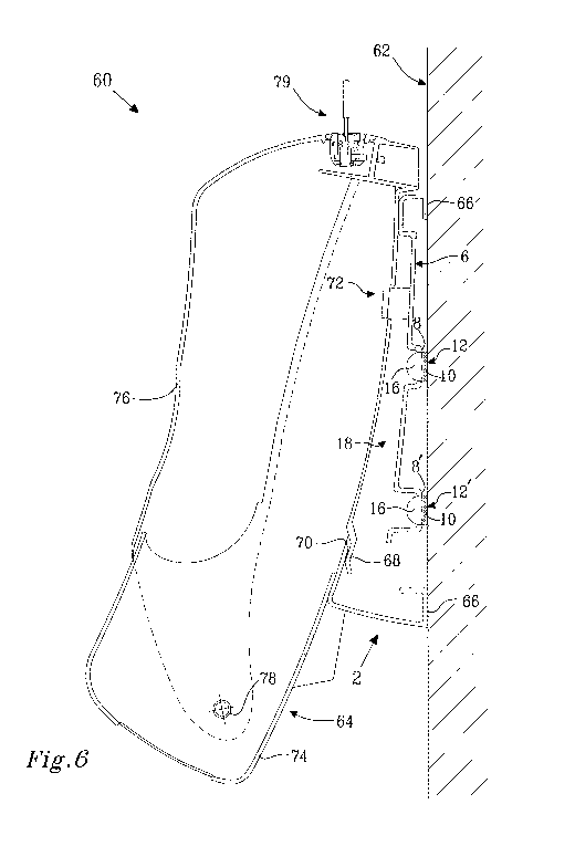
Fig. 6 illustrates a support device 60 according to embodiments. The support
device 60
comprises a base member 2 to be attached to a flat surface, such as a wall
surface 62.
The support device 60 comprises a cover member 64, forming a dispenser. In
these
embodiments the cover member 64 is a dispenser for sheet products in the form
of a
stack of e.g. sheets of paper or tissue. The base member 2 has a first side 6
and a
second side 18. The first side 6 faces the wall surface 62. The second side 18
is
opposite to the first side 6 and faces the cover member 64. The first side 6
is provided
with a first surface 8 and a further first surface 8'. The first surfaces 8,
8' are parallel to
the wall surface 62. In the base member 2, adjcent to each of the first
surfaces 8, 8',
there are arranged a through opening 12 and a further through opening 12',
respectively.
The base member 2 is attached to the wall surface 62 by means of two stretch
releasable adhesive strips 10. Pull tabs 16 of the stretch releasable adhesive
strips 10
extend at least partially through the through openings 12'.
The base member 2 is on the first side 6 provided with an outer surface
portion 66 which
runs along an outer periphery of the base member 2. The outer surface portion
66 is
CA 02817013 2013-05-03
WO 2012/078085
PCT/SE2010/051360
12
parallel with the first surfaces 8, 8'. The outer surface portion 66 abuts the
wall surface
62 when the base member is attached to the wall surface 62. Accordingly, the
outer
surface portion 66 projects farther out from the first side 6 than the first
and further first
surfaces 8, 8' in order for the stretch releasable adhesive strips 10 to fit
between the first
surfaces 8, 8' and the wall surface 62. The base member 2 may be resilient
between the
outer surface portion 66 and the first surfaces 8, 8' to allow a user to apply
pressure to
the first surfaces 8, 8' from the second side 18 when attaching the base
member 2 to the
wall surface 62 using the stretch releasable adhesive strips 10.
The cover member 64 is attached to the base member 2 by means of a projection
68
cooperating with an edge portion 70 of the base member 2 and a snap fit
releasable
connection 72. When the cover member 64 is connected to the base member 2 it
is in a
first position and covers the through openings 12, 12'. When the snap fit
connection 72
is released the cover member 64 may be removed from the base member 2 and thus
be
in a second position wherein the through openings 12, 12' are exposed.
The cover member 64 has a body part 74 and a lid 76 which is connected to the
body
part via a hinge 78. The cover member 64 comprises a lock 79 by means of which
the lid
76 may be locked against the body part 74. When the lock 79 is locked the
cover
member 64, may not be removed from the base member 2 to expose the through
openings 12, 12', i.e. when the lock 79 is in a closed state the cover member
2 is
maintained in the first position because access to the snap fit connection 72
is
prevented.
Fig. 7 illustrates schematically a support device 80 according to embodiments.
The
support device 80 comprises a base member 2 to be attached to a flat surface,
such as
a wall surface. The support device 80 comprises a cover member 82, forming a
dispenser. In these embodiments the cover member 82 is a dispenser for a
cleansing
agent such as liquid soap.
Fig. 8 illustrates schematically a support device 84 according to embodiments.
The
support device 84 comprises a base member (not visible) to be attached to a
flat
surface, such as a wall surface. The support device 84 comprises a cover
member 86,
forming a dispenser. In these embodiments the cover member 86 is a dispenser
for
CA 02817013 2013-05-03
WO 2012/078085
PCT/SE2010/051360
13
sheet products in the form of a roll of paper tissue which may be dispensed at
a lower
end of the dispenser.
Example embodiments described above may be combined as understood by a person
skilled in the art. It is also understood by those skilled in the art that the
through opening
for pulling a stretch releasable adhesive strip therethrough may be formed in
any kind of
flat, angled, or curved surface. A pull tab of a stretch releasable adhesive
strip may be
substantially flush with the flat surface and be pulled though the through
opening at the
time of releasing a base member from the flat surface. Alternatively, the pull
tab may
extend, at least partially, through the through opening already when the base
member is
mounted to the flat surface. The lock may be arranged to engage between the
cover
member and the base member.
A support device and/or a base member may be provided with the stretch
releasable
adhesive strip already attached to the first surface. On the side of the
stretch releasable
adhesive strip to be attached to a flat surface, there may be provided with a
protective
foil. Thus, for the support device/base member a suitable position on a flat
surface may
be tried out. When the support device/base member is to be attached to a flat
surface
the protective foil is removed from the stretch releasable adhesive strip and
the support
device/base member is pressed against the flat surface. Separate stretch
releasable
adhesive strips as such may be provided with protective foil on both adhesive
sides.
When a support device and/or a base member is removed from a flat surface the
old
stretch releasable adhesive strip is discarded. The support device and/or the
base
member may be reattached using a new stretch releasable adhesive strip.
Further examples of a support devices may be hook, hanger, knob, shelf, and
waste bin.
Therefore, it is to be understood that the foregoing is illustrative of
various example
embodiments and the invention is not to be limited to the specific embodiments
disclosed and that modifications to the disclosed embodiments, combinations of
features
of disclosed embodiments as well as other embodiments are intended to be
included
within the scope of the appended claims.
CA 02817013 2013-05-03
WO 2012/078085
PCT/SE2010/051360
14
As used herein, the term "comprising" or "comprises" is open-ended, and
includes one
or more stated features, elements, steps, components or functions but does not
preclude
the presence or addition of one or more other features, elements, steps,
components,
functions or groups thereof.
As used herein, the term "and/or" includes any and all combinations of one or
more of
the associated listed items.
As used herein, the common abbreviation "e.g.", which derives from the Latin
phrase
"exempli gratia," may be used to introduce or specify a general example or
examples of
a previously mentioned item, and is not intended to be limiting of such item.
If used
herein, the common abbreviation "i.e.", which derives from the Latin phrase
"id est," may
be used to specify a particular item from a more general recitation.
The terminology used herein is for the purpose of describing particular
embodiments
only and is not intended to be limiting of the invention. As used herein, the
singular forms
"a", "an" and "the" are intended to include the plural forms as well, unless
the context
clearly indicates otherwise.
Unless otherwise defined, all terms (including technical and scientific terms)
used herein
have the same meaning as commonly understood by one of ordinary skill in the
art to
which this invention belongs. It will be further understood that terms, such
as those
defined in commonly used dictionaries, should be interpreted as having a
meaning that
is consistent with their meaning in the context of the relevant art and will
not be
interpreted in an idealized or overly formal sense unless expressly so defined
herein.
It will be understood that when an element is referred to as being "on",
"coupled" or
"connected" to another element, it can be directly on, coupled or connected to
the other
element or intervening elements may also be present. In contrast, when an
element is
referred to as being "directly on", "directly coupled" or "directly connected"
to another
element, there are no intervening elements present.
It will be understood that although the terms first, second, third etc. may be
used herein
to describe various elements, components, regions, layers and/or sections,
these
CA 02817013 2013-05-03
WO 2012/078085
PCT/SE2010/051360
elements, components, regions, layers and/or sections should not be limited by
these
terms. These terms are only used top distinguish one element, component,
region, layer
or section from another element, component, region, layer or section. Thus, a
first
element, component, region, layer or section discussed herein could be termed
a
5 second element, component, region, layer or section without departing
from the
teachings of the present invention.
Spatially relative terms, such as "beneath", "below", "bottom", "lower",
"above", "top",
"upper" and the like, may be used herein for ease of description to describe
one
10 element's or feature's relationship to other element(s) or feature(s) as
illustrated in the
figures. It will be understood that the spatially relative terms are intended
to encompass
different orientations of the device in use or operation in addition to the
orientation
depicted in the figures. For example, if the device in the figures is turned
over, elements
described as "below" or "beneath" other elements or features would then be
oriented
15 "above" the other elements or features. Thus, the exemplary term "below"
can
encompass both an orientation of above and below. The device may be otherwise
oriented (rotated 90 degrees or at other orientations) and the spatially
relative
descriptors used herein interpreted accordingly. Also, as used herein,
"lateral" refers to a
direction that is substantially orthogonal to a vertical direction.
Example embodiments of the present invention have been described herein with
reference to cross-section illustrations that are schematic illustrations of
idealized
embodiments (and intermediate structures) of the invention. As such,
variations from the
shapes of the illustrations as a result, for example, of manufacturing
techniques and/or
tolerances are to be expected. Thus, embodiments of the present invention
should not
be construed as limited to the particular shapes of regions illustrated herein
but are to
include deviations in shape that result, for example, from manufacturing.