Note : Les descriptions sont présentées dans la langue officielle dans laquelle elles ont été soumises.
CA 02817638 2013 05 1C
WO 2012/063071
PCT/GB2011/052190
1
Modular Tool for Wellbore Cleaning
Technical Field
The technical field of the present invention relates to wellbore cleaning.
More particularly, the technical field of the present invention relates to
modular debris chambers of a debris extraction tool and a method for
collecting debris using such modular debris chambers.
Background Art
In recent years, attention has been given to the use of debris extraction
tools for wellbore cleaning. GB 2441246B discloses a device and method
for retrieving debris from a well using a venturi debris extraction tool and
may be useful background art for understanding the present invention.
Venturi debris extraction tools are used to create a downhole 'reverse
circulation' path to encourage loose debris to be drawn into a collecting
chamber. This chamber may be long and requires to be dismantled on the
rig floor when pulled from the well. The chamber often contains heavy
brine which is considered hazardous on skin contact. A system and/or
method for collecting this brine efficiently and any debris would be
advantageous.
In view of the prior art discussed above, there is a need to be able to
collect brine and/or debris with a debris extraction tool without losing too
much power of the downhole reverse circulation path. Preferably the
debris chambers should aid circulation within the debris extraction tool. It
is desirable that debris chambers should collect debris and allow for the
fluid to flow as freely as possible through the debris chambers while at the
same time allow solid debris to be collected in the debris chambers.
A further need is to avoid unwanted fluid (brine) spillage from a of debris
extraction tool. There is a need to be able to collect brine and/or debris in
a safe and controlled manner. This would allow for a cleaner environment
CA 02817638 2016-04-18
50233-22
2
and compliance with any regulations in this regard. Additionally, it is
desirable to avoid the
cumbersome arrangements from a technical and/or economical point of view.
Disclosure of the Invention
It is an object of the present invention to provide a modular tool for
wellbore cleaning.
According to some embodiments, there is provided an apparatus comprising a
plurality of
modular debris chambers, wherein each of the plurality of modular debris
chamber
comprises: a bucket for collecting debris, an inner flow tube being
concentrically arranged
within the bucket, and a deflector arranged at a lower end of the bucket and
being separate
from an inlet to the inner flow tube, the deflector of a first modular debris
chamber of the
plurality of modular debris chambers being configured to deflect a flow of
debris from the
inner flow tube of a second modular debris chamber of the plurality of modular
debris
chambers into the bucket of the second modular debris chamber, wherein the
second
modular debris chamber is connected to a lower end of the first modular debris
chamber.
According to some embodiments, there is provided a method for collecting
debris comprising:
interconnecting a plurality of modular debris chambers to form a debris
extraction tool,
wherein at least one of the plurality of modular debris chambers comprises: a
bucket for
collecting debris; an inner flow tube being concentrically arranged within the
bucket; and a
deflector arranged at a lower end of the bucket and being separate from an
inlet to the inner
flow tube, the deflector of a first modular debris chamber of the plurality of
modular debris
chambers being configured to deflect a flow of debris from the inner flow tube
of a second
modular debris chamber of the plurality of modular debris chambers into the
bucket of the
second modular debris chamber, wherein the second modular debris chamber is
connected
to a lower end of the first modular debris chamber; and reflecting fluid off a
shape of the
deflector allowing solid debris in the flow of debris to deflect off the shape
of the deflector into
the bucket of the second modular debris chamber.
According to some embodiments, there is provided an apparatus comprising: a
plurality of
modular debris chambers, wherein each of the plurality of modular debris
chambers
comprises: a bucket for collecting debris; an inner flow tube being
concentrically arranged
within the bucket; and a conduit fluidly connected to a lower end of the inner
flow tube, the
conduit being angled with respect to the inner flow tube.
CA 02817638 2015-07-15
50233-22
2a
According to one embodiment, a modular debris chamber for a debris
extraction tool may include a plurality of debris chambers. The modular
debris chamber may include a bucket for collecting debris, an inner flow
tube being concentrically arranged within the bucket, and a deflector
arranged in a lower end of the bucket for deflecting a flow of debris from
the inner flow tube of a subsequent modular debris chamber connectable
to a lower end of the modular debris chamber.
According to one embodiment, a distance between the deflector and a top
end opening of the inner flow tube of a subsequent modular debris
chamber is arranged to ensure debris carried in the fluid of the inner flow
tube of a subsequent modular debris chamber falls out into each bucket,
when the modular debris chamber and the subsequent modular debris
chamber are connected. The distance may be a function of the flow rate
of the fluid, the type of fluid, and the size of the tool. Preferably the
distance is from about 1 inch (2,5 cm) to about 5 inches (12,5 cm),
preferably about 3 inches (7,5 cm).
According to one embodiment, the deflector may include sealing means,
mounting means for mounting the deflector to the debris chamber, and a
conduit for the debris flow of the inner flow tube. The mounting means
may include at least three balls, an inner body comprising the conduit, and
a snap ring. The snap ring may locate the at least three balls to engage a
CA 02817638 2015-07-15
50233-22
3
groove of the debris chamber thereby mounting the deflector in the debris
chamber.
According to one embodiment, the sealing means holds the inner flow
tube and seals against the bucket. According to one embodiment, the
deflector may comprise a shape such that solid debris in the flow of debris
is deflected into the bucket of a subsequent modular debris chamber. The
central surface of the shape of the deflector may be above, in the direction
of the modular debris chamber, an inlet of the conduit. Preferably, the
shape may be a concave or a flat shape.
According to one embodiment, the deflector may comprise an inlet to the
inner flow tube and the inlet may be situated in a periphery of the
deflector. According to one embodiment, the modular debris chamber
may be part of a venturi debris extraction tool.
According to one embodiment, a method for collecting debris using such a
modular debris chamber may include a plurality of the modular debris
chambers interconnected to form the debris chambers of a debris
extraction tool, and reflecting fluid off the deflector allowing solid debris
in
the flow of debris to deflect off the deflector into the bucket of a
subsequent modular debris chamber.
Hereby a modular tool for wellbore cleaning is provided. The
embodiments collect efficiently brine and any debris. Due to the deflection
brine and/or debris may be collected with a debris extraction tool without
losing too much power of the downhole reverse circulation path. The
debris chambers may aid circulation within a debris extraction tool. The
debris chambers may collect debris and allow for the fluid to flow as freely
as possible through the debris chambers while at the same time allow
solid debris to be collected in the debris chambers.
Other technical advantages of the present disclosure will be readily
apparent to one skilled in the art from the following description.
CA 02817638 2013 05 1C
WO 2012/063071
PCT/GB2011/052190
4
Various embodiments of the present application obtain only a subset of
the advantages set forth. No one advantage is critical to the
embodiments. Any claimed embodiment may be technically combined
with any preceding claimed embodiment(s). The words "upper" and
"lower" are in relation to the orientation of a debris chamber in a debris
extraction tool in a wellbore.
Brief Description of Drawings
The accompanying drawings, which are incorporated in and constitute a
part of the specification, illustrate presently preferred embodiments of the
invention, and together with the general description given above and the
detailed description of the preferred embodiments given below, serve to
explain, by way of example, the principles of the invention.
FIG. 1 shows an exemplary embodiment of modular debris
chambers.
FIG. 2 shows an exemplary embodiment of a connection between
two debris chambers.
FIG. 3 shows an exemplary embodiment of an upper end of a
debris chamber.
FIG. 4 shows an exemplary embodiment of a lower end of a debris
chamber.
FIG. 5 shows an exemplary embodiment of a cross section A-A
from Fig 4.
FIG. 6 shows an exemplary embodiment of a lower end of a debris
chamber.
Modes for Carrying Out the Invention
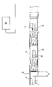
Fig 1 illustrates an exemplary embodiment of a debris chamber. Such a
debris chamber may be part of a debris extraction tool, and especially a
CA 02817638 2013 05 1C
WO 2012/063071
PCT/GB2011/052190
venturi debris extraction tool. The illustrated embodiment is a longitudinal
half-sectional view of a first debris chamber 11 connected to a second
debris chamber 12 connected to a third debris chamber 13. These debris
chambers 11-13 may be modular. The first debris chamber 11 is the
5 upper debris chamber when considering the debris chambers 11-13 as
part of a debris extraction tool positioned within a well. The third debris
chamber 13 is the lower debris chamber when considering the debris
chambers 11-13 as part of a debris extraction tool positioned within a well.
Any suitable amount of debris chambers may be used. The lowest debris
chamber may be connected to a bottom sub for extracting debris. The
upper debris chamber may be connected to a debris screening module
which in turn may be connected to an engine module 15. The engine
module is schematically illustrated in Fig 1. Such an engine module 15
may operate according to the venturi principle for circulating fluid for the
debris extraction tool. The engine module 15 may be used by the (venturi)
debris extraction tool to create a downhole reverse circulation path to
encourage loose debris to be drawn into the debris chambers 11-13.
The debris extraction tool may be utilised for retrieving debris from a well,
which may comprise part of a tool or tool string located in a borehole, or
other junk typically found downhole. The debris extraction tool may
therefore be utilised in a "fishing" operation, to retrieve part of a tool
which
has become lodged and stuck in a casing of a borehole. The debris
extraction tool may also be utilised for retrieving other debris such as
cement lumps, rocks, congealed mud, oxidation lumps, metal debris,
scale, slivers, shavings, burrs, water, dislodged mud cake residue, drill
cuttings or the like which has accumulated in the casing of a borehole, and
which is to be cleaned and removed prior to completion of a well. The
debris chambers may collect fluid, such as brine, comprising such debris.
When in operation, the debris extraction tool moves fluid, brine, within the
debris chambers. Debris may consequently be collected in the debris
CA 02817638 2013 05 1C
WO 2012/063071
PCT/GB2011/052190
6
chambers 11-13. The debris chamber 11, 12, or 13 in the exemplary
embodiment in Fig 1 comprises an inner flow tube 14. The inner flow tube
14 may be centrally arranged within the debris chamber 11, preferably
positioned concentric within the debris chamber 11 in the axial direction of
the debris chamber 11.
The fluid moves up through the debris extraction tool, up through the
debris chambers 11-13. When the fluid moves through a debris chamber,
the fluid may move through the inner flow tube 14. When fluid comprising
debris exits a top end opening 16 of the inner flow tube 14, the velocity of
the fluid slows and this allows the debris to fall into a bucket 17 of the
debris chamber.
According to one embodiment, the debris chambers are modularised.
Modular debris chambers 11-13 may be interconnected such that a
subsequent debris chamber 12 may be beneath the first modular debris
chamber 11, and a subsequent debris chamber 13 may be beneath the
second modular debris chamber 12. According to one embodiment, the
interconnection allow for the fluid to flow as freely as possible through the
debris chambers while at the same time allow solid debris to be collected
in the debris chambers.
Fig 2 shows an exemplary embodiment of a connection between two
debris chambers. The connection takes place by connecting a lower end
of an upper debris chamber with an upper end of a lower debris chamber.
Turning to Fig 3, an exemplary embodiment of an upper end of a debris
chamber 11 is illustrated. The top end opening 16 of the inner flow tube
14 ends within the bucket 17. An inner tube positioner 18 holds the inner
flow tube 14 within the debris chamber 11. The concentric position of the
inner flow tube 14 within the debris chamber 11 is indicated by the central
broken line.
CA 02817638 2013 05 1C
WO 2012/063071
PCT/GB2011/052190
7
Fig 4 illustrates an exemplary embodiment of a lower end of a debris
chamber 11. A deflector 20 may deflect fluid flow from the top end
opening 16 of the inner flow tube 14 of a subsequent modular debris
chamber and may ensure that debris carried in the fluid of the inner flow
tube 14 of a subsequent modular debris chamber falls out into each
bucket 17, respectively, when the modular debris chamber 11 is
connected with the subsequent modular debris chamber 12.
Fig 2 illustrates the connection of the two embodiments illustrated in Figs 3
and 4. A distance d between the deflector 20 and a top end opening 16 of
the inner flow tube 14 of a subsequent modular debris chamber is
arranged to ensure debris carried in the fluid of the inner flow tube 14 of a
subsequent modular debris chamber falls out into each bucket 17, when
the modular debris chamber 11 and the subsequent modular debris
chamber 12 are connected. The distance d may be a function of the flow
rate of the fluid, the type of fluid, and the size of the tool. According to
one
embodiment, the distance d is from about 1 inch (2,5 cm) to about 5
inches (12,5 cm), preferably about 3 inches (7,5 cm). The distanced may
be optimized in order to ensure that debris carried in the fluid of the inner
flow tube 14 will fall out into each of the buckets 17.
According to one embodiment, the deflector may include sealing means
21, mounting means 23, 24, and 25 for mounting the deflector to the
debris chamber, and a conduit 22 for the debris flow of the inner flow tube
14. According to one embodiment, the mounting means may include at
least three balls 23, an inner body 24 comprising the conduit 22, and a
snap ring 25. The snap ring 25 may locate the at least three balls 23 to
engage a groove 26 of the debris chamber 11 thereby mounting the
deflector 20 in the debris chamber 11. The sealing means 21 may hold
the inner flow tube 14 concentrically within the debris chamber. The
sealing means 21 may seal against an inner wall of the bucket 17. In this
CA 02817638 2013 05 1C
WO 2012/063071
PCT/GB2011/052190
8
way the deflector 20 may be located accurately and conveniently within
the debris chamber 11.
While Fig 4 shows an exemplary embodiment of a lower end of a debris
chamber 11, Fig 5 shows an exemplary embodiment of the cross section
A-A from Fig 4. The balls 23 are spaced 120 degrees from each other and
engage the groove 26 of the debris chamber 11. By mounting the
deflector 20 in this manner the distance d may be assured. This may
allow for a simple and effective way to mount the inner flow tube 14 in the
debris chamber 11.
According to one embodiment, the deflector 20 includes a shape 27 such
that solid debris in the flow of debris is deflected off the shape 27 of the
deflector 20 into the bucket 17 of a subsequent modular debris chamber.
A central area 29 of the surface of the shape of the deflector 20 is above,
in the direction of the modular debris chamber, an inlet 28 of the conduit
22. The central area 29 may be axially opposite the top end opening 16 of
the inner flow tube 14. This may effectively deflect solid debris in the fluid
into the bucket 17 while allow proper circulation of the fluid within the
debris extraction tool. The shape 27 may be a concave or a flat shape.
According to one embodiment, the deflector 20 may include an inlet 28 to
the inner flow tube 14. The inlet 28 may be situated in a periphery of the
deflector 20. The inlet 28 is preferably off center. The top end opening 16
of the inner flow tube 14 may not be opposite the inlet 28. This
arrangement promotes solid debris to deflect off the deflector and to be
collected in the bucket 17.
According to one embodiment, the modular debris chamber may be part of
a venturi debris extraction tool. Hereby a good circulation of the fluid
within the tool and its modular debris chambers is achieved without having
to use an excessive amount of fluid. Due to the deflection brine and/or
CA 02817638 2013 05 1C
WO 2012/063071
PCT/GB2011/052190
9
debris may be collected with a debris extraction tool without losing too
much power of the downhole reverse circulation path.
In use the modular debris chambers may be connected to form a long
collecting device. Any suitable numbers of modular debris chambers may
be connected. The plurality of debris chambers may form a collecting
device for a debris extraction tool, such as a venturi debris extraction tool.
A tool comprising the modular debris chamber overcomes the
disadvantages mentioned above and has the advantages mentioned
above.
According to one embodiment, a method for collecting debris may use a
modular debris chamber as disclosed above. A plurality of the modular
debris chambers 11, 12, and 13 may be interconnected to form the debris
chambers of a debris extraction tool. Fluid circulating may be reflected off
the deflector 20 allowing solid debris in the flow of debris to deflect off
the
deflector 20 into the bucket 17 of a subsequent modular debris chamber.
The subsequent modular debris chamber is the debris chamber just below
the deflector.
The method allows for an efficient circulation of the fluid within a tool,
especially within its modular debris chambers. The fluid moving out of the
inner flow tubes is deflected off the deflector ensuring debris is collected
in
the bucket. Due to the deflection, brine and/or debris may be collected
with a debris extraction tool without losing too much power of the
downhole reverse circulation path.
Industrial Applicability
The modular debris chamber and method discussed above provides a
modular tool for wellbore cleaning. The invention, therefore, is well
adapted to carry out the objects and attain the ends and advantages
mentioned, as well as others inherent therein. While the invention has
been described and is defined by reference to particular preferred
CA 02817638 2013 05 1C
WO 2012/063071
PCT/GB2011/052190
embodiments of the invention, such references do not imply a limitation on
the invention, and no such limitation is to be inferred. The invention is
capable of considerable modification, alteration, and equivalents in form
and function, as will occur to those ordinarily skilled in the pertinent arts.
5 The described preferred embodiments of the invention are exemplary only,
and are not exhaustive of the scope of the invention. Consequently, the
invention is intended to be limited only by the scope of the appended
claims, giving full cognizance to equivalents in all respects.