Note : Les descriptions sont présentées dans la langue officielle dans laquelle elles ont été soumises.
CA 02819707 2013-06-21
WO 2012/121711
PCT/US2011/027576
A METHOD FOR ACCELERATING START-UP FOR STEAM-
ASSISTED GRAVITY DRAINAGE (SAGD) OPERATIONS
TECHNICAL FIELD
This invention relates generally to a method for accelerating start-up for
steam
assisted gravity drainage (SAGD) operations.
BACKGROUND OF THE INVENTION
A variety of processes are used to recover viscous hydrocarbons, such as heavy
crude oils and bitumen, from underground deposits. There are extensive
deposits of
viscous hydrocarbons throughout the globe, including large deposits in the
Northern
Alberta tar sands, that are not recoverable with traditional oil well
production
technologies. A problem associated with producing hydrocarbons from such
deposits is
that the hydrocarbons are too viscous to flow at commercially viable rates at
the
temperatures and pressures present in the reservoir. In some cases, these
deposits are
mined using open-pit mining techniques to extract the hydrocarbon-bearing
material for
later processing to extract the hydrocarbons.
Alternatively, thermal techniques may be used to heat the reservoir fluids and
rock to produce the heated, mobilized hydrocarbons from wells. One such
technique for
utilizing a single well for injecting heated fluids and producing hydrocarbons
is described
in U.S. Patent No. 4,116,275, which also describes some of the problems
associated with
the production of mobilized viscous hydrocarbons from horizontal wells.
One thermal method of recovering viscous hydrocarbons using two vertically
spaced wells is known as steam-assisted gravity drainage (SAGD) process. The
SAGD
process is currently the only commercial process that allows for the
extraction of bitumen
1
CA 02819707 2013-06-21
WO 2012/121711
PCT/US2011/027576
at depths too deep to be strip-mined. For example, the estimated amount of
bitumen that
is available to be extracted via SAGD constitutes approximately 80% of the 1.3
trillion
barrels of bitumen in place in the Athabasca oilsands in Alberta, Canada.
Various
embodiments of the SAGD process are described in Canadian Patent No. 1,304,287
and
corresponding U.S. Patent No. 4,344,485. In the SAGD process, steam is pumped
through an upper, horizontal injection well into a viscous hydrocarbon
reservoir while the
heated, mobilized hydrocarbons are produced from a lower, parallel, horizontal
production well vertically spaced proximate to the injection well. The
injection and
production wells are typically located close to the bottom of the hydrocarbon
deposits.
The SAGD process is believed to work as follows. The injected steam creates a
"steam chamber" in the reservoir around and above the horizontal injection
well. As the
steam chamber expands upwardly and laterally from the injection well, viscous
hydrocarbons in the reservoir are heated and mobilized, especially at the
margins of the
steam chamber where the steam condenses and heats a layer of viscous
hydrocarbons by
thermal conduction. The heated, mobilized hydrocarbons (and steam condensate)
drain
under the effects of gravity towards the bottom of the steam chamber, where
the
production well is located. The mobilized hydrocarbons are collected and
produced from
the production well. The rate of steam injection and the rate of hydrocarbon
production
may be modulated to control the growth of the steam chamber to ensure that the
production well remains located at the bottom of the steam chamber and in a
position to
collect the mobilized hydrocarbons.
In order to initiate a SAGD production, thermal communication must be
established between an injection and a production SAGD well pair. Initially,
the steam
2
CA 02819707 2013-06-21
WO 2012/121711
PCT/US2011/027576
injected into the injection well of the SAGD well pair will not have any
effect on the
production well until at least some thermal communication is established
because the
hydrocarbon deposits are so viscous and have little mobility. Accordingly, a
start-up
phase is required for the SAGD operation. Typically, the start-up phase takes
about three
months before thermal communication is established between the SAGD well pair,
depending on the formation lithology and the actual inter-well spacing.
The traditional approach to starting-up the SAGD process is to simultaneously
operate the injection and production wells independently of one another to
circulate
steam. The injection and production wells are each completed with a screened
(porous)
casing (or liner) and an internal tubing string extending to the end of the
liner, forming an
annulus between the tubing string and casing. High pressure steam is
simultaneously
injected through the tubing string of both the injection and production wells.
Fluid is
simultaneously produced from each of the injection and production wells
through the
annulus between the tubing string and the casing. In effect, heated fluid is
independently
circulated in each of the injection and production wells during the start-up
phase, heating
the hydrocarbon formation around each well by thermal conduction. Independent
circulation of the wells is continued until efficient thermal communication
between the
wells is established. In this way, an increase in the fluid transmissibility
through the
inter-well span between the injection and production wells is established by
conductive
heating. The pre-heating stage typically takes about three to four months.
Once
sufficient thermal communication is established between the injection wells,
the upper,
injection well is dedicated to steam injection and the lower, production well
is dedicated
to fluid production. Canadian Patent No. 1,304,287 teaches that in a SAGD
start-up
3
CA 02819707 2013-06-21
WO 2012/121711
PCT/US2011/027576
process, while the injection and production wells are being operated
independently to
inject steam, the steam must be injected through the tubing string and fluid
collected
through the annulus, not the other way around. The patent discloses that if
steam is
injected through the annulus and fluid collected through the tubing string,
the steam
looses heat to both the formation and the tubing string (and its contents),
causing the
injected steam to condense before reaching the end of the well.
U.S. Patent No. 5,215,146 describes a method for reducing start-up time in
SAGD
operation by maintaining a pressure gradient between the upper and lower wells
with
foam. The pressure gradient forces the hot fluids from the upper well to the
lower well.
However, the method adds undesired costs and maintenance requirements due to
the need
to create downhole foam which is typically not required in a SAGD process.
WO 99/67503 teaches a method for initiating the recovery of hydrocarbons by
injecting heated fluids into the hydrocarbon deposit through an injection well
while
withdrawing fluids from a production well. The flow of the heated fluid
between the
injection and the production wells warms the reservoir fluids and rock between
the wells
to establish suitable conditions for recovery of hydrocarbons. However, the
method adds
undesired costs and maintenance requirements due to the need to inject heated
fluids
which are not typically required in a SAGD process.
Accordingly, an accelerated start-up method is needed to decrease the start-up
time for SAGD operation that does not require the injection of heated fluids
or the
creation of dowthole foam. Further, such a start-up method should accelerate
start-up of
SAGD operations without adversely impacting production from the SAGD well
pair.
4
CA 02819707 2013-06-21
WO 2012/121711
PCT/US2011/027576
SUMMARY OF THE INVENTION
This invention relates generally to a method to accelerate start-up of steam
assisted gravity drainage (SAGD) operations. In particular, the method reduces
the pre-
heating time (e.g., steam circulation time) required to establish thermal
communications
between an injector and a producer of a SAGD well pair.
The invention accelerates start-up of SAGD operations by quickly establishing
thermal communication between an injector and a producer of a SAGD well pair
during
the pre-heating stage (e.g., steam circulation period) and, thereby,
decreasing the pre-
heating time required to mobilize the hydrocarbons. The method relies on
solvent and
thermal benefits to reduce the viscosity of heavy crude oil or bitumen. The
solvent
benefits are provided by an initial solvent pre-soaking of the wellbores,
which reduces the
viscosity hydrocarbon deposits in the nearby formation. The thermal benefits
are
provided by conductive and convective heating of formation fluids and rock
between the
SAGD well pair through a pre-heating stage followed by short squeezing stage
of steam
injection. As a result, thermal communication is established more quickly
between the
SAGD well pair during the start-up period.
These and other objects, features, and advantages will become apparent as
reference is made to the following detailed description, preferred
embodiments, and
examples, given for the purpose of disclosure, and taken in conjunction with
the
accompanying drawings and appended claims.
BRIEF DESCRIPTION OF THE DRAWINGS
For a further understanding of the nature and objects of the present
inventions,
reference should be made to the following detailed disclosure, taken in
conjunction with
CA 02819707 2013-06-21
WO 2012/121711
PCT/US2011/027576
the accompanying drawings, in which like parts are given like reference
numerals, and
wherein:
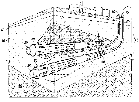
FIG. 1 is a perspective side view of an exemplary well pair for steam-assisted
gravity drainage (SAGD) production.
DETAILED DESCRIPTION
OF PREFERRED EMBODIMENTS OF THE INVENTIONS
The following detailed description of various embodiments of the present
invention references the accompanying drawings, which illustrate specific
embodiments
in which the invention can be practiced. While the illustrative embodiments of
the
invention have been described with particularity, it will be understood that
various other
modifications will be apparent to and can be readily made by those skilled in
the art
without departing from the spirit and scope of the invention. Accordingly, it
is not
intended that the scope of the claims appended hereto to be limited to the
examples and
descriptions set forth herein but rather that the claims be construed as
encompassing all
the features of patentable novelty which reside in the present invention,
including all
features which would be treated as equivalents thereof by those skilled in the
art to which
the invention pertains. Therefore, the scope of the present invention is
defined only by
the appended claims, along with the full scope of equivalents to which such
claims are
entitled.
The present invention uses numerical ranges to quantify certain parameters
relating to the invention. It should be understood that when numerical ranges
are
provided, such ranges are to be construed as providing literal support for
claim
limitations that only recite the lower value of the range as well as claim
limitations that
only recite the upper value of the range. For example, a disclosed numerical
ranges of
6
CA 02819707 2013-06-21
WO 2012/121711
PCT/US2011/027576
about 1 to 10 provides literal support for a claim reciting "greater than 1"
(with no upper
bounds) and a claim reciting "less than 10" (with no lower bounds).
An exemplary well pair for steam-assisted gravity drainage (SAGD) production
is
shown in FIG. 1. As shown in FIG. 1, the SAGD well pair 1 is drilled into a
formation 5
with one of the wells vertically spaced proximate to the other well. The
injection well 10
is an upper, horizontal well, and the production well 15 is a lower, parallel,
horizontal
well vertically spaced proximate to the injection well 10. In a preferred
embodiment, the
injection well 10 is vertically spaced about 4 to 10 meters above the
production well 15.
In an especially preferred embodiment, the injection well 10 is vertically
spaced about 5
to 6 meters above the production well 15. In a preferred embodiment, the SAGD
well
pair 1 is located close to the bottom of the oilsands 45 (i.e., hydrocarbon
deposits).
Generally, the oilsands 45 are disposed between caprock 40 and shale 50.
The SAGD well pair 1 comprises an injection well 10 and a production well 15.
The injection well 10 further comprises an injection borewell 20 and a first
production
tubing string 30, wherein the first production tubing string 30 is disposed
within the
injection borewell 20, and has a first return to surface capable of being shut-
in. Similarly,
the production well 15 further comprises a production borewell 25 and a second
production tubing string 35, wherein the second production tubing string 35 is
disposed
within the production borewell 25, and has a second return to surface capable
of being
shut-in. In a preferred embodiment, the injection 10 and production 15 wells
are both
completed with a screened (porous) casing (or liner) and an internal
production tubing
string 30, 35 extending to the end of the liner, and forming an annulus
between the tubing
string 30, 35 and wellbore (or casing) 20, 25.
7
CA 02819707 2013-06-21
WO 2012/121711
PCT/US2011/027576
During SAGD production, the upper well 10 (i.e., the injection well) injects
steam
60, possibly mixed with other solvents, and the lower well 15 (i.e., the
production well)
collects the heated, mobilized crude oil or bitumen 65 that flows out of the
formation 5
along with any water and/or solvents from the condensate of the injected
fluids. A start-
up phase is required for the SAGD operation. Initially, the steam 60 injected
into the
injection well 10 of the SAGD well pair 1 will not have any effect on the
production well
until at least some thermal communication is established because the
hydrocarbon
deposits are so viscous and have little mobility. The injected steam 60 and/or
solvents
eventually form a "steam chamber" 55 that expands vertically and laterally
into the
formation 5. The heat from the steam 60 reduces the viscosity of the heavy
crude oil or
bitumen 65, which allows it to flow down into the lower wellbore 25 (i.e., the
production
wellbore). The steam and/or solvent gases rise due to their relatively low
density
compared to the density of the heavy crude oil or bitumen 65 below. Further,
gases
including methane, carbon dioxide, and, possibly, some hydrogen sulfide are
released
from the heavy crude or bitumen, and rise in the steam chamber 55 to fill the
void left by
the draining crude oil or bitumen 65. The heated crude oil or bitumen 65 and
condensed
steam flows counter to the rising gases, and drains into the production
wellbore 25 by
gravity forces. The crude oil or bitumen 65 and water is recovered to the
surface by
pumps such as progressive cavity pumps that are suitable for moving high-
viscosity
fluids with suspended solids. The water may be separated from the crude oil or
bitumen
and recycled to generate more steam.
This invention relates generally to a method to accelerate the start-up of
SAGD
operations. In particular, the method reduces the pre-heating time (e.g.,
steam circulation
8
CA 02819707 2013-06-21
WO 2012/121711
PCT/US2011/027576
time) required to establish thermal communication between an injector 10 and a
producer
15 of the SAGD well pair 1. Specifically, the invention accelerates start-up
of steam
assisted gravity drainage (SAGD) operations by quickly establishing thermal
communication between an injector 10 and a producer 15 of the SAGD well pair 1
during
the pre-heating stage, and, thereby, decreasing the pre-heating time required.
The method
relies on solvent and thermal benefits to reduce the viscosity of heavy crude
oil or
bitumen 65. The solvent benefits are provided by an initial solvent pre-
soaking of the
wellbores, which reduces the viscosity of the hydrocarbon deposits in the
nearby of
formation. The thermal benefits are provided by conductive and convective
heating of
founation fluids and rock between the SAGD well pair 1 through a pre-heating
stage
followed by short squeezing stage of steam injection. As a
result, thermal
communication is established more quickly between the SAGD well pair 1 during
the
start-up period.
In an embodiment, a method for accelerating start-up for steam-assisted
gravity
drainage operations comprising the steps of forming a steam-assisted gravity
drainage
production well pair 1 within a formation 5 comprising an injection well 10
and a
production well 15. The injection well 10 further comprises an injection
wellbore (or
casing) 20; and a first production tubing string 30; wherein the first
production tubing
string 30 is disposed within the injection wellbore (or casing) 20, extending
to an end of
the wellbore 20 and forming an annulus between the tubing string 30 and the
wellbore (or
casing) 20, and wherein the tubing string 30 has a first return to surface
capable of being
shut-in. Similarly, the production well 15 further comprises a production
wellbore (or
casing) 25; and a second production tubing string 35, wherein the second
production
9
CA 02819707 2013-06-21
WO 2012/121711
PCT/US2011/027576
tubing string 35 is disposed within the production wellbore (or casing) 25,
extending to
an end of the wellbore 25 and forming an annulus between the tubing string 35
and the
wellbore (or casing) 25, and wherein the tubing string 35 has a second return
to surface
capable of being shut-in.
The method further comprises the step of beginning a pre-soaking stage by
soaking one or both of the wellbores 20, 25 of the SAGD well pair 1 with a
solvent.
When a new SAGD well pair 1 is drilled, there are usually several months of
idle/wait
time before steam and/or other facilities are available to the wells. This
invention makes
use of this idle period to pre-soak one or both of the wellbores 20, 25.
One or both of the wellbores 20, 25 may be pre-soaked with a liquid or a
gaseous
solvent that is soluble in heavy crude oil or bitumen 65. In the case of a
liquid solvent,
one or both of the wellbores 20, 25 are gravity fed or pumped with the liquid
solvent for
pre-soaking stage of a few months before SAGD production start-up. The liquid
solvent
may be selected from the group consisting of butane, pentane, hexane, diesel
and
mixtures thereof. The liquid solvent may be gravity fed or pumped through the
tubing
string 30, 35 or through the annulus formed between the tubing string 30, 35
and the
wellbore (or casing) 20, 25. In a preferred embodiment, the pre-soaking stage
is about 2
to 3 months. In an especially preferred embodiment, the pre-soaking stage is
no more
than about 4 months.
In the case of a gaseous solvent, one or both of the wellbores 20, 25 are
continuously injected with a gaseous solvent for a few months before start-up.
The
gaseous solvent may be combined with steam and may be selected from the group
consisting of air, carbon dioxide, methane, ethane, propane, natural gas and
mixtures
CA 02819707 2013-06-21
WO 2012/121711
PCT/US2011/027576
thereof. The gaseous solvent may be injected through the tubing string 30, 35
or through
the annulus formed between the tubing string 30, 35 and the wellbore (or
casing) 20, 25
because the solvent does not need to be heated. In a preferred embodiment, the
pre-
soaking stage is about 2 to 3 months. In an especially preferred embodiment,
the pre-
soaking stage is no more than about 4 months
In an embodiment, the method comprises the step of beginning a pre-heating
stage by heating the wellbores 20, 25 of the SAGD well pair 1. The wellbores
20, 25 are
pre-heated with a heated fluid or other heating mechanism for a few months
before
SAGD production start-up.
Heating methods include electric, electromagnetic,
microwave, radio frequency heating and steam circulation. In a preferred
embodiment,
the wellbores 20, 25 may be pre-heated with steam circulation for about 0.5 to
3 months.
The pre-heating may be completed in the same manner as with a conventional
SAGD
start-up. In a preferred embodiment, the steam is circulated in one or both of
the
wellbores (or casings) 20, 25 of an injector 10 and a producer 15 of the SAGD
well pair
1. In a preferred embodiment, the pre-heating stage is about 1 to 3 months. In
an
especially preferred embodiment, the pre-heating stage is about one month.
In an embodiment, the method comprises the step of beginning a squeezing stage
by injecting steam into the wellbores 20, 25 of the well pair 1. The wellbores
20, 25 are
injected with steam for a few days to a few weeks. In an embodiment, the pre-
heating is
stopped, and steam is injected into the wellbores 20, 25. In an embodiment,
the steam
circulation is stopped and the returns to surface of the injection well 10 and
production
well 15 production tubing strings 30, 35 are shut-in to force the injected
steam into the
11
CA 02819707 2013-06-21
WO 2012/121711
PCT/US2011/027576
formation 5. In a preferred embodiment, the squeezing stage is at least 1 day.
In an
especially preferred embodiment, the squeeze stage is about 1 to 30 days.
In an embodiment, the method comprises beginning steam-assisted gravity
drainage production. Once efficient thermal communication is established
between the
SAGD well pair 1, the upper well 10 is dedicated to steam injection, and the
lower well
15 is dedicated to fluid production. In a preferred embodiment, the steam
injection is
shut-in for the production 15 well, and the SAGD well pair 1 begins SAGD
production,
as discussed above.
Simulation studies using a numerical simulator such as CMG STARSTm
(2007.10) and a 3-D reservoir model have shown that pre-soaking the wellbores
with
solvents for about 2 to 3 months before pre-heating (e.g., steam circulation)
the wellbores
for a pre-heating stage of about one-month, and squeezing with steam injection
into the
formation for about 1 to 30 days can reduce the traditional start-up phase
from about 3 to
4 months to about 1 month without adversely impacting production from the SAGD
well
pair.
The benefit of pre-soaking with solvents before and squeezing with steam
injection after a month of pre-heating with steam circulation is two fold: 1)
the solvents
reduce the viscosity of the hydrocarbon deposits, and 2) the squeezed steam
introduces
convective heating, which is more efficient than conductive heating. With the
benefit of
solvent pre-soaking, the injected steam can penetrate the formation fluids
more quickly
and establish its injected volume in the formation more efficiently. The
injected steam
introduces the convection heat transfer mechanism into the formation, which
promotes
the thermal communication between the SAGD well pair. Accordingly, the present
12
CA 02819707 2013-06-21
WO 2012/121711
PCT/US2011/027576
invention reduces the traditional pre-heating period by about two months, and
accelerates
start-up for steam-assisted gravity drainage operations from a SAGD well pair
without
adversely impacting production from the well pair.
As used herein, the terms "a," "an," "the," and "said" means one or more.
As used herein, the term "and/or," when used in a list of two or more items,
means that any one of the listed items can be employed by itself, or any
combination of
two or more of the listed items can be employed. For example, if a composition
is
described as containing components A, B, and/or C, the composition can contain
A alone;
B alone; C alone: A and B in combination; A and C in combination; B and C in
combination; or A, B, and C in combination.
As used herein, the terms "comprising," "comprises," and "comprise" are open-
ended transition terms used to transition from a subject recited before the
term to one or
elements recited after the term, where the element or elements listed after
the transition
term are not necessarily the only elements that make up of the subject.
As used herein, the terms "containing," "contains," and "contain" have the
same
open-ended meaning as "comprising," "comprises," and "comprise," provided
above.
As used herein, the terms "having," "has," and "have" have the same open-ended
meaning as "comprising," "comprises," and "comprise," provided above.
As used herein, the terms "including," "includes," and "include" have the same
open-ended meaning as "comprising," "comprises," and "comprise," provided
above.
As used herein, the term "liquid" as applied to the treatment medium includes
liquid and dense phase states also known as critical and super critical
states.
13
CA 02819707 2013-06-21
WO 2012/121711
PCT/US2011/027576
As used herein, the term "simultaneously" means occurring at the same time or
about the same time, including concurrently.
14