Note : Les descriptions sont présentées dans la langue officielle dans laquelle elles ont été soumises.
CA 02820466 2013-06-26
SURGICAL APPARATUS INCLUDING SURGICAL BUTTRESS
BACKGROUND
Technical field
[0002] This application relates to a surgical apparatus, and more
particularly, to a
surgical buttress for use with a surgical stapling apparatus during operation
of the stapling
apparatus to apply a plurality of surgical staples to body tissue.
Background of Related Art
[0003] As medical and hospital costs continue to increase, surgeons are
constantly
striving to develop advanced surgical techniques. Advances in the surgical
field are often related
to the development of operative techniques which involve less invasive
surgical procedures and
reduce overall patient trauma. In this manner, the length of hospital stays
can be significantly
reduced, and, therefore, the hospital and medical costs can be reduced as
well.
[0004] Although the present disclosure includes, but is not limited to use
with endoscopic
surgery, endoscopic surgery is one of the truly great advances in recent years
to reduce the
1
CA 02820466 2013-06-26
invasiveness of surgical procedures. Generally, endoscopic surgery involves
incising through
body walls for example, viewing and/or operating on the ovaries, uterus, gall
bladder, bowels,
kidneys, appendix, etc. There are many common endoscopic surgical procedures,
including
arthroscopy, laparoscopy (pelviscopy), gastroentroscopy and
laryngobronchoscopy, just to name
a few. Typically, trocars are utilized for creating the incisions through
which the endoscopic
surgery is performed. Trocar tubes or cannula devices are extended into and
left in place in the
abdominal wall to provide access for endoscopic surgical tools. A camera or
endoscope is
inserted through a relatively large diameter trocar tube which is generally
located at the naval
incision, and permits the visual inspection and magnification of the body
cavity. The surgeon
can then perform diagnostic and therapeutic procedures at the surgical site
with the aid of
specialized instrumentation, such as, forceps, cutters, applicators, and the
like which are
designed to fit through additional cannulas. Thus, instead of a large incision
(typically 12 inches
or larger) that cuts through major muscles, patients undergoing endoscopic
surgery receive more
cosmetically appealing incisions, between 5 and 10 millimeters in size.
Recovery is, therefore,
much quicker and patients require less anesthesia than traditional surgery. In
addition, because
the surgical field is greatly magnified, surgeons are better able to dissect
blood vessels and
control blood loss. Heat and water loss are greatly reduced as a result of the
smaller incisions. In
order to address the specific needs of endoscopic and/or laparoscopic surgical
procedures,
endoscopic surgical stapling devices have been developed and are disclosed in,
for example, U.S.
Pat. Nos. 5,040,715 (Green, et al.); 5,307,976 (Olson, et al.); 5,312,023
(Green, et al.); 5,318,221
(Green, etal.); 5,326,013 (Green, et al.); and 5,332,142 (Robinson, et al.).
[0005] In many
surgical procedures, including those involved in open and endoscopic
surgery, it is often necessary to staple tissue. It is especially challenging
during endoscopic
2
CA 02820466 2013-06-26
surgery because of the small openings through which the stapling of tissues
must be
accomplished. Instruments for this purpose can include two elongated members
which are
respectively used to capture or clamp tissue. Surgical devices wherein tissue
is first grasped or
clamped between opposing jaw structure and then joined by surgical fasteners
are well known in
the art. Typically, one of the members carries a fastener cartridge which
houses a plurality of
staples arranged in at least two lateral rows while the other member has an
anvil that defines a
surface for forming the staple legs as the staples are driven from the staple
cartridge. The
fasteners are typically in the form of surgical staples but two part polymeric
fasteners can also be
utilized. Generally, the stapling operation is effected by cam bars or wedges
that travel
longitudinally through the staple cartridge, with the cam bars acting upon
staple pushers to
sequentially eject the staples from the staple cartridge. A knife can travel
between the staple
rows to longitudinally cut and/or open the stapled tissue between the rows of
staples. Such
instruments are disclosed, for example, in U.S. Pat. No. 3,079,606 and U.S.
Pat. No. 3,490,675.
[0006] A later
stapler disclosed in U.S. Pat. No. 3,499,591 applies a double row of
staples on each side of the incision. This is accomplished by providing a
disposable loading unit
in which a cam member moves through an elongate guide path between two sets of
staggered
staple carrying grooves. Staple drive members are located within the grooves
and are positioned
in such a manner so as to be contacted by the longitudinally moving cam member
to effect
ejection of the staples from the staple cartridge of the disposable loading
unit. U.S. Surgical, the
assignee of the present application, has manufactured and marketed endoscopic
stapling
instruments for several years. Examples of such instruments include the
Multifire ENDO GIATM
30 and Multifire ENDO GIA TM 60 instruments. Other examples of such staplers
are disclosed in
U.S. Patent Nos. 4,429,695 and 5,065,929.
3
CA 02820466 2013-06-26
[0007] In staplers of the general type described above, surgical buttress
material may be
used in combination with these instruments as reinforcement to staple lines to
further promote
proper staple formation while reducing twisting/malformation caused by any
misalignment or
unusual or non-uniform tissue. These instruments have provided significant
clinical benefits.
Nonetheless, improvements are possible, for example, by reducing the
complexity of
manufacture and/or application.
SUMMARY
[0008] According to one aspect, the present disclosure relates to an end
effector for a
surgical stapling apparatus. The end effector includes an anvil assembly and a
surgical buttress.
The anvil assembly includes an anvil body and an anvil plate that are
selectively connectable.
The anvil plate includes a bottom surface that defines a plurality of staple
forming pockets. The
surgical buttress includes a buttress body and a plurality of arms extending
from the body. The
surgical buttress may be formed of a non-woven material and may be made from a
material
selected from the group comprising polyglytone 6211, glycolide, caprolactone,
trimethylene
carbonate, lactide and combinations thereof.
[0009] The arms of the surgical buttress may extend from side edges of the
buttress body
and may be integrally formed with the buttress body. Notably, the arms of the
surgical buttress
may be foldable over one or both of a top and a bottom surface of the buttress
body. As can be
appreciated, the arms are disposable between a top surface of the anvil plate
and a bottom
surface of the anvil body to support the buttress body against the bottom
surface of the anvil
plate when the anvil plate and the anvil body are connected to one another.
The anvil body
4
CA 02820466 2013-06-26
defines one or more channels in a bottom surface of the anvil body for the
reception of one or
more of the arms of the surgical buttress.
[0010] According to one aspect, a surgical stapling apparatus includes a
first jaw
assembly, a second jaw assembly, a plurality of fasteners, and a surgical
buttress. The first jaw
assembly includes an anvil body and an anvil plate. The anvil plate defines a
plurality of
fastener forming pockets in a bottom surface thereof. The second jaw assembly
includes a
fastener cartridge defining a plurality of fastener retaining slots. The
plurality of fasteners is
disposed within the fastener slots and configured and dimensioned to be formed
by the fastener
pockets of the anvil plate upon a firing of the stapling apparatus. The
surgical buttress includes a
buttress body and a plurality of arms extending from the buttress body. As
appreciated, the
surgical buttress may be formed of a non-woven material and may be made from a
material
selected from the group comprising polyglytone 6211, glycolide, caprolactone,
trimethylene
carbonate, lactide and combinations thereof.
[0011] The arms of the surgical buttress may be integrally formed with the
buttress body
and may extend from side surfaces of the buttress body. The arms may be
foldable over one or
both of a top and a bottom surface of the buttress body. The arms may be
disposed between a
top surface of the anvil plate and a bottom surface of the anvil body to
support the buttress body
against the bottom surface of the anvil plate. The anvil body of the first jaw
assembly may define
one or more channels in the bottom surface thereof for the reception of one or
more of the arms
of the surgical buttress. The one or more arms may be released from the one or
more channels
upon a firing of the stapling apparatus.
[00121 The surgical stapling apparatus may include a knife assembly
including a knife
that is movable through one or both of the first and second jaw assemblies to
cut one or both of
the buttress body and the arms of the surgical buttress to facilitate a
release of at least the buttress
body from against the bottom surface of the anvil plate.
[00131 According to yet another aspect, a method of mounting a surgical
buttress to an
end effector of a surgical stapling apparatus includes providing an end
effector for a surgical
stapling apparatus. The end effector includes a first jaw assembly and a
second jaw assembly.
The first jaw assembly includes an anvil body and an anvil plate. The anvil
plate defines a
plurality of fastener forming pockets in a bottom surface thereof. The second
jaw assembly
includes a cartridge defining a plurality of fastener retaining slots for
retaining a plurality of
fasteners that are formed by the fastener forming pockets upon a firing of the
stapling apparatus.
The method involves providing a surgical buttress including a buttress body
and a plurality of
arms extending from the body and mounting the arms of the surgical buttress
between a top
surface of the anvil plate and the bottom surface of the jaw so that the
buttress body is disposed
adjacent the bottom surface of the anvil plate.
[00141 The method may include the step of positioning the arms of the
surgical buttress
within channels defined in the bottom surface of the anvil plate. One step may
include forming
the surgical buttress from a non-woven material. The method may involve
forming the surgical
buttress from a material selected from the group comprising polyglytone 6211,
glycolide,
caprolactone, trimethylene carbonate, lactide and combinations thereof.
6
CA 2820466 2019-11-12
[0014a] A
further embodiment of the invention provides a surgical stapling
instrument having an end effector, comprising: a staple cartridge assembly
having a
plurality of surgical staples arranged in rows; an anvil assembly including an
anvil body
and an anvil plate, the anvil plate including a bottom surface defining a
plurality of
staple forming pockets, the anvil body and the anvil plate being selectively
connectable
by securement features of the anvil body and the anvil plate, the anvil
assembly
including channels being defined between the anvil body and the anvil plate
when the
anvil body and the anvil plate are connected, the channels extending in a
lateral
direction across at least some of the plurality of staple forming pockets when
viewed
from a plane parallel to the anvil plate; and a surgical buttress including a
buttress body
and a plurality of arms extending from the body, the plurality of arms being
disposed
in the channels to support the buttress body against the bottom surface of the
anvil plate
when the anvil plate and the anvil body are connected to one another.
6a
CA 2820466 2019-11-12
CA 02820466 2013-06-26
BRIEF DESCRIPTION OF THE DRAWINGS
[0015] The above and other aspects, features, and advantages of the present
disclosure
will become more apparent in light of the following detailed description when
taken in
conjunction with the accompanying drawings in which:
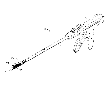
[0016] FIG. 1 is a perspective view of one embodiment of an endoscopic
surgical
stapling apparatus in accordance with the present disclosure;
[0017] FIG. 2 is an enlarged perspective view illustrating an end effector
of the presently
disclosed surgical stapling apparatus during a fastener applying operation as
fasteners are being
sequentially fired;
[0018] FIG. 3 is another perspective view of the end effector with a
surgical buttress
secured to an anvil assembly thereof;
[0019] FIG. 4 is a perspective view of the surgical buttress shown in FIG.
3;
[0020] FIG. 5 is a bottom perspective view, with parts separated, of the
anvil assembly of
the end effector shown in FIG. 3; and
[0021] FIG. 6 is a bottom perspective view, with parts assembled, of the
anvil assembly
shown in FIG. 5.
DETAILED DESCRIPTION OF EMBODIMENTS
[0022] As used herein, the term "clinician" refers to a doctor, a nurse, or
any other care
provider and may include support personnel. Particular embodiments of the
present disclosure
will be described herein with reference to the accompanying drawings. As shown
in the
7
drawings and as described throughout the following description, and as is
traditional when
referring to relative positioning on an object, the term "proximal" refers to
the end of the
apparatus that is closer to the clinician and the term "distal" refers to the
end of the apparatus that
is farther from the clinician. In the following description, well-known
functions or constructions
are not described in detail to avoid obscuring the present disclosure in
unnecessary detail.
[0023] In general, linear staplers, including open and endoscopic
devices, can have two
elongated members which are respectively used to capture or clamp tissue.
Typically, one of the
members carries a staple cartridge which houses a plurality of staples
arranged in at least two
lateral rows while the other member has an anvil that defines a surface for
forming the staple
legs as the staples are driven from the staple cartridge. Generally, the
stapling operation is
effected by cam bars that travel longitudinally through the staple cartridge,
with the cam bars
acting upon staple pushers to sequentially eject the staples from the staple
cartridge. A knife can
travel between the staple rows to longitudinally cut and/or open the stapled
tissue between the
rows of staples. Such an instrument is disclosed, for example, in U.S. Pat.
No. 6,202,914.
[0024] Some staplers apply a double row of staples on each side of the
incision. This is
accomplished by providing a disposable loading unit in which a cam member
moves through an
elongate guide path between two sets of staggered staple carrying grooves.
Staple drive
members are located within the grooves and are positioned in such a manner so
as to be
contacted by the longitudinally moving cam member to effect ejection of the
staples from the
staple cartridge of the disposable loading unit. An example of such a stapler
is disclosed in U.S.
Pat No. 5,065,929.
8
CA 2820466 2019-11-12
[0025] Some of the instruments described above were designed for use in
conventional
surgical procedures wherein surgeons have direct manual access to the
operative site. However,
in endoscopic or laparoscopic procedures, surgery is performed through a small
incision or
through a narrow cannula inserted through small entrance wounds in the skin.
In order to
address the specific needs of endoscopic and/or laparoscopic surgical
procedures, endoscopic
surgical stapling devices have been developed and are disclosed in, for
example, U.S. Pat. No.
5,865,361.
[0026] Referring now to the drawings, in which like reference numerals
identify identical
or substantially similar parts throughout the several views, FIG. 1
illustrates a surgical stapling
apparatus 10 that may be arranged for use with minimally invasive (i.e.,
endoscopic,
laparoscopic, etc.) or open stapling procedures. The surgical stapling
apparatus 10 includes a
housing 20 and an elongate member 30 that extends distally from the housing
20. A distal end of
the elongate member 30 supports a proximal end of an end effector 100 that
defines a
longitudinal axis "L" between proximal and distal ends of the end effector
100. The end effector
100 includes first jaw member or cartridge assembly 102 that is configured to
selectively receive
a staple cartridge 104 and second jaw member or anvil assembly 110. The
cartridge assembly
102 may be a single use loading unit. Indeed, the staple cartridge 104 houses
staples and/or
other surgical fasteners other than staples. The cartridge assembly 102 and/or
the staple
cartridge 104 may be selectively replaceable, either individually or
collectively.
[0027] With reference to FIG. 2, the staple cartridge 104 of the
cartridge assembly 102
includes a cartridge housing 106 including a tissue contacting surface 106a
having a plurality of
rows of staple retaining slots (also referred to herein as stapler slots and
fastener slots) 108
formed therein that house a plurality of fasteners or staples 70. With
reference to FIGS. 2 and 6,
9
CA 2820466 2019-11-12
CA 02820466 2013-06-26
the plurality of staples 70 may be sequentially formed in fastener forming
pockets 124 defined in
a tissue contacting surface 120b of the anvil assembly 110 upon a distal
advancement of a cam
bar and/or a sled 80 into a plurality of staple pusher members 90 as will be
described in greater
detail below.
[0028] Referring now to FIG. 3, anvil assembly 110 of the end effector 100
includes an
anvil plate 120, an anvil body 130, and a surgical buttress 140 (as used
herein, "surgical buttress"
includes a pledget, gasket, buttress, or staple line reinforcement structure).
The anvil assembly
110, or portions thereof, may be disposable or reusable.
[0029] As depicted in FIG. 4, the surgical buttress 140 includes a body
142, having a
substantially rectangular shape, and a plurality of arms 144. The body 142 and
the plurality of
arms 144 may be integrally formed or separately attachable. In particular, the
surgical buttress
140 includes a first arm 144a and a second arm 144b which extend laterally
from opposed side
edges or surfaces 142a, 144b of body 142 at a proximal region of body 142. A
third arm 144c
and a fourth arm 144d extend laterally from opposed side surfaces 142a, 142b
of body 142 at a
distal region of body 142. Of course, any number of arms 144 may be disposed
anywhere along
the side surfaces 142a, 142b of body 142.
[0030] One or more of the arms 144 may be disposed transverse or
substantially
transverse (i.e., non-orthogonal) to a longitudinal axis "L" that extends
through the body 142
between the proximal and distal ends of the body 142. As can be appreciated,
one more of the
arms 144 may be disposed at any suitable angle relative to the longitudinal
axis of the body 142
and may extend to any suitable distance from the side surfaces 142a, 142b of
the body 142.
Indeed, one or more of the arms 144 may have any suitable length, width and/or
thickness. Any
CA 02820466 2013-06-26
number of the arms 144 may be offset from, and/or aligned with, any number of
the other arms
144.
[0031] In
embodiments, the surgical buttress 140, or portions thereof, may be made from
biodegradable materials selected from the following group: natural collagenous
materials, cat
gut, and synthetic resins including those derived from alkylene carbonates,
trimethylene
carbonate, tetramethylene carbonate, caprolactone, valerolactone, dioxanone,
polyanhydrides,
polyesters, polyacrylates, polymethylmethacrylates, polyurethanes, glycolic
acid, lactic acid,
glycolide, lactide, polyhydroxy butyrates, polyorthoester, polyhydroxy
alkanoates,
homopolymers thereof, and copolymers thereof. In embodiments, the surgical
buttress 110, or
portions thereof, may be made from non-biodegradable materials selected from
the following
group: polyolefins, polyethylene, polydimethylsiloxane, polypropylene,
copolymers of
polyethylene and polypropylene, blends of polyethylene and polypropylene,
ultra high molecular
weight polyethylene, polyamides, polyesters,
polyethylene terephthalate,
polytetrafluoroethylene, polyether-esters, polybutester, polytetramethylene
ether glycol, 1,4-
butanediol, and polyurethanes. In embodiments, the surgical buttress 140, or
portions thereof,
may be a non-woven material selected from the group including polyglytone
6211, glycolide,
caprolactone, trimethylene carbonate, lactide and combinations thereof.
[0032] Turning
now to FIGS. 5-6, the anvil body 130 defines a first transverse channel
132 and a second transverse channel 134 therethrough that align with one or
more of the arms
144 of the surgical buttress 140 when the surgical buttress 140 is properly
aligned with the anvil
body 130. The first and second channels 132, 134 are dimensioned to receive
one or more arms
144 of the surgical buttress 140 to support the arms 144 of the surgical
buttress 140 between the
anvil body 130 and the anvil plate 120 while maintaining the body 142 of the
surgical buttress
11
CA 02820466 2013-06-26
140 positioned adjacent to a bottom or tissue contacting surface 120b of the
anvil plate 120. In
particular, the first and second channels 132, 134 are recessed from a bottom
surface 130b of the
anvil body 130 and are disposed in a longitudinally spaced apart relationship
along the anvil
body 130.
[0033] Anvil body 130 may include an anvil body securement feature 136 that
mates
with an anvil plate securement feature 122 to secure the anvil body 130 and
the anvil plate 120
together when engaged. As can be appreciated, the one or more securement
features may
include any suitable mechanical or chemical feature. For example, as
illustrated in FIG. 6, a pin
122a may extend from a top surface 120a of anvil plate 120 to engage with an
aperture 136a
defined within anvil body 130. Other mechanical arrangements may include hook-
and-loop
fasteners, friction-fit engagement, and/or snap-fit engagement In embodiments,
an adhesive
and/or a magnetic material may be included on any suitable surface of the
anvil body 130 and/or
anvil plate 120 to facilitate securement of the anvil body 130 and the anvil
plate 120.
[0034] Notably, surgical buttress 140, or portions thereof, may be operably
connected to
the anvil assembly 110, or portions thereof, via any suitable chemical or
mechanical feature (e.g.,
adhesive, magnet, hook-and- loop, snap-fit, straps, threads, welding, etc.).
[0035] To assemble, the surgical buttress 140 is positioned adjacent the
anvil plate 120
such that the body 142 of the surgical buttress 140 is disposed
against/adjacent the bottom
surface 120b of the anvil plate 120, and such that the arms 144 of the
surgical buttress 140 are
folded around side surfaces 120c, 120d of the anvil plate 120 to position the
arms 144 along the
top surface 120a of the anvil plate 120. In this regard, the anvil plate 120
may be secured to the
anvil body 130 via the securement features 122, 136 so that the arms 144 of
the surgical buttress
12
CA 02820466 2013-06-26
are disposed within the channels 132, 134 between the bottom surface 130b of
the anvil body
130 and the top surface 120a of the anvil plate 120. Suitably, the anvil plate
120 may be secured
to the anvil body 130 prior to the attachment of the surgical buttress 140. In
this regard, the
surgical buttress 140 is positioned adjacent to the anvil plate 120 so that
the arms 144 of the
surgical buttress 140 may be inserted within the channels 132, 134 to mount
the body 142 of the
surgical buttress 140 adjacent to the bottom surface 120b of anvil plate 120
so that the body 142
of the surgical buttress 140 is disposed in contact with the bottom surface
120b of the anvil plate
120.
[0036] Referring again to FIGS. 5-6, upon proper attachment to the anvil
plate 120
and/or the anvil body 130, the body 142 of the surgical buttress 140 may
extend between
proximal and distal portions of the anvil plate 120. In particular, the body
142 of the surgical
buttress 140 may substantially overlie some or all of the fastener forming
pockets 124 (FIG. 6)
defined in the anvil plate 120.
[0037] After clamping the first and second jaw members 102, 110 of the
surgical stapling
apparatus 10 against tissue of a patient, the surgical stapling apparatus 10
may then be fired to
deploy the fasteners 70 through the fastener slots 108 of the staple cartridge
104. Upon firing,
the fasteners 70 pass through the fastener slots 108 and the legs of the
fasteners 70 penetrate
through the tissue clamped by the jaw members 102, 110 and the body 142 of the
surgical
buttress 140. The fasteners 70 are then formed against the fastener forming
pockets 124 of the
anvil plate 120, thereby affixing the body 142 of the surgical buttress 140 to
the clamped tissue.
Concomitantly therewith, a knife (not shown) translatably disposed within the
end effector 100
cuts through the tissue clamped between the jaw members 102, 110, through at
least a portion of
13
CA 02820466 2013-06-26
the body 142 of the surgical buttress 140. In certain embodiments, the knife
can be configured
and arranged to cut through the body 142 prior to firing.
[0038] The surgical buttress 140 disengages from the cartridge housing 106
of the staple
cartridge 104 so that the body 142 and/or the arms 144 of the surgical
buttress 140 may remain
attached to the tissue via the fasteners 70. Alternatively, the arms 144
and/or body 142 of the
surgical buttress 140 can be cut with shears, or can include perforations or
frangible features for
separating any suitable portion of the surgical buttress 140 (i.e., arms 144)
from other portions of
the surgical buttress 140 (i.e., body 142).
[0039] If further application or use of a surgical buttress is necessary, a
new surgical
buttress 140 may be mounted onto the anvil assembly 110, as described above.
The user may
then repeat a fastening process. It is further contemplated that, if desired,
a clinician may
remove surgical buttress 140 from anvil assembly 110 prior to a use of
surgical stapling
apparatus 10.
[0040] Alternatively or additionally, any suitable surgical buttress may be
positioned on
cartridge assembly 102 before or after firing as can be appreciated.
[0041] Persons skilled in the art will understand that the structures and
methods
specifically described herein and illustrated in the accompanying figures are
non-limiting
exemplary embodiments, and that the description, disclosure, and figures
should be construed
merely as exemplary of particular embodiments. It is to be understood,
therefore, that the
present disclosure is not limited to the precise embodiments described, and
that various other
changes and modifications may be effected by one skilled in the art without
departing from the
scope or spirit of the disclosure. Additionally, it is envisioned that the
elements and features
14
, .
CA 02820466 2013-06-26
illustrated or described in connection with one exemplary embodiment may be
combined with
the elements and features of another without departing from the scope of the
present disclosure,
and that such modifications and variations are also intended to be included
within the scope of
the present disclosure. Accordingly, the subject matter of the present
disclosure is not to be
limited by what has been particularly shown and described.