Note : Les descriptions sont présentées dans la langue officielle dans laquelle elles ont été soumises.
IMPROVED MODULAR SYSTEM FOR CONTINUOUSLY INSULATING
EXTERIOR WALLS OF A STRUCTURE AND SECURING EXTERIOR
CLADDING TO THE STRUCTURE
Be it known that we, Douglas James Knight, a citizen of the United States and
a
resident of Sevens County in the State of Washington, whose Post Office
address is
28308 North Cedar Road, Deer Park, WA 99006; and Brian Nelson, a citizen of
the
United States and a resident of Spokane County in the State of Washington,
whose Post
Office Address is 28308 North Cedar Road, Deer Park, WA 99006; have each
invented
all of the new and useful improvements in an IMPROVED MODULAR SYSTEM
FOR CONTINUOUSLY INSULATING EXTERIOR WALLS OF A STRUCTURE
AND SECURING EXTERIOR CLADDING TO THE STRUCTURE of which the
following is a specification.
1
CA 2820970 2019-12-27
CA 02820970 2013-07-11
II. BACKGROUND OF INVENTION
IIA. RELATED APPLICATIONS
[0001] There are no Patent Applications related hereto previously filed in
the United States of America nor in any foreign country.
IIB. FIELD OF INVENTION
[0002] This invention relates to static structures, and more particularly to
an improved modular system for mounting and supporting
continuous thermal insulation and exterior cladding on a structure
while providing a rain screen between the continuous thermal
insulation and the exterior cladding, and eliminating thermal breaks
and eliminating thermal conductivity from the exterior of the
structure to the interior of the structure, and visa-versa.
2
CA 02820970 2013-07-11
IIC. BACKGROUND AND DESCRIPTION OF PRIOR ART
[0003] It is well known in the construction field to build structure walls
with
plural spaced apart parallel vertical studs of wood or metal. The
studs communicate, at a bottom end portion with a wall plate that is
anchored to a lower support which may be a building foundation,
and at an upper end portion with a ceiling plate that extends
generally perpendicular to the studs and parallel with the wall plate.
A weather resistive barrier formed of material such as asphalt
impregnated paper, plastic sheeting, building wrap or similar
product may be attached to exterior facing edges of the wall studs,
extending from stud to stud and from floor plate to ceiling plate.
The weather resistive barrier inhibits flow of air and moisture
through any gaps that may exist in the wall assembly.
[0004] Sheathing formed of materials such as, but not limited to, plywood,
oriented strand board (OSB), wafer board, metallic sheeting,
lapboard, gypsum sheathing and the like, may be fastened to the
3
CA 02820970 2013-07-11
outward facing edges of the wall studs outward of the weather
resistive barrier. The sheathing also typically extends from wall stud
to wall stud and from the wall plate to the ceiling plate. The
sheathing may provide the exterior surface of the structure or may
itself be covered with another exterior cladding, exterior covering or
exterior coating.
[0005] Services such as plumbing, electrical, tele-communications and the
like may be provided for by forming generally horizontally aligned
holes in the studs and placing conduit, or the like, through the
horizontally aligned holes. Thereafter, wiring, pipes and the like
may be threaded into and through the conduit or directly through
the generally horizontally aligned holes.
[0006] Commonly, interior insulation is installed directly against interior
facing surface of the weather resistive barrier in the spaces between
the wall studs extending from the floor plate to the ceiling plate.
The insulation may be of various forms including fiberglass batting,
mineral wool, recycled paper, cellulose or the like. The object is to
4
CA 02820970 2013-07-11
"fill" the space between the wall studs to limit thermal transfer from
the interior of the structure wall to the exterior of the structure wall,
and visa versa depending upon the structure's interior operating
conditions and the outside climate.
[0007] A vapor barrier such as plastic sheeting or the like may be attached
to the interior facing edges of the wall studs extending from wall
stud to wall stud and from the ceiling plate to the floor plate
enclosing the insulation between the wall studs and between the
inner vapor barrier and outer weather resistive barrier.
[0008] Interior sheathing, such as drywall, gypsum board, paneling or the
like is attached to the inward facing edge portions of the wall studs,
the floor plate and the ceiling plate and access holes are cut in the
interior sheathing to provide access to the electrical boxes,
plumbing fittings and the like.
[0009] One drawback to such wall assemblies and framing methods is that
such methods create thermal bridges in the structure's walls which
decrease the effectiveness of the insulation and allows thermal
CA 02820970 2013-07-11
energy to be conducted through the wall assembly from the inside to
the outside, and from the outside to the inside depending upon the
outside temperatures and the inside operating conditions.
[0010] Although insulation is provided between the wall studs between the
exterior sheathing and the interior sheathing, the studs themselves
provide little insulative value and walls formed by such methods are
not thermally efficient because thermal transfer occurs through the
wall studs. When metal wall studs are used, such as those
commonly used in commercial construction, the effectiveness of
insulation between the metal wall studs may be reduced by more
than fifty percent (50%).
[0011] For example, a wall assembly having exterior sheathing and interior
sheathing supported by plural parallel spaced apart 2" x 6" wood
wall studs therebetween and having 1-21 rated fiberglass batting
type insulation filling the spaces between the wood wall studs has an
effective R-rating of approximately R-18 due to the thermal transfer
through the wood wall studs. If the
same wall assembly is
6
CA 02820970 2013-07-11
constructed using steel wall studs between the exterior cladding and
the interior sheathing the effective R-value drops to approximately
R-8 because of the thermal loss through the steel wall studs.
[0012] Even when additional layers of thermal insulation are placed on the
exterior of a structure, the thermal effectiveness of such insulation is
reduced by the common practice of attaching exterior cladding
directly to the outward facing surface of the insulation with metal
framing elements that penetrate through the insulation thereunder
to attach to the underlying wall studs for structural support.
[0013] Adding insulation to the exterior of a structure is also known to
cause condensation within the wall, which occurs when moisture-
laden air comes into contact with a surface having a temperature
below the dew-point temperature of the moisture-laden air. In a
wall assembly, condensation usually occurs during the cold weather
months on the inward facing surface (back side) of the exterior
cladding when warm moisture laden air from the interior of the
structure penetrates the wall assembly and contacts, the cold inward
7
CA 02820970 2013-07-11
facing surface of the exterior cladding. In warm weather months,
the condensation usually forms on the outward facing surface of the
insulation by warm air penetrating the wall from the outside and
contacting the cooler outward facing surface of the insulation which
can lead to moisture saturation of the insulation which degrades the
effectiveness of the insulation. Without
proper design and
engineering, attaching insulation directly to the exterior of a
structure can be ineffective and can even be detrimental to the
useful life of the wall assembly.
(0014] Another drawback to such construction methods is the limited
number of options for cladding the exterior of a light-frame
structure. Although some exterior claddings are available, such as
lap board, metal siding, paneling and the like, such cladding is
typically limited to light-weight coverings that can be supported by
hanger-type wall attachments. Cladding exterior walls with heavy
materials such as brick, stone and the like has previously been
difficult because the weight of such coverings must be supported by
8
CA 02820970 2013-07-11
the wall attachments. Overcoming this difficulty leads to additional
costs and expenses for larger foundations for vertical support,
stronger beams for horizontal support and additional labor costs.
[0015] A further drawback to such construction methods is the limited
ability to refurbish existing structures by changing the exterior.
Generally, when an existing structure is "re-clad" the options
available are limited to replacing the existing cladding, or fastening
a light weight cladding over the top of the existing cladding.
Unfortunately, at times this is not feasible because the existing
cladding is too deteriorated to allow stable attachment of the new
cladding system. Further,
in some instances the vertical
"plumbness" or planar nature of an exterior wall might be so poor
that it is not feasible or practical to attach a new exterior cladding to
the existing structure. Finally, attaching a new exterior cladding has
the ability to alter the building's "footprint" sufficiently to cause
property line set-back problems by extending the building's walls
outwardly.
9
CA 02820970 2013-07-11
[0016] Evolving construction standards with increased emphasis on energy
efficiency, "being green" and limiting greenhouse gas emissions have
required construction methods and techniques to likewise change to
focus on the energy efficiency of structures. One way to increase the
energy efficiency of a structure is to add insulation to the exterior of
the structure. Another is to minimize, or if possible eliminate
thermal bridges that allow energy loss. A third is to improve
moisture management which improves durability and thermal
performance of the wall assembly. An even more effective solution
is to do all three; add insulation to the exterior of a structure while
effectively managing moisture and eliminating and minimizing
thermal bridges. The combination of these efforts is known as
"continuous insulation" which is defined in various building codes,
such as, but not limited to, ASHREA 90.1 as insulation that is
uninterrupted by framing members, except fasteners (screws, nails)
and is installed either inboard or outboard of the wall.
CA 02820970 2013-07-11
[001 7] The precise definition of "Continuous Insulation" as set forth in the
proposed Seattle Energy Code of 29 April 2010 with which
Applicants are most familiar, defines continuous insulation as
follows:
CONTINUOUS INSULATION (CI): Insulation that is continuous
across all structural members without thermal bridges other than
fasteners (i.e., screws and nails) and service openings. It is
installed on the interior or exterior or is integral to any opaque
surface of the building envelope. Insulation installed between
metal studs, z-girts, z-channels, shelf angles, or insulation with
penetrations by brick ties and offset brackets, or any other similar
framing is not considered continuous insulation, regardless of
whether the metal is continuous or occasionally discontinuous or
has thermal break material.
[0018] What is needed is a system that allows exterior cladding to be
installed on new structures and onto existing structures, and allows
the walls to be insulated having a high degree of thermal insulation
11
CA 02820970 2013-07-11
while minimizing or eliminating thermal bridges and moisture
management problems. The system must accommodate a variety of
exterior claddings and must allow the structure to be provided with
a new appearance, including an appearance of being constructed a
brick, stone or the like. The system must comply with evolving
construction standards including the new ASHRE 90.1 standards,
including the standards for continuous installation. The system
must be economical and efficient and provide sufficient flexibility
and structural integrity to allow a user to clad the exterior of a
structure as desired and simultaneously preserve the desirable
features of known light frame construction methods and systems.
[0019] Our system overcomes various drawbacks of known construction
apparatus, methods and techniques by providing an improved
modular system that preserves user flexibility in the exterior
cladding of a structure and maximizes the insulative capabilities by
providing a continuously insulated structure having no or minimal
thermal bridges that allow thermal energy loss.
12
CA 02820970 2013-07-11
[0020] Our system provides unique Tek-brackets that are attached to the
underlying structure in a manner that the Tek-brackets are thermally
isolated from the underlying structure to prevent creation of thermal
bridges. The
configuration of the Tek-brackets secures
nonflammable/noncombustible mineral wool insulation immediately
adjacent to the structure and provides a support for exterior
cladding which may be either directly or indirectly mounted thereto.
[0021] A wall panel hanging system fastened to outward end portions of the
Tek-brackets provides a generally "U" shaped vertical rail or
horizontal rail upon which exterior cladding or wall panels may be
releasably secured. A desired exterior cladding may be fastened to
exterior facing portions of the vertical rails and/or horizontal rails.
Corner elements carrying complimentary sections of the desired
exterior cladding are supported by the system at the structure
corners.
[0022] A rain screen between inner surface of the exterior cladding and the
outer surface of the insulation provides a pressure equalized drain
13
CA 02820970 2013-07-11
cavity that prevents moisture from passing from the exterior into the
wall assembly, reduces condensation, and properly manages
moisture. The pressure equalized drain cavity is configured to
comply with fire standards to prevent formation of a "chimney"
between the inner surface of the exterior wall cladding and the outer
surface of the insulation.
[0023] Thermal isolators reduce thermal transfer between interconnecting
elements by preventing metal to metal connections and the Tek-
brackets provide a tapered down "bottle neck" that further reduces
thermal transfer between the exterior cladding and the underlying
structure and maximizes the effectiveness of the insulation.
[0024] Our system increases the "effective R Value" of structures by
providing a more energy efficient wall structure that loses less heat
through thermal conduction through the wall structure.
[0025] Our system reduces moisture condensation within the wall assembly
effectively manages moisture and minimizes energy losses related to
thermal bridging.
14
CA 02820970 2013-07-11
[0026] Our system meets and exceeds evolving and changing building
codes and regulations, such as but not limited to ASHRAE 90.1
standards which are the baseline energy efficiency guidelines used
worldwide for promotion of energy efficiency, energy conservation
and "greenness".
[0027] Our system allows the exterior of a structure to be clad in a material
that has the appearance and texture of masonry, brick, stone and
the like, but the cladding system does not have the weight of such
construction and therefore the foundation and other underlying
support structures of the building need not have the massiveness
nor the cost and expense of support structures that would be
necessary to support construction with such heavy materials.
[0028] Our invention does not reside in any one of the identified features
individually, but rather in the synergistic combination of all of its
structures, which give rise to the functions necessarily flowing
therefrom as hereinafter specified and claimed.
CA 02820970 2013-07-11
III. SUMMARY
[0029] An improved modular system for continuously insulating exterior
walls of a structure and securing exterior cladding to the structure
provides thermally isolated Tek-brackets secured to a structure
exterior wall that positionally maintain non-flammable mineral wool
insulation adjacent the structure wall and provide a means for
mounting exterior wall cladding to the structure. Wall panels and
corner elements carrying exterior wall cladding elements mount
directly or indirectly to thermally isolated vertical rails or thermally
isolated horizontal rails carried by the Tek-brackets spaced apart
from the exterior wall.
[0030] In providing such an improved modular system it is:
[0031] a principal object to provide a modular system for insulating a
structure wall and supporting exterior wall cladding.
[0032] a further object to provide a modular system that minimizes thermal
transfer from the exterior of a wall to the interior of a wall and from
the interior of a wall to the exterior of a wall.
16
CA 02820970 2013-07-11
[0033] a further object to provide a modular system that complies with
building codes for energy efficiency, thermal energy savings and
"greenness".
[0034] a further object to provide a modular system that thermally isolates
the Tek-brackets from the structure wall.
[0035] a further object to provide a modular system that prevents
penetration and passage of moisture into the structure wall.
[0036] a further object to provide a modular system that may be installed
on a new structure.
[0037] a further object to provide a modular system that may be installed
on an existing structure.
[0038] a further object to provide a modular system that supports a variety
of exterior claddings.
[0039] a further object to provide a modular system that decreases the cost
of insulating a structure and increases the effectiveness of the
insulation.
17
CA 02820970 2013-07-11
[0040] a further object to provide a modular system that allows a
structure's exterior walls to be re-plumbed to vertical.
[0041] a further object to provide a modular system that will support
exterior wall cladding panels.
[0042] a further object to provide a modular system that uses
interchangeable parts and is mountable vertically as well as
horizontally.
[0043] a further object to provide a modular system that uses vertical rails
and horizontal rails that are interchangeable.
[0044] a further object to provide a modular system wherein the length of
the Tek-brackets may be adjusted to accommodate differing
thicknesses of insulation.
[0045] a further object to provide a modular system that is completely
thermally isolated and the satisfies the definitions of "continuous
insulation".
[0046] a further object to provide a modular system that is ASHRE 90.1
compliant.
18
CA 02820970 2013-07-11
[0047] a further object to provide such a modular system that supports
brick cladding.
[0048] a further object to provide a modular system that supports masonry
cladding.
[0049] a further object to provide a modular system that supports stone
cladding.
[0050] a further object to provide a modular system that supports metallic
cladding.
[0051] a further object to provide modular system that eliminates the need
for massive foundations to support the weight of brick, stone and
masonry cladding.
[0052] a further object to provide a modular system that reduces
condensation within the wall assembly and effectively manages
moisture within the wall assembly.
[0053] a still further object to provide a modular system that meets building
standards for continuous insulation.
19
CA 02820970 2013-07-11
[0054] A still further object to provide a modular system that utilizes non-
flammable insulation to reduce fire risk.
[0055] Other and further objects of our invention will appear from the
following specification and accompanying drawings which form a
part hereof. In carrying out the objects of our invention it is to be
understood that its structures and features and steps are susceptible
to change in design and arrangement and order with only one
preferred and practical embodiment of the best known mode being
illustrated in the accompanying drawings and specified as is
required.
CA 02820970 2013-07-11
IV. BRIEF DESCRIPTIONS OF DRAWINGS
[0056] Specific forms, configurations, embodiments and/or diagrams
relating to and helping to describe preferred versions of the
invention are explained and characterized herein, often with
reference to the accompanying drawings. The drawings and all
features shown therein also serve as part of the disclosure of the
invention whether described in text or merely by graphical disclosure
alone. Such drawings are briefly described below and wherein like
numbers refer to similar parts throughout:
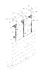
[0057] Figure 1 is an isometric partial cutaway view of a partially insulated
and partially clad wall assembly showing plural spacedly arrayed
thermally isolated Tek-brackets mounted to the structure wall
supporting vertical rails spaced apart from the structure wall and
maintaining inflammable mineral wool insulation adjacent the
structure wall and exterior cladding mounted to the vertical rails.
21
CA 02820970 2013-07-11
[0058] Figure 2 is an exploded isometric top, front and side view of a Tek-
.
bracket, a bracket isolator, a cap isolator, a button and a threaded
fastener with washer showing how the components interconnect.
[0059] Figure 3 is an isometric top, front and side view, similar to that of
Figure 2, showing the Tek-bracket assembled.
[0060] Figure 4 is an orthographic cross section side view of a Tek-bracket
mounted to a wall and showing the thermal isolation of the
components.
[0061] Figure 5 is an orthographic cross section view, similar to that of
Figure 4, showing the Tek-brackets supporting a vertical rail spaced
apart from the structure wall and exterior cladding fastened to the
vertical rail.
[0062] Figure 6 is an orthographic cross section side view, similar to that of
Figure 4, of a Tek-bracket mounted to a wall showing a vertical rail
interconnected with the Tek-bracket.
[0063] Figure 7 is an orthographic cross section top, downward looking
view, of the Tek-bracket of Figure 6.
22
CA 02820970 2013-07-11
[0064] Figure 8 is an isometric partial cutaway view of a wall assembly,
similar to that of Figure 1, showing lap siding supports carried on
horizontal rails to support exterior lap board type cladding.
[0065] Figure 9 is an orthographic cross section side view of the Tek-
brackets supporting the lap siding supports of Figure 8.
[0066] Figure 10 is an orthographic top, downward looking view, of the wall
assembly of Figure 8.
[0067] Figure 11 is an orthographic top, downward looking view of a wall
assembly similar to that of Figure 5, less the vertical rail and
showing exterior cladding fastened directly to the Tek-brackets.
[0068] Figure 12 is an isometric partial cutaway view of an exterior corner
of a structure showing horizontal rails supporting brick tile covered
wall panels, wall panels, and corner elements.
[0069] Figure 13 is an orthographic front view of a wall panel less exterior
cladding.
[0070] Figure 14 is an orthographic top edge view of the wall panel of
Figure 13.
23
CA 02820970 2013-07-11
[0071] Figure 15 is an orthographic end view of the wall panel of Figure 13.
[0072] Figure 16 is an orthographic front view of a wall panel clad with
brick-like tiles.
[0073] Figure 17 is an orthographic front view of a wall panel covered with
stucco-type masonry.
[0074] Figure 18 is an orthographic front view of a wall panel covered with
large tiles.
[0075] Figure 19 is an orthographic front view of a wall panel covered with
stone.
[0076] Figure 20 is an orthographic front view of a wall panel covered with
metal.
[0077] Figure 21 is an isometric front, top and first side view of a corner
element carrying corner brick tile cladding elements.
[0078] Figure 22 is an isometric front, top and second side view of the
corner element of Figure 21.
24
V. DETAILED DESCRIPTION OF THE PREFERRED EMBODIMENTS
Introductory Notes
100791 The readers of this document should understand that the embodiments
described
herein may rely on terminology used in any section of this document and other
terms readily apparent from the drawings and the language common therefore as
may be known in a particular art and such as known or indicated or provided by
dictionaries. Widely known and used in the preparation hereof are Webster's
Third New International Dictionary (C) 1993), The Oxford English Dictionary
(Second Edition, 1989), The New Century Dictionary ( 2001-2005) and the
American Heritage Dictionary of the English Language (4th Edition 2000) for
interpretation of terms used herein and to more adequately or aptly describe
various features, aspects and concepts shown or otherwise described herein
using
words having meanings applicable to such features, aspects and concepts.
CA 2820970 2019-12-27
[0080] This document is premised upon using one or more terms for features
shown in
one embodiment that may also apply to or be combined with other embodiments
for similar structures, functions, features and aspects of the invention.
Wording
used in the claims is also descriptive of the invention.
[0081] The readers of this document should further understand that the
embodiments
described herein may rely on terminology and features used in any section or
embodiment shown in this document and other terms readily apparent from the
drawings and language common or proper therefore.
[0082] As used herein, the term "outer", its derivatives and grammatical
equivalents
refers to that portion of our improved modular system that is proximate an
exterior of a structure. The term "inner", its derivatives and grammatical
equivalents refers to that portion of our modular system that is proximate an
interior of the structure. The
26
CA 2820970 2019-12-27
CA 02820970 2013-07-11
term "lower", its derivatives and grammatical equivalents refers to
that portion of our modular system that is vertically proximate a
foundation of the structure. The term "upper" its derivatives and
grammatical equivalents refers to that portion of our modular
system that is vertically distal from the foundation of the structure.
[0083] Our improved modular system for continuously insulating exterior
walls of a structure and securing exterior cladding to the structure
generally provides Tek-brackets 70, bracket isolators 30, cap
isolators 50, vertical rails 120, horizontal rails 140, insulation 20
and exterior cladding 16.
[0084] As shown in Figure 1, a wall assembly 10 is commonly formed of
plural spaced apart vertical wall studs 14 that communicate between
a wall plate 12 at a lower end portion and a ceiling plate (not shown)
at a upper end portion 14b. The studs 14 may be formed of a
variety of materials including but not limited to steel, aluminum,
wood, plastic and composite and are rigidly interconnected to the
wall plate 12 and to the ceiling plate (not shown) by known means.
27
CA 02820970 2013-07-11
The wall plate 12 may communicate with a structure foundation (not
shown) which provides vertical support for the wall assembly 10, or
the wall plate 12 may be supported by a floor portion (not shown)
when the structure has more than one level. Adjoining walls (not
shown) are typically formed by the same methods and with the same
materials and communicate with first wall 10 at adjacent edge
portions forming corners (Figure 12) which may form any of a variety
of angles. Window openings (not shown) and door openings (not
shown) may be defined in the wall assembly 10 by adjusting
placement of the wall studs 14 and by installing sills (not shown)
communicating between the wall studs 14.
[0085] Each wall stud 14 has an interior facing edge portion 1 4d and an
opposing exterior facing edge portion 1 4e. Utility holes (not shown)
may be formed in each wall stud 14 for passage of conduit (not
shown) and the like therethrough. Utility boxes (not shown) for light
switches, electrical outlets and the like may be spacedly arrayed
about the wall studs 14.
28
CA 02820970 2013-07-11
[0086] Depending upon the construction technique being used, and the
engineering and architectural design for the wall assembly 10,
sheathing 21 such as plywood, oriented strand board (OSB), or the
like may be attached to the exterior facing edge portions 14e of the
wall studs 14 prior to installation of a weather resistant barrier (not
shown) and prior to installation of insulation 20.
[0087] The insulation 20 is thermally resistant, is nonflammable and is non-
combustible and in the preferred embodiment is formed of mineral
wool, examples of which include, but are not limited to, mineral
fiber, rock wool, stone wool and slag wool, some of which are made
by the ThermafiberTm Company of Wabash, IN, and the RoxulTM
Company of Milton, Ontario, Canada.
[0088] Mineral wool is a known furnace product of molten rock that is
formed at a temperature of approximately 1600 C through which a
stream of pressurized air or steam is blown creating a mass of fine,
intertwined fibers with a diameter of approximately 6 to 10 pm.
Production techniques involve spinning molten rock on high-speed
29
CA 02820970 2013-07-11
spinning wheels somewhat like the process used to prepare "cotton
=
candy". Mineral wool may also contain a binder, often food grade
starch, and oil to reduce dusting.
[0089] The mineral wool insulation 20 provides a thermal barrier that
inhibits thermal conductivity and provides additional protection from
moisture penetration to reduce condensation and moisture problems
within the wall 10 assembly. Mineral wool is also widely recognized
for its sound absorbing capabilities.
[0090] Thickness (interior surface to exterior surface) of the insulation 20
may be varied to adjust for the type of Tek-bracket 70 used, for the
desired thermal resistance, sound absorbance and resistance to
moisture penetration. Common thicknesses are 2", 4", 6", 8" and
10." The mineral wool insulation 20 is generally manufactured in
rolls or sheets having a common width of 16", 18", and 24" inches,
that corresponds with common center-to-center spacing of wall
studs 14 in a wall assembly 10. Although mineral wool is preferred,
it is contemplated that other products, having similar characteristics
CA 02820970 2013-07-11
of fire resistance, sound absorbance, resistance to thermal
conductivity, ease of cutting, flame resistance, resistance to
moisture penetration, and the like may similarly be used.
[0091] Tek-bracket 70, (Figures 2-5), has a base 71, a spacing arm 81 and
a tip portion 89 opposite the base 71. The base 71 is rectilinear and
planar and has a front portion 72, a rear portion 73, a top portion
74, a bottom portion 75, a first lateral side 76, a second lateral side
77 at a bend 83 and defines fastener holes 78 therein. The spacing
arm 81 has a base end portion 82 which structurally interconnects
with the base 71 at bend 83, a tip end portion 84, a top edge 85 and
a bottom edge 86. The spacing arm 81 tapers inwardly from the
base end portion 82 toward the tip end portion 84 providing a
generally triangular configuration. (Figures 2, 3). The tip 89 has a
front end portion 90, a rear end portion 91 a top portion 92, a
bottom portion 93, a first upper wing 94 structurally interconnected
with the top portion 92 at bend 95 and a second lower wing 97
structurally interconnected with the bottom portion 93 at bend 98.
31
CA 02820970 2013-07-11
Plural spacedly arrayed fastener holes 100 are defined in the tip 89,
the first upper wing 94 and the second lower wing 97. The first
upper wing 94 and the second lower wing 97 extend laterally
generally perpendicular to the tip 89 and opposite the base 71.
[0092] The inward taper of the spacing arm 81 minimizes thermal
conductivity from the base end portion 82 to the tip end portion 84
by reducing surface area. The bends 83, 95 and 98 are preferably
900 right angles, and the Tek-bracket 70 preferably has a uniform
thickness of approximately 0.068" throughout and in the preferred
embodiment is formed of 14 gauge steel, chemically treated A792 SS
Gr. 50 Class 2 Galvalume x 48" AZ55.
[0093] The bracket isolator 30 (Figure 2) is preferably formed of
polyoxymethylene F3001, having a commercial name of CelconR
acetal copolymer M-90 GP manufactured by Celanese -Ticonia LTD
of Irvine Texas. This material is preferred because of its thermally
insulative characteristics and its durability. The bracket isolator 30
is generally rectilinear in peripheral configuration having a front side
32
CA 02820970 2013-07-11
31, a rear side (not shown), a top portion 33, a bottom portion 34, a
first lateral side 35, a second lateral side 36 and has plural spacedly
arrayed interior webs 38 with plural spaces 39 defined between the
interior webs 38. Horizontally elongated fastener holes 40 are
defined within the bracket isolator 30 by the interior webs 38. Edge
lip 42 on the front side 31 at the top portion 33 and at the bottom
portion 34 extends forwardly from the front-side 31 and are
configured to frictionally engage with the top and bottom portions
74, 75 respectively of the base 71 of the Tek-bracket 70. The side-
to-side, and top-to-bottom dimensions of the bracket isolator 30
correspond with the dimensions of the base 71 of the Tek-bracket
70 so that the fastener holes 78 defined in the base 71 align with
the fastener holes 40 defined in the bracket isolator 30.
[0094] Cap isolator 50, is also formed of polyoxymethylene and is
releasably carried on the tip 89 of the Tek-bracket 70 and extends
thereover and thereabout. The cap isolator 50 is somewhat cubic in
shape and has a front portion 51, a rear portion 52, top portion 53,
33
CA 02820970 2013-07-11
a bottom portion 54, a first lateral side portion 55, second lateral
side portion 56 and defines a bracket cavity (not shown) in which the
tip 89 of the Tek-bracket 70 is carried. Fastener slots 58 are
defined in the top portion 53, bottom portion 54, first lateral side
portion 55 and second lateral side portion 56 and communicate with
the rear portion 52 but not the front portion 51. The fastener slots
58 align with the plural spacedly arrayed fastener holes 100 defined
in the tip 89, the first upper wing 94 and the second lower wing 97.
The cap isolator 50 thermally isolates the Tek-bracket 70 from any
element carried by the Tek-brackets 70 such as, but not limited to,
vertical rail 120 and horizontal rail 140.
[0095] Button 110 (Figure 2) has the general configuration of a "washer"
having an outer circumferential edge 111 and defines a central
fastener hole 112. A shoulder (not shown) carried on one side of the
button 110 has a diameter slightly smaller than diameter of the
fastener hole 78 defined in the base 71 of the Tek-brackets 70 so
that the shoulder (not shown) fits within the fastener hole 78
34
CA 02820970 2013-07-11
providing a secure and stable interconnection therebetween which
prevents the button 110 from moving radially relative to the Tek-
bracket 70 which might allow metal to metal contact between the
Tek-bracket 70 and a fastener 15 securing the Tek-bracket 70 to
the wall assembly 10.
[0096] Vertical rail 120 (Figure 1) and horizontal rail 140 (Figure 8) are
similar in configuration and are each elongate with a first end
portion 121, 141 and a second end portion 122, 142. The rails 120,
140 have a cross-sectional configuration of a "U" having front
portion 123, 143 a first lateral side portion 125, 145 a second
lateral side portion 126, 146 and define a channel 127, 187
therebetween. As shown in Figure 1 0, the first lateral side portion
145 and the second lateral side portion (not shown) define a plurality
of spacedly arrayed fastener holes 128, 129 as well as plural
spacedly arrayed ventilation holes 131. Because the vertical rail 120
and the horizontal rail 140 are similar in configuration, the rails 120,
140 are interchangeable for interconnection with the Tek-brackets
CA 02820970 2013-07-11
70 and may be mounted vertically (Figure 1) as well as horizontally
(Figure 8).
[0097] The channel 127, 147 defined by the rails 120, 140 has height and
depth dimensions that correspond with the height and depth
dimensions of the cap isolator 50, and the fastener holes 128, 129,
which are preferably "punched" into the rails 120, 140 are spacedly
arrayed to align with the fastener slots 58 defined in the cap isolator
50 and the fastener holes 100 defined in the tip 89 and first upper
wing 94 and second lower wing 97. The rails 120, 140 are thermally
isolated from the Tek-bracket 70 by the cap isolator 50 which is
carried therebetween. A threaded fastener 62 releasably attaches
the rail 120, 140 to the Tek-brackets 70 by extending through one
of the plurality of fastener holes 128, 129 defined in the rail 120,
140, through the fastener slot 58 defined by the cap isolator 50 and
thereafter engaging with one of the spacedly arrayed fastener holes
100 defined in the tip end portion 89, first upper wing 94 and/or
second lower wing 97 of the Tek-bracket 70.
36
CA 02820970 2013-07-11
[0098] The spacing arm 81, may have a variety of lengths ranging from
approximately 2 inches to approximately 8 inches to space exterior
cladding 16 outwardly from the exterior surface of the wall assembly
10. The length of the spacing arm 81, and the specific model of
Tek-bracket 70 used, is influenced by the engineering calculations
which include the thickness of insulation 20 that is to be installed on
the structure. Mineral wool insulation 20 is commonly available in a
variety of thicknesses ranging from approximately 1 inch, to
approximately 8 inches in thickness. The configuration of the Tek-
brackets 70, and the bends 95, 98 that form the first upper wing 94
and the second lower wing 97 assist in positionally maintaining the
insulation 20 adjacent the structure exterior wall. The vertical rails
120 and the horizontal rails 140, when attached to the Tek-brackets
70 further positionally secure the insulation 20 adjacent to the
structure wall. The vertical rails 120, and the horizontal rails 140,
and more particularly the dimensions of the first lateral side 125,
145 and the second lateral side 126, 146 with the ventilation holes
37
CA 02820970 2013-07-11
131 defined therein provide a ventilation channel between an
interior facing surface of the exterior cladding 16 and the exterior
facing surface of the insulation 20 which is positionally maintained
against the wall assembly 10 by the Tek-brackets 70 and the rails
120, 140. Seams (not shown) between adjacent rolls/sheets of
insulation 20 are vertically aligned with the Tek-brackets 70 as
mounted on the wall assembly 10 to avoid any need to cut the
insulation 20 which would add labor and cost for installation of the
insulation 20 and the improved modular system.
[0100] In a further embodiment, as shown in Figure 8, lap siding supports 160
may be releasably fastened to horizontal rails 140 supported by the
Tek brackets 70 attached to the wall assembly 10. Each lap siding
support 160 has an upper end portion 161, a lower end portion 162,
an exterior facing surface 163, an interior facing surface 164, a first
lateral side 165, a second lateral side 166, a thickness 168 at the
upper end portion 161, and a thickness 169 at the lower end portion
162. Spacedly arrayed and an aligned fastener holes 167 are defined
38
CA 02820970 2013-07-11
in the exterior facing surface 163 and the interior facing surface 164
so that fasteners (not shown) may extend therethrough to secure the
lap siding supports 162 the horizontal rails 140. The thickness 168 at
the upper end portion 161 is less than the thickness 169 at the lower
end portion 162 so that exterior cladding 16 secured to the lap siding
supports 160 flares outwardly (toward the exterior) at the lower end
portions thereof forming the aesthetical appeal of lap siding. The
fasteners (not shown) that attach the lap siding supports 160 to the
rails 140 are preferably self-tapping fasteners to avoid the need to
pre-drill holes which further reduces time and expense of installation.
[0101] In the preferred embodiment, exterior cladding 16, is fastened directly
to the front portion 123 of the vertical rail 120 or front portion 143 of
the horizontal rail 140 with self tapping fasteners (not shown)
extending through the exterior cladding 16 and engaging with the
vertical rail 120 or horizontal rail 140. Other types of exterior
cladding, including but not limited to wood panels, composite panels,
siding, OSB and metallic panels may also be attached directly to the
39
CA 02820970 2013-07-11
front portion 123 of the vertical rails 120 and front portion 143
horizontal rails 140 to provide exterior cladding 16 for the structure
outward of the continuous insulation thereunder.
[0102] In a second embodiment, wall panels 180 may be releasably attached
to the vertical rails 120 and horizontal rails 140 to provide a light-
weight panelized type exterior cladding 16 for the structure.
[0103] As shown in Figures 13-15, each wall panel 180 is rectilinear and has a
front outer side portion 181, a rear inner side portion 182, a bottom
edge 183, a top edge 184 defining an offset edge portion 184a
extending the length thereof, a first lateral edge 185 defining an offset
edge portion 185a extending the length thereof and an opposing
second lateral edge 18. The first lateral edge 185, and the offset edge
portion 185a thereof, and second lateral edge 186 extend between the
top edge 184 and the bottom edge 183 and are perpendicular thereto.
[0104] A plurality of spacedly arrayed cutouts 187, which may have a
rearwardly and downwardly angled flange 188 proximate the top edge
184 are defined in each wall panel 180. Each flange 188 is offset
CA 02820970 2013-07-11
toward the rear inner side portion 182 as best shown in Figure 15. The
cutouts 187 reduce the weight of the panel 180. A plurality of grout
tangs 189 are defined in the wall panel 180 and are spacedly arrayed
about the cutouts 187 to increase frictional communication with grout
(not shown) to increase bonding with a desired facing element. The
grout tangs 189 may be offset toward the front side outer portion 181
as shown in Figure 15.
[0105] Offset edge portions 184a, 185a overlap adjacent edge portions 183,
186 of adjacent wall panels 180 to provide strength and rigidity at the
interconnections therebetween without causing a "Z-axis" offset that
might disrupt the planar wall and create an aesthetical unappealing
appearance.
[0106] Various forms and types of facing elements may be secured to the
front outer side portion 181 of each wall panel 180, and such facing
elements may include, but not be limited to, brick-like tiles 222 (Figure
16), masonry panels 221, (Figure 17), large tiles 233 (Figure 18), sheet
metal 223 such as but not limited to copper (Figure 20), stone 220
41
CA 02820970 2013-07-11
(Figure 19) composite (not shown) and the like. Because such facing
elements are supported by the wall panels 180, the front to back
thickness of the facing elements need not be great because the
support for such facing elements is the wall panel 180, the rails 120,
140 and the Tek-brackets 70.
[0107] As shown in Figures 21 and 22, corner element 270 has a backing
frame 281 with a first leg 271, a second leg 272, a top edge 273 and a
bottom edge (not shown). Offset edge portion 271a extends along the
length of the first leg 271 opposite the second leg 272 from the top
edge 273 to the bottom edge (not shown) and facilitates joining of
corner element 270 with a rail 120, 140 while preserving a flexible
interconnection with an adjacent wall panel 180. Grout tangs 189 are
spacedly arrayed about the corner element 270 to provide additional
frictional engagement with grout (not shown). Corner element 270
may be covered with brick-like tiles 283 or other coverings that are "L"
shaped (in a plan view) so that the tiles 283 extend around corner 274.
When brick-like tiles 283 are used, it is desirable that first leg 283a be
42
CA 02820970 2013-07-11
shorter than second leg 283b to visually represent the thickness of a
brick and to prevent a straight vertical line proximate the corner 274
which would provide unappealing visual evidence to an observer that
the structure is covered in a cladding system. Grout (not shown), is
used to fill gaps between the brick-like tiles 283 and to fill gaps
between adjacent wall panels 180 and adjacent corner elements 270.
[0108] Fastener holes 275 are defined in the offset edge 271 a of the corner
element 270 to carry fasteners (not shown) that extend therethrough
and threadably engage with vertical rails 120 or horizontal rails 140.
[0109] There is no structural interconnection between corner elements 270
and spacedly adjacent wall panels 180. Instead, wall panels 180 and
corner elements 270 are independently fastened to the vertical rails
120 or to the horizontal rails 140. The absence of a direct mechanical
interconnection between the corner elements 270 and the wall panels
180 allow spaces between the brick-like tiles 222 of the corner
element 270 and of the adjacent wall panels 180 to be filled with a
flexibly resilient grout that is preferably impregnated with chips of
43
CA 02820970 2013-07-11
mineral or metal so that the grout (not shown) has a visual appearance
of mortar-type grout. In the preferred embodiment the grout (not
shown) is silicone based and is flexibly resilient which allows for
thermal expansion and contraction that might occur and prevents the
formation of cracks that might otherwise develop if mortar-type grout
is used. Further, the absence of mechanical interconnection between
the wall panels 180, and the corner elements 270 provides a flexing
joint in the wall cladding system that can accommodate movements,
vibrations, expansions and contractions caused by forces such as, but
not limited to, wind, seismic activity, thermal expansion and building
shrinkage. Finally, the absence of mechanical interconnection of the
wall panels 180 and the corner elements 270 provides some amount of
flexibility in the installation of the cladding system to adjust for
inaccuracies, warps, bulges and the like that make wall assemblies 10
less than perfectly planar and corners less than perfect right angles.
[0110] The edge lips provide a means for the bracket isolator 30 to be
attached to the Tek-brackets 70 at the fabricator which eliminates the
44
CA 02820970 2013-07-11
need for an installer to handle and align each Tek-bracket 70 with the
isolator 30 during installation of the wall system which promotes
efficiency.
[0111] The plurality of fastener holes 100 defined in the tip 89 and first and
second wings 94, 97 respectively as well as the elongated fastener
slots 58 defined in the cap isolator 50 provide a means for "plumbing"
the wall cladding system to vertical planar as necessary, by moving the
rail 120, 140 closer to the wall assembly 10 or further away from the
wall assembly 10 as necessary to change the angle of the rail 120, 140
relative to the wall assembly 10.
[0112] Front portion 123 of the vertical rail 120 and front portion 143 of the
horizontal rail 140 provide a mounting surface for the exterior
cladding 16. The first and second wings 94, 97 respectively, retain and
positionally maintain insulation 20 adjacent the exterior surface of the
wall assembly 10 and spaced apart from the exterior cladding 16 to
maintain a rain screen 22 between the insulation 16 and the interior
surface of the exterior cladding 16. Insulation clips (not shown) may
CA 02820970 2013-07-11
also be attached to the inward portions of the vertical rails 120 or
horizontal rail 140 to positionally maintain the insulation 20, spaced
apart from inside surface of the exterior cladding 16 and the rear inner
side 182 of the wall panels 180. The insulation 20 has the tendency to
move toward the exterior cladding 16 due to gravity loads and wind
loads that cause pressure reductions within the wall assembly 10.
Space 22 between the outward most portion of the insulation 16 and
the inner most surface of the exterior cladding 16 is known, in the
industry, as a "rain screen" that prevents moisture from passing from
the exterior of the structure wall to the insulation 16 and allows
condensation to occur and dry within the wall assembly 10 without
detrimentally affecting the wall assembly 10 and insulation 126.
[0113] Our improved modular system provides a means for adding insulation
20 to the exterior of a structure, it provides a means for mounting
exterior cladding 16 on a structure and it provides a means to "plumb"
a wall assembly 10 to vertical and flatness.
46
CA 02820970 2013-07-11
[0114] Mounting exterior cladding 16 on an existing structure, or refurbishing
and adding insulation to the exterior of an existing structure is more
economical using our improved system because of the additional
adjustability features provided by the plurality of spacedly arrayed
fastener holes 100 defined in the Tek-bracket 70.
[0115] Having described the structure of our improved modular system its
operation may be understood.
[0116] A wall panel 180 is clad on its first front side portion 181 with a
desired cladding element, such as brick-like tile 222. The desired
cladding element is secured to the wall panel 180 with adhesive. If
brick-like tiles 222 are used it is necessary to bend the grout tangs
189 forwardly prior to installation of grout so that grout tangs 189
extend into the grout filling spaces between the brick-like tiles 222.
[0117] The desired cladding elements are also applied to the first and second
legs 271, 272 respectively of the corner elements 270 and secured
thereto with known adhesive. If brick corner tiles 283 are fastened to
the corner elements 270, the first leg 283a and second leg 283b are
47
CA 02820970 2013-07-11
alternated so that first and second legs 283a, 283b respectively
alternate on the first leg 271 and second leg 272 of the corner element
270.
[0118] The Tek-bracket 70 and bracket isolators 30 are preferably
interconnected with one another at the time of manufacture to increase
efficiency and to reduce installation time with the base 71 of the Tek-
bracket 70 positionally secured to the front side 31 of the bracket
isolator 30 with the edge lips 42 engaging with the top portion 74 and
bottom portion 75 of the base 71 of the Tek-bracket 70. Similarly the
cap isolators 50 are preferably interconnected with the Tek-bracket 70
tip portions 89 at the manufacturer and the buttons 110 are attached
to the base 71 about the fastener holes 78.
[0119] The Tek-brackets 70 and bracket isolators are secured to a structure
exterior wall 13 with the Tek-brackets 70 vertically aligned so that the
fastener holes 78 defined in the base portions 71 are aligned with the
wall studs 14 or other structural elements (not shown) of the wall
assembly 10. It is imperative that the Tek-brackets 70 be vertically
48
CA 02820970 2013-07-11
aligned and horizontally aligned so as to engage with and support the
vertical rails 120 or horizontal rails 140.
[0120] Fasteners 15 are extended through the fastener hole 112 defined in
the button 110 and through the fastener holes 78 to pass there-
through and to pass through the fastener holes 40 defined in the
bracket isolator 30. The fastener 15 thereafter penetrates the wall
assembly 10 and engages with a wall stud 14 or other structural
element (not shown).
[0121] The number of Tek-brackets 70 installed on the structure to support
the exterior cladding 16 is dependent upon the engineering
calculations that take into account the weight of the cladding 16,
predicted wind loads, traffic vibration, and the like. Because the Tek-
bracket 70 interrupt the insulation 20 and affect the performance of
the insulation 20 it is preferable to use the minimum number of Tek-
brackets 70 that will safely meet required engineering load calculations
and safety tolerance.
49
CA 02820970 2013-07-11
[0122] The process of installing Tek-brackets 70 is continued so that the Tek-
.
brackets 70 are spacedly arrayed and extend from the lowest desired
level, to the upper-most desired level of the structure and are spacedly
arrayed on the wall assembly 10 in a configuration that will support the
rails 120, 140.
[0123] After the Tek-brackets 70 have been secured to the exterior wall 13 of
the structure, the vertical rails 120 or horizontal rails 140, whichever is
to be used to support the exterior cladding 16 are positioned so that
the channels 127, 147 defined by the rails 120, 140 respectively fit
over and about the cap isolators 50 carried on the tip ends 89 of the
Tek-brackets 70. The fastener holes 128, 129 defined in the rails 120,
140 are aligned with the fastener holes 100 defined in the tip 89 and
wings 94, 97 of the Tek-bracket 70 and the fastener slots 58 of the
cap isolator and fasteners 62 are engaged therewith.
[0124] Because the rail 120, 140 is thermally isolated from the Tek-bracket 70
by the cap isolator 50, the only metal to metal contact is the fastener
62 securing the rail 120, 140 to the Tek-bracket 70. This minimal
CA 02820970 2013-07-11
metal to metal contact greatly reduces thermal transfer from the rail
120, 140 to the Tek-bracket 70 and visa-versa.
[0125] Similar fasteners 62 are inserted through the remaining fastener holes
128, 129 defined in the rails 120, 140, through the fastener slots 58 in
the cap isolators 50 and into the fastener holes 100 defined in the
Tek-bracket 70 securing the rails 120, 140 to the Tek-brackets 70.
[0126] Before the fasteners 62 interconnecting the rails 120, 140 and Tek-
brackets 70 are tightened, adjustments should be made to ensure that
the vertical rails 120 are vertical, and the horizontal rails 140 are not
bowed inwardly or outwardly resulting from non-planer wall
assemblies 10. The adjustment is made by adjusting the position of
the rails 120, 140 relative to the Tek-bracket 70 by moving the rail
120, 140 more proximate to, or more distal from the exterior wall 13
of the structure which responsively changes the angle of the rail 120,
140 relative to the wall 13.
[0127] Mineral wool insulation 20 is installed adjacent the exterior wall 13
to
extend completely between the spaced apart Tek-brackets 70. The
51
CA 02820970 2013-07-11
wings 94, 97 of the Tek-brackets 70 as well as the rails 120, 140
retain and positionally maintain the insulation 20 against the exterior
wall 13 and prevent the insulation 20 from expanding or moving
outwardly into direct contact with the interior surface of the wall
cladding 16, or wall panels 180 and maintain the rain screen 22.
Thereafter, the exterior cladding 16 may be fastened directly to the
front side portions 123, 143 of the rails 120, 140 with fasteners
extending therethrough, or lap siding supports 160 may be attached to
the front side portion 143 of the horizontal rails 140 and thereafter lap
siding may be attached to the structure, similar to the process
described above.
[0128] If exterior cladding 16 such as lap board, or metal sheeting, is to be
fastened directly to the front portion 123, 143 of the vertical rails 120
or horizontal rails 140 the exterior cladding 16 may be placed directly
against the front portion 123, 143 and self tapping fasteners (not
shown) are used to attach the exterior cladding 16 by passing the
52
CA 02820970 2013-07-11
fasteners through the exterior cladding 16 and engaging the vertical
rail 120 or horizontal rail 140.
[0129] If wall panels 180 and corner elements 270 are to be used to clad the
structure, vertical rails 120 or horizontal rails 140 are secured to the
Tek-brackets 70 with fasteners 62 extending through the fastener
holes 128, 129 and engaging with the fastener holes 100 defined in
the tip 89 and/or wings 94, 97 of the Tek-bracket 70.
[0130] The vertical and horizontal spacing of the vertical rails 120, and
horizontal rails 140 is dependent upon the spacing of the Tek-brackets
70 and is preferably the same as or an evenly spaced portion of the
height and width dimensions of the wall panel 180, so that a single
wall panel 180 engages with plural rails 120, 140.
[0131] Corner elements 270 are installed at the structure corners with
fasteners (not shown) extending through fasteners holes 275 defined
in the offset edge portion 271a of the corner elements 270. In the
preferred embodiment, the fasteners (not shown) engage with the front
surface 123, 143 of the rails 120, 140 and plural corner elements 270
53
CA 02820970 2013-07-11
"
are installed on the structure corner in vertical alignment extending
from the lowest desired level to highest desired level.
[0132] The previously prepared wall panels 180 are positioned adjacent to the
wall assemblyl 0, and are lifted into position and placed in direct
frictional contact with the front portions 123, 143 of the rails 120, 140
so that the front portions 123, 143 rails 120, 140 frictionally engage
with the second rear side portion 182 of the wall panel 180. Thereafter
self tapping fasteners (not shown) are passed through the uncovered
edge portions of the wall panel 180 to engage with and positionally
secure the wall panel 180 to the rails 120, 140. Thereafter, additional
wall panels 180 are positioned against the rails 120, 140 and are
positionally manipulated so that adjacent edge portions 185, 186 of
adjacent wall panels 180 abut. Self tapping fasteners (not shown) are
used to positionally secure the wall panels 180 to the rails 120, 140.
[01331 In locations where the desired exterior cladding 16 has not been
previously secured to the wall panels 180, such as the alternating brick
tile positions that extend across adjoining edges of adjacent wall
54
CA 02820970 2013-07-11
panels 180, brick tiles 222 are added to those locations. Grout is
added to the spaces between the brick tiles 222 to complete the
appearance of brick construction.
[0134] Silicone based grout having a color similar to that of mortar based
grout is impregnated with minerals or metallic chips having a desired
color. The mineral or metallic chips provide the silicone grout with the
appearance and texture of mortar based grout, but retains resiliency
and flexibility, and is resistant to formation of cracks and gaps.
Silicone based grout is also used to fill the spaces between the edges
of the wall panels 180 and the adjacent edges of the brick corner tiles
283 covering the corner elements 270.
[0135] Having thusly described our invention, what we desire to protect by
Utility Letters Patent and
[0136] What we claim is: