Note : Les descriptions sont présentées dans la langue officielle dans laquelle elles ont été soumises.
CA 02821180 2013-07-11
DIRECT DRIVE ROTATION DEVICE FOR PASSIVELY MOVING FLUID
BACKGROUND
Technical Field:
The present application relates to a direct drive rotation device configured
for
passively moving fluid.
Description of Related Art:
Conventionally, fluid pumps can be used to move lubrication/cooling fluid
within a
gearbox, transmission, or other mechanical system that may require
lubrication/cooling. A conventional gearbox fluid pump is configured to draw
fluid
from a sump and pump the fluid against gravitational forces to a desired
location.
Conventional fluid pumps have significant disadvantages, such as: many
vulnerabilities to operational failure (including fluid transfer lines),
increased
certification requirements (in an aircraft implementation), expense,
complexity, and
maintenance requirements, to name a few.
Hence, there is a need for an improved device for moving fluid against the
forces of
gravity.
SUMMARY
In one aspect, there is provided a device for moving a fluid within a gearbox,
the
device comprising: a base portion coupled to a rotatable member within the
gearbox;
a conical portion having a plurality of ear members, each ear member being
configured to capture a fluid during a rotation of the device; wherein the
device is
configured to utilize a centrifugal force for moving the fluid captured by
each ear
member along an interior surface of the conical portion toward the base
portion.
Page 1
CA 02821180 2013-07-11
In another aspect, there is provided a device for moving a fluid within a
gearbox, the
device comprising: a base portion coupled to a rotatable member within the
gearbox;
a conical portion having an external threaded portion configured to capture a
fluid
during a rotation of the device; wherein the threaded portion is configured to
utilize a
centrifugal force for moving the fluid captured by the threaded portion along
a
exterior surface of the conical portion toward the base portion.
In a further aspect, there is provided a device for moving a fluid within a
gearbox, the
device comprising: a screw member coupled to a rotatable member within the
gearbox; a casing having an inlet that is submerged in a fluid reservoir;
wherein
rotation of the rotatable member causes the screw member to rotate, thereby
causing a fluid to be drawn into the inlet.
DESCRIPTION OF THE DRAWINGS
The novel features believed characteristic of the apparatus of the present
application
are set forth in the appended claims. However, the apparatus itself, as well
as a
preferred mode of use, and further objectives and advantages thereof, will
best be
understood by reference to the following detailed description when read in
conjunction with the accompanying drawings, wherein:
Figure 1 is a side view of an aircraft having a gearbox, according to one
example
embodiment;
Figure 2 is a perspective view of the gearbox, according to one example
embodiment;
Figure 3 is a sectional view, taken at section lines 3-3, of a device in the
gearbox,
according to one example embodiment;
Figure 4 is a detail view of a portion of the device from Figure 3, according
to one
example embodiment;
Figure 5 is an alternative embodiment detail view of a portion of the device,
according to one example embodiment;
Page 2
CA 02821180 2013-07-11
Figure 6 is an alternative embodiment detail view of a portion of the device,
according to one example embodiment;
Figure 7 is a sectional view, taken at section lines 7-7, of a device in the
gearbox,
according to one example embodiment;
Figure 8 is a sectional view, taken at section lines 8-8, of a device in the
gearbox,
according to one example embodiment;
Figure 9 is a sectional view, taken at section lines 9-9, of a device in the
gearbox,
according to one example embodiment;
Figure 10 is a detail view of a portion of the device from Figure 9, according
to one
example embodiment;
Figure 11 is a detail view of a portion of the device from Figure 9, according
to one
example embodiment; and
Figure 12 is a sectional view, taken at section lines 12-12, of a device in
the
gearbox, according to one example embodiment.
Page 3
CA 02821180 2013-07-11
DESCRIPTION OF THE PREFERRED EMBODIMENT
Illustrative embodiments of the apparatus are described below. In the interest
of
clarity, all features of an actual implementation may not be described in this
specification. It will of course be appreciated that in the development of any
such
actual embodiment, numerous implementation-specific decisions must be made to
achieve the developer's specific goals, such as compliance with system-related
and
business-related constraints, which will vary from one implementation to
another.
Moreover, it will be appreciated that such a development effort might be
complex
and time-consuming but would nevertheless be a routine undertaking for those
of
ordinary skill in the art having the benefit of this disclosure.
In the specification, reference may be made to the spatial relationships
between
various components and to the spatial orientation of various aspects of
components
as the devices are depicted in the attached drawings. However, as will be
recognized by those skilled in the art after a complete reading of the present
application, the devices, members, apparatuses, etc. described herein may be
positioned in any desired orientation. Thus, the use of terms such as "above,"
"below," "upper," "lower," or other like terms to describe a spatial
relationship
between various components or to describe the spatial orientation of aspects
of such
components should be understood to describe a relative relationship between
the
components or a spatial orientation of aspects of such components,
respectively, as
the device described herein may be oriented in any desired direction.
The apparatus of the present application is a direct drive rotation device
configured
for passively moving fluid. More specifically, the direct drive rotation
device is
configured to passively move lubrication/cooling fluid within a gearbox, or
other
mechanical system that utilizes lubrication/cooling fluid. The apparatus is
capable of
efficiently moving fluid against gravity to desired locations within a
gearbox. Further,
the apparatus is configured to be direct drive and passively move fluid,
thereby
precluding certification requirements that may be necessitated by using a
conventional pump to move fluid within a gearbox. The apparatus is also
configured
Page 4
CA 02821180 2013-07-11
to accurately and effectively move fluid to desired locations within a
gearbox.
Further, some embodiments of the apparatus have the ability to catch ambient
fluid
and redistribute to desired locations within a gearbox. These and other
advantages
of the apparatus are further described herein. Certain embodiments of the
present
application may include some, all, or none of the above advantages. One or
more
other technical advantages may be readily apparent to those skilled in the art
from
the figures, descriptions, and claims included herein.
Referring now to Figure 1 in the drawings, a rotorcraft 101 is illustrated.
Rotorcraft
101 has a rotor system 103 with a plurality of rotor blades 105. The pitch of
each
rotor blade 105 can be managed in order to selectively control direction,
thrust, and
lift of rotorcraft 101. Rotorcraft 101 further includes a fuselage 107, anti-
torque
system 109, and an empennage 111. Torque is supplied to rotor system 103 and
anti-torque system 109 with at least one engine 113. A main rotor gearbox 115
is
operably associated with the engine main output driveshaft and the main rotor
mast.
Further, an intermediate gearbox 117 is operably associated with a tail rotor
drive
shaft 119 and a tail rotor drive shaft 121.
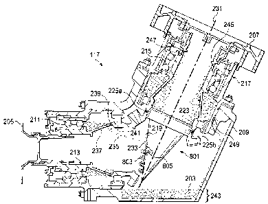
Referring now also to Figures 2-4, intermediate gearbox 117 includes a direct
drive
rotation device 201 configured to passively move a fluid 203 to desired
locations
within gearbox 117. For example, device 201 is configured to move fluid 203
against the forces of gravity. Device 201 can be categorized as direct drive
for being
coupled to a rotating portion of gearbox 117, thereby passively rotating
without
active command, or use of sequential, subsequent, fluid transfer systems
(e.g., fluid
lines), during operation of the gearbox 117.
Gearbox 117 can include an input member 205 that is coupled to tail rotor
drive shaft
119. Similarly, gearbox 117 can include an output member 207 that is coupled
to tail
rotor drive shaft 121. Gearbox 117 is configured to transition torque from
along the
axis of tail rotor drive shaft 119 to along the axis of tail rotor drive shaft
121. The
gearbox 117 includes a housing 209. An input rotating member 213 is rotatable
relative to housing 209 with an input duplex bearing 211 operably associated
Page 5
CA 02821180 2013-07-11
therebetween. Similarly, an output rotating member 217 is rotatable relative
to
housing 209 with an output duplex bearing 215 operably associated
therebetween.
During operation, it can be necessary to supply lubrication/cooling fluid 203
to
bearings, seals, and other gearbox related components. In
the illustrated
embodiment, device 201 is configured to supply lubrication/cooling fluid to
input
duplex bearing 211 and output duplex bearing 215. It should be appreciated
that the
exact configuration of device 201 is implementation specific. Further, one of
ordinary skill in art with benefit of this disclosure would recognize that
device 201
can be modified to selectively collect and supply fluid to various components
within a
gearbox.
In the illustrated embodiment, device 201 has a conical portion 219, an inlet
portion
221, and a base portion 223. It should be appreciated that even though conical
portion 219, inlet portion 221, and base portion 223 are illustrated as an
integral
device, an alternative embodiment can include the segregation of conical
portion
219, inlet portion 221, and base portion 223 into individual components
operably
associated to each other. Device 201 can be coupled to output rotating member
217
with fasteners 225a and 225b, for example. It should be appreciated that
device 201
can be coupled to output rotating member 217 in a variety of configurations
using
any variety of suitable components.
Inlet member 221 is a narrow cylindrical portion having a threaded portion 227
on
the interior of inlet member 221, the threaded portion 227 being configured to
move
fluid during rotation of device 201. In the illustrated embodiment, threaded
portion
227 includes threads machined into the interior of inlet portion 221.
Referring briefly
to Figure 5, an alternative embodiment of inlet portion 221 includes a
threaded insert
501 that is threaded into recessed grooves in threaded portion 227. Referring
briefly
to Figure 6, an alternative embodiment of inlet portion 221 includes an insert
601
having an internal auger configuration. Insert 601 can be press fit, threaded,
and/or
bonded to the interior of inlet portion 221, for example. Figures 4-6 are
illustrative of
a wide variety of possible configurations of inlet portion 221.
Page 6
CA 02821180 2013-07-11
During operation, device 201 rotates in conjunction with output rotating
member 217,
both device 201 and output rotating member 217 having a common axis of
rotation
231. The exact rotational speed of device 201 and output rotating member 217
is
implementation specific, but in one example embodiment, device 201 and output
rotating member 217 rotate at approximately 4500 revolutions per minute.
Rotation
of device 201 generates outward centrifugal forces perpendicular to axis of
rotation
231. Rotation of device 201 causes fluid 203 to be drawn from a reservoir 243
into
inlet portion 221 by the lifting of fluid 203 with threaded portion 227.
Further,
centrifugal forces motivate fluid 203 to gravitate radially outward; as such,
once fluid
203 reaches conical portion 219, the centrifugal forces cause fluid 203 to
flow in the
direction of base portion 223 due to the slope of conical portion 219.
In one example embodiment, an orifice 233 can be strategically placed in
conical
portion 219 so that a portion of fluid 203 is projected from orifice 233 to a
desired
area with gearbox 117. Orifice 233 can be selectively sized in accordance with
the
desired volume of fluid 203 to be projected. In the illustrated embodiment,
orifice
233 is sized and located so that a fluid stream 235 of fluid 203 exiting from
orifice
233 is deposited on a surface 237 of input rotating member 213 before flowing
through a port 239 and onto input duplex bearing 211. After
lubricating/cooling input
duplex bearing 211, fluid 203 can return to reservoir 243 via a passage. A dam
member 241 can be used to direct the flow of fluid through port 239. It should
be
appreciated that even though a single orifice 233 is illustrated, any
plurality of
orifices 233 having any variety of shapes and sizes can be used to selectively
deposit fluid 203 on one or more components. Further, even though the
illustrated
embodiment is described using fluid 203 to lubricate/cool bearings, device 201
is
equally adaptable to lubricate/cool other components, such as gears.
The portion of fluid 203 that bypasses orifice 233 flows along on the interior
surface
of conical portion 219 toward the location of output duplex bearing 215. In
the
illustrated embodiment, an upper portion of base member 223 acts as a dam wall
thereby allowing a volume of fluid 203 to accumulate along a recessed portion
of
output rotating member 217 before accumulating to a height that results in
fluid 203
Page 7
CA 02821180 2013-07-11
flowing into a passage 247 and onto output duplex bearing 215. A dam 245 can
be
integrated into output rotating member 217 to prevent fluid 203 from flowing
past
passage 247. Fluid 203 can return to reservoir 243 via passage 249.
Referring now also to Figure 7, an alternative embodiment device 701 is
illustrated.
Device 701 is substantially similar in form and function to device 201, except
as
noted herein. Thus, disclosure herein regarding device 201 is also applicable
to
device 701, except as noted herein. Further, device 701 can also incorporate
features of devices 801 and 901, therefore it should be appreciated that the
disclosure with regard to devices 801 and 901 is also applicable to device
701.
Device 701 is configured to capture fluid 203 from the ambient atmosphere with
a
scoop 703 in lieu of drawing fluid 203 from reservoir with inlet portion 227.
However,
an alternative embodiment of device 701 can include inlet portion 221 for
drawing
fluid 203 from the reservoir in addition to scoop 703 for collecting fluid 203
from the
ambient atmosphere. Fluid 203 drawn from the ambient atmosphere with scoop 703
can be in the form of relatively small droplets and/or large splashed
quantities, for
example. Further, a slot 705 can be used to supplement or replace scoop 703.
Scoop 703 and slot 705 can be selectively located to catch fluid 203 that is
being
splashed and/or misted by components with gearbox 117. The interior surface of
conical portion 219 can include a lip that prevents fluid that is caught by
scoop 703
to exit through slot 705.
Referring now also to Figure 8, an alternative embodiment device 801 is
illustrated.
Device 801 is substantially similar in form and function to device 201, except
as
noted herein. Thus, disclosure herein regarding device 201 is also applicable
to
device 801, except as noted herein. Further, device 801 can also incorporate
features of devices 701 and 901, therefore it should be appreciated that the
disclosure with regard to devices 701 and 901 is also applicable to device
801.
Device 801 is configured to capture fluid 203 from the ambient atmosphere with
a
plurality of ears 803 in lieu of drawing fluid 203 from reservoir with inlet
portion 227.
However, an alternative embodiment of device 801 can include inlet portion 221
for
drawing fluid 203 from the reservoir in addition to ears 803 for collecting
fluid 203
Page 8
CA 02821180 2013-07-11
from the ambient atmosphere. Fluid 203 drawn from the ambient with ears 803
can
be in the form of relatively small droplets and/or large splashed quantities,
for
example. Further, ears 803 can be selectively located to catch fluid 203 that
is being
splashed and/or misted by components with gearbox 117. Each ear 803 includes
an
orifice 805 that allows fluid 203 to migrate to the interior surface of
conical portion
219. The interior surface of conical portion 219 can be designed to guide
fluid such
that it prevents fluid that is caught by ears 803, scoop 703, or inlet portion
221 from
exiting back through a downstream ear 803.
Referring now to Figures 9-12, an alternative embodiment device 901 is
illustrated.
Device 901 is substantially similar in form and function to device 201, except
as
noted herein. Thus, disclosure herein regarding device 201 is also applicable
to
device 801, except as noted herein. Further, device 901 can also incorporate
features of devices 701 and 801, therefore it should be appreciated that the
disclosure with regard to devices 701 and 801 is also applicable to device
901.
Device 901 is configured to capture fluid 203 from the ambient atmosphere with
an
external threaded portion 903 in lieu of drawing fluid 203 from reservoir with
inlet
portion 227. However, an alternative embodiment of device 901 can include
inlet
portion 221 for drawing fluid 203 from the reservoir in addition to external
threaded
portion 903 for collecting fluid 203 from the ambient atmosphere. Fluid 203
drawn
from the ambient atmosphere with external threaded portion 903 can be in the
form
of relatively small droplets and/or large splashed quantities, for example.
Further,
external threaded portion 903 can be selectively located to catch fluid 203
that is
being splashed and/or misted by components with gearbox 117. A lip member 905
can be associated with base member 223 and/or output rotating member 217 for
catching fluid 203 from the exterior surface of conical portion 219. Further,
lip
member 905 can be configured to allow fluid to accumulate so that centrifugal
forces
motivate fluid 203 toward passage 247.
Figures 10 and 11 are expanded views of external threaded portion 903. As
shown
in Figure 11, external threaded portion 903 includes a concave portion 905 to
retain
and move fluid 203 toward base member 223 along conical portion 219. External
Page 9
CA 02821180 2013-07-11
threaded portion 903 is merely illustrative of a wide variety of possible
implementation specific configurations for capturing and moving fluid 203
along the
exterior surface of conical portion 219.
Referring now also to Figure 12, gearbox 117 can include a direct drive device
1201
configured to passively move fluid 203 to desired locations within gearbox
117.
Device 1201 is an alternative embodiment of device 201. Similar to device 201,
device 1201 is configured to move fluid 203 against the forces of gravity.
Device
1201 can be categorized as direct drive, and passive, for having a fluid
moving
member coupled to a rotating portion of gearbox 117, which thereby passively
rotates without active command, or subsequent, sequential, fluid transfer
systems
(e.g., fluid lines), during operation of the gearbox 117.
Gearbox 117 can include an input member 205 that is coupled to tail rotor
drive shaft
119. Similarly, gearbox 117 can include an output member 207 that is coupled
to tail
rotor drive shaft 121. Gearbox 117 is configured to transition torque from
along the
axis of tail rotor drive shaft 119 to along the axis of tail rotor drive shaft
121. The
gearbox 117 can include a housing 209. Input rotating member 213 is rotatable
relative to housing 209 with an input duplex bearing 211 operably associated
therebetween. Similarly, an output rotating member 217 is rotatable relative
to
housing 209 with an output duplex bearing 215 operably associated
therebetween.
During operation, it can be necessary to supply lubrication/cooling fluid 203
to
bearings, seals, and other gearbox related components. In
the illustrated
embodiment, device 1201 is configured to supply lubrication/cooling fluid to
input
duplex bearing 211 and output duplex bearing 215. It should be appreciated
that the
exact configuration of device 1201 is implementation specific. Further, one of
ordinary skill in art with benefit of this disclosure would recognize that
device 1201
can be modified to selectively supply fluid to various components within a
gearbox.
In the illustrated embodiment, device 1201 includes a screw member 1203 having
a
shaft 1205. Shaft 1205 is coupled to output member 207 such that shaft 1205 is
rotated in conjunction with output member 207 about axis of rotation 231. In
an
Page 10
CA 02821180 2013-07-11
alternative embodiment, shaft 1205 is coupled to output rotating member 217,
or
another rotating component within gearbox 117. Screw member 1203 has a
threaded portion 1207 that resides within a casing 1209. A support member 1211
can include one or bearings so as to rotatably support shaft 1205 against
casing
1209. Casing 1209 has an inlet 1213 submerged within reservoir 243.
During operation, screw member 1203 rotates in conjunction with output member
207. The exact rotational speed of screw member 1203 and output member 207 is
implementation specific, but in one example embodiment, screw member 1203 and
output member 207 rotate at approximately 4500 revolutions per minute.
Rotation of
screw member 1203 draws fluid 203 up into casing 1209 through inlet 1213 by
the
lifting of fluid 203 with threaded portion 1207. Once fluid 203 has traveled
to the
upper portion of casing 1209, centrifugal forces throw fluid 203 radially
outward onto
the inner surface of output rotating member 217. Fluid 203 can then travel
through
passage 247 and onto output duplex bearing 215. Dam 245 can be integrated into
output rotating member 217 to prevent fluid 203 from flowing past passage 247.
Fluid 203 can return to reservoir 243 via passage 249.
In one example embodiment, one or more orifices 1215 can be strategically
placed
in casing 1209 so that a portion of fluid 203 is projected from each orifice
1215 to a
desired area with gearbox 117. Orifices 1215 can be selectively sized in
accordance
with the desired volume of fluid 203 to be projected. In the illustrated
embodiment,
orifices 1215 are sized and located so that fluid streams 1217 of fluid 203
exiting
from orifices 1215 are deposited on a surface 237 of input rotating member 213
before flowing through a port 239 and onto input duplex bearing 211. In the
illustrated embodiment, the fluid velocity for projecting fluid streams 1217
is derived
from screw member 1203. After lubricating/cooling input duplex bearing 211,
fluid
203 can return to reservoir 243 via a passage. A dam member 241 can be used to
direct the flow of fluid 203 through port 239.
Page 11
CA 02821180 2013-07-11
Even though the illustrated embodiment is described using device 1201 to
lubricate/cool bearings with fluid 203, device 1201 is equally adaptable to
lubricate/cool other components, such as gears.
Devices 201, 701, 801, 901, and 1201 include one or more significant
advantages
over conventional apparatuses used to move fluid within a gearbox, such as: 1)
efficiently moving fluid against gravity to desired locations within a
gearbox; 2)
precluding certification requirements that may be necessitated by using a
conventional pump for moving fluid within a gearbox; 3) accurately moving
fluid to
desired locations within a gearbox; and 4) ability to catch ambient fluid and
redistributing to desired locations within a gearbox.
It should be appreciated that rotorcraft 101 is merely illustrative of a wide
variety of
aircraft that can implement devices 201, 701, 801, 901, and 1201 in a gearbox.
Other aircraft implementations can include fixed wing aircraft, tilt rotor
aircraft,
unmanned aircraft, gyrocopters, and spacecraft, to name a few examples.
Further,
even though devices 201, 701, 801, 901, and 1201 are particularly well suited
for an
aircraft implementation, devices 201, 701, 801, 901, and 1201 may be
implemented
on any mechanical system that may require fluid movement to one or more
components.
The particular embodiments disclosed above are illustrative only, as the
apparatus
may be modified and practiced in different but equivalent manners apparent to
those
skilled in the art having the benefit of the teachings herein. Modifications,
additions,
or omissions may be made to the apparatuses described herein without departing
from the scope of the invention. The components of the apparatus may be
integrated or separated. Moreover, the operations of the apparatus may be
performed by more, fewer, or other components.
Furthermore, no limitations are intended to the details of construction or
design
herein shown, other than as described in the claims below. It is therefore
evident
that the particular embodiments disclosed above may be altered or modified and
all
Page 12
CA 02821180 2013-07-11
such variations are considered within the scope of the application.
Accordingly, the
protection sought herein is as set forth in the claims below.
Page 13