Note : Les descriptions sont présentées dans la langue officielle dans laquelle elles ont été soumises.
CA 02821570 2013-06-13
BREWING DEVICE FOR CREATING A COFFEE BEVERAGE AND
METHOD FOR CREATING A COFFEE BEVERAGE BY MEANS OF A
BREWING DEVICE
The present invention relates to a brewing device for
creating a coffee beverage having a crema unit arranged
in a coffee outlet, with which a crema can be created.
The invention further relates to a method for creating
a coffee beverage with such a brewing device.
In particular the invention relates to a brewing device
having a specially configured crema unit by means of
which it is possible to vary the amount of crema
created per brewing operation.
A brewing device with the option to increase the amount
of crema created during the brewing operation is known,
for example, from the EP 2 168 465 Al. The brewing
device described in there is equipped with a so-called
crema valve which is arranged between the brewing unit
and the coffee outlet and which limits the outflow of
the coffee brewed in the brewing device into the coffee
outlet line by means of a compression-spring-loaded
stopper. Due to the fact that the brewed coffee is
pressed under pressure in direction of the stopper, the
compression spring - provided the brewing water
pressure is sufficiently high - exposes an annular gap
through which the brewed coffee can flow into the
output pipe. Due to the fact that this annular gap is
of limited size turbulences are created as the brewed
coffee passes through. This swirling through of the
brewed coffee causes a fine-pored foam to be created
which is called crema.
In order to be able to increase the quantity of crema
produced in this way, the conventional brewing device
comprises a gas injector with which gas at variable
CA 02821570 2013-06-13
- 2 -
pressure and in variable amounts can be introduced into
the crema chamber. Due to this additional swirling
through of the coffee within the crema chamber, i.e.
after passing through the annular gap, the amount of
crema produced in the conventional brewing device is
increased. Therefore, whilst it is possible by means of
the conventional brewing device to artificially
increase the amount of the classically produced crema
by introducing a gas into the crema chamber, no
provision is made for decreasing the amount of the
particular produced crema to a minimum.
Moreover due to the regionally very different coffee
cultures and the resulting different drinks of coffee
such as Cappuccino, Latte Macchiato, Espresso,
different personal tastes exist, wherein there is also
a desire as regards the amount and the pore size of the
crema to produce less or larger-pore crema, going as
far as coffee beverages to be output by the brewing
device, which have no crema layer whatsoever.
Due to the use of a compression-spring-loaded valve in
the conventional brewing device there is also a danger
for drink residues to accumulate in the valve so that
this compression-spring-loaded valve gets clogged up to
an extent where a smooth operation of the valve is
impaired. A compression-spring-loaded valve may under
certain circumstances resist the increased pressure of
the brewing water before it exposes the annular gap for
the passage of the brewed coffee beverage. Whilst this
may cause a change in the consistency of the crema,
such clogging up in the worst case leads to the valve
suddenly releasing under sufficiently high brewing
water pressure and explosively opening against the
restoring force of the spring. Due to the equally
sudden emergence of the coffee in the coffee spout it
may therefore happen for example that the coffee sprays
CA 02821570 2013-06-13
- 3 -
out of the spout under excessively initial pressure,
resulting in an unsatisfactory coffee beverage.
A further disadvantage of the conventional brewing
device consists in that due to the spring-loaded crema
valve during standstill of the brewing device, i.e. for
example following a completed brewing operation, any
coffee water remaining in the coffee outlet line builds
up behind the crema valve and cannot not return into
the brewing chamber. When subsequently another brewing
operation is performed this residual liquid is
initially output at the coffee outlet before the
freshly brewed coffee reaches the coffee outlet. In
case of a prolonged standstill between consecutive
brewing operations it is then possible that this
residual liquid has cooled down to such an extent that
this has a negative effect upon the temperature of the
output coffee beverage.
The present invention is based on the requirement to
avoid the mentioned disadvantages and to propose a
brewing device for producing a coffee beverage as well
as a method which make it possible to vary the amount
of the respectively produced crema over a wide range
and to avoid an explosive opening of the crema valve.
In addition the temperature of the output coffee shall
remain substantially constant even for a prolonged
standstill of the brewing device.
This requirement is met by a brewing device with the
characteristics of patent claim 1 and a method with the
characteristics of patent claim 8. The brewing device
according to the invention for producing a coffee
beverage comprises a brewing unit with a brewing
chamber for brewing coffee, a crema unit for producing
a crema with a crema chamber connected with the brewing
chamber via a coffee passage and a valve piston movable
CA 02821570 2013-06-13
- 4 -
in the crema chamber relative to the coffee passage for
opening and/or closing the coffee passage and an outlet
opening for the particular coffee beverage, wherein the
crema unit is connected with the outlet opening by
means of an outlet line such that, for producing the
respective coffee beverage, coffee brewed in the
brewing unit can flow through the coffee passage and
the crema chamber and can reach the outlet opening.
According to the invention the valve piston can be
moved in such a way that it can be brought into a
plurality of different specified movement positions
relative to the coffee passage, wherein different
consecutive brewing operations for producing different
coffee beverages can be realised in such a way that,
for one of the particular brewing operations, the valve
piston assumes a specified movement position different
than the specified movement position for a different
brewing operation, and wherein the crema unit is
designed such that the coffee brewed in the crema
chamber during the particular brewing operation can be
swirled through at different intensity depending on the
particular specified movement position of the valve
piston.
A first specified movement position of the valve piston
may, for example, be chosen such that the valve piston
tightly closes the coffee passage thereby preventing
liquids from flowing from the brewing chamber into the
crema chamber.
In this case brewing water can, for example, be
directed into the brewing chamber and placed under
pressure so that coffee can be brewed in the brewing
chamber at a relatively high pressure of the brewing
water. In this case the brewing device allows, for
example, the preparation of a coffee beverage in the
CA 02821570 2013-06-13
- 5 -
form of espresso. Further specified movement positions
of the valve piston may be chosen such that the valve
piston assumes different specified distances from an
opening of the coffee passage into the crema chamber.
The brewing device allows the valve piston to be
positioned at respectively different specified movement
positions for different consecutive brewing operations
(for producing different coffee beverages) or to move
the valve piston during the brewing operation between
different specified movement positions. The particular
movement position which the valve piston assumes during
a brewing operation influences the amount of pressure
of the brewing water in the brewing chamber (in the
following called "brewing water pressure") during the
brewing operation and the speed with which the coffee
brewed in the brewing chamber flows through the coffee
passage into the crema chamber and subsequently through
the outlet line, and thus also the flow rate of the
brewed coffee in the coffee passage or the outlet line.
Due to the fact that the movement path of the valve
piston, i.e. by analogy the insertion depth of the
valve piston into the crema chamber and thus the
contact pressure of the valve piston against the coffee
passage, can be varied, the intensity with which the
coffee pressed through the coffee passage is swirled
through, can be varied relative to a brewing operation
of the coffee beverage. By varying the intensity of
swirling it is possible to vary the amount and the pore
size of the crema over a wide range.
If, for example, the particular movement position of
the valve piston during the brewing operation is chosen
such that the coffee in the brewing chamber is brewed
at a relatively high brewing water pressure and flows
into the crema chamber at a relatively high speed, the
CA 02821570 2013-06-13
- 6 -
brewed coffee is swirled through in the crema chamber
at a relatively high intensity with the result that a
coffee beverage (e.g. espresso) is created with a
relatively large amount of crema on the coffee
beverage. If, on the other hand, the particular
movement position of the valve piston during the
brewing operation is chosen such that the coffee in the
brewing chamber is brewed at a relatively low brewing
water pressure and flows into the crema chamber at a
relatively low speed, the brewed coffee in the crema
chamber is swirled through at relatively low intensity
or not at all with the result that a coffee beverage
without crema (e.g. a coffee beverage with the
consistency of filter coffee) or a coffee beverage with
a relatively small amount of crema on the coffee
beverage is created. Accordingly the brewing device
according to the invention can be used to produce
different coffee beverages of varying consistency and
with varying amounts of crema on the particular coffee
beverage.
A further advantage of the solution according to the
invention compared to the conventional state-of-the-art
brewing device is seen in the fact that due to moving
or displacing the valve piston in a variable manner -
i.e. without being dependent (as is usual with
conventional brewing devices) on the interaction
between a brewing water pressure acting on the valve
piston and a restoring force of a spring acting on the
valve piston - it is possible to open the coffee
passage even after a completed brewing operation, so
that any residual liquid in the crema chamber or the
outlet line after the brewing operation can flow back
into the brewing chamber. This residual liquid can be
subsequently directed into a residual water reservoir
such as a drip tray. In this way it is prevented that
CA 02821570 2013-06-13
- 7 -
the temperature of the coffee output with the next
brewing operation is reduced.
Finally it is advantageous that due to moving or
displacing the valve piston in a controlled manner a
sudden retraction of the valve can be avoided, even if
the valve is clogged up by coffee residues, for
example.
One embodiment of the brewing device according to the
invention is characterised in that the brewing device
further comprises a control unit and a final control
element. The final control element is coupled with the
movable valve piston and suitable for altering the
movement position or insertion depth of the same in the
crema chamber. The final control element receives a
control signal from the control unit, wherein the
control signal issued by the control unit corresponds,
for example, to the targeted position of the valve
piston, i.e. one of the specified movement positions of
the valve piston. In this way it is possible to vary
the consistency of the crema produced over a wide range
and particularly finely.
Furthermore provision is made for the control unit to
be designed as a regulator and for the brewing device
to further comprise a setpoint-setting unit and a
sensor. The sensor records a measured variable and
supplies it to the regulator as a measurement signal,
wherein the regulator is configured such that a
setpoint specified by the setpoint-setting unit is
obtained by moving or displacing the valve piston.
Furthermore, with the configuration as a regulator, it
is possible to specify not a static setpoint but a
setpoint progression over time. In this way it is
CA 02821570 2013-06-13
- 8 -
possible to vary the consistency of the produced crema
over a wide range.
The sensor may be configured, for example, as a
pressure sensor, which via an appropriate arrangement
records the pressure within the brewing chamber. By
means of an appropriate configuration of the regulator
which receives a pressure reading from such a pressure
sensor, it is possible to regulate the displacement
path of the valve piston such that for example a
specified static pressure which is specified in form of
a static pressure setpoint over time, develops within
the brewing chamber. Alternatively it is, of course,
possible to specify a pressure setpoint which is
variable over time as the brewing operation progresses,
so that a pressure gradient is passed through during
the brewing operation with the aid of the regulator.
Furthermore it is possible to design the sensor as a
position sensor, wherein such a position sensor is
mounted such that it can detect the momentary movement
position of the valve piston. Here a movement position
setpoint may be specified which again can be static
over time or variable over time.
The particular advantage in this case consists in that
the momentary pressure of the brewing water in the
brewing chamber but also the momentary movement
position of the valve piston can be very precisely
measured by means of the different sensors, which for a
corresponding specified setpoint ensures an extremely
well reproducible consistency of the crema on the
particular output coffee beverage.
The final control element may, for example, be designed
as an electro-mechanical drive (e.g. as a step motor),
CA 02821570 2013-06-13
- 9 -
which allows an especially simple control in respect of
the movement position of the valve piston.
Furthermore provision is made for the crema unit and
the final control element to be arranged in a brewing
piston of the brewing device with the special advantage
that the total volume of the brewing device is not
enlarged by the design according to the invention in
comparison to a conventional device.
Alternatively the crema unit together with the final
control element may be designed as a separate assembly
which may be arranged spatially separate from the
brewing unit. In this case the crema unit may be
connected with the brewing unit by means of a pipeline
or a tube. For this purpose the distance between an
outlet opening of the brewing chamber for the
respectively brewed coffee and the coffee passage of
the crema chamber may be bridged by the respective
pipeline or the respective tube so that respectively
brewed coffee can flow from the brewing chamber via the
respective pipeline or the respective tube into the
crema chamber. The outlet opening of the brewing
chamber may for example be formed in the brewing
piston, and one end of the respective pipeline or the
respective tube may be attached to the brewing piston.
Due to the fact that the crema unit together with the
final control element is designed as a separate
assembly, the crema unit may be positioned (randomly)
independently of the brewing unit. The advantage is
that the crema unit can be retrofitted to already
existing brewing units, even if there is insufficient
space in the brewing unit for integrating the crema
unit and the final control element with it.
It has been provided and is possible, that the setpoint
which is produced by means of the setpoint-setting
CA 02821570 2013-06-13
- 10 -
unit, is specified by a stored crema profile. In a
coffee machine receiving the brewing device according
to the invention this profile may be integrated, for
example, with the automatic control system and be
associated with a crema of predetermined
characteristics. By choosing the corresponding profile
it is thus possible for the output coffee beverage to
form a crema on the basis of the automatically set
setpoint value, which crema then has certain desired
properties. This makes it possible in a particularly
advantageous manner, for example according to user
preference, to automatically alter the amount and/or
characteristics of the crema (e.g. consistency and/or
taste of the crema) from one brewing operation to
another over a wide range.
As a rule provision is made for a coffee sieve to be
arranged between the crema unit and the brewing chamber
at or in the coffee passage, which prevents the ground
coffee from passing into the crema chamber. According
to the invention this coffee sieve can be rinsed by
means of the liquid flowing back into the brewing
chamber at the end of the brewing operation and after
moving the valve piston into a position which enables
the liquid remaining in the outlet line to flow back
into the brewing chamber, so that the coffee residue
remaining in this coffee sieve after a brewing
operation is very small.
Exemplary embodiments of the brewing device according
to the invention for producing a coffee beverage and of
the method according to the invention will now be
explained in detail by means of a drawing, In which
Fig. 1 shows a schematic illustration of a brewing
device according to the invention with a brewing unit
and a crema unit;
CA 02821570 2013-06-13
- 11 -
Fig. 2 shows a schematic circuit diagram of the
measuring, controlling and regulating components of the
device according to the invention;
Fig. 3 shows a lateral sectional view of the brewing
unit according to fig. 1 with a crema unit and a step
motor;
Fig. 4 shows a further lateral sectional view of a
brewing unit according to fig. 1 with crema unit and
pressure sensor;
Fig. 5 shows a schematic illustration of the brewing
device according to the invention similar to fig. 1,
but in another embodiment with a sensor configured as a
position sensor and integrated with a the final control
element and a valve piston partially moved out of the
crema unit;
Fig. 6 shows a schematic illustration of the crema unit
according to fig. 1 and a final control element which
together form a separate assembly, which can be
arranged spatially separate from the brewing unit of
the brewing device.
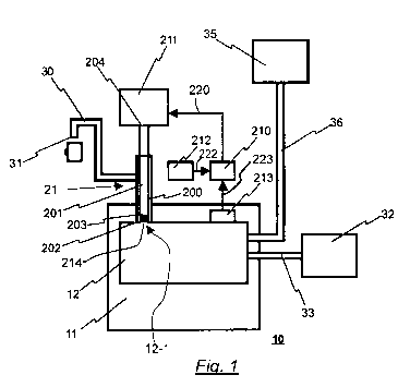
Fig. 1 shows a schematic illustration of a brewing
device 10 according to the invention 10 for producing a
coffee beverage. In the figure the brewing device 10
includes a green coffee container 35 from which green
coffee in powder form is automatically taken and
supplied via a green coffee feed line 36 to a brewing
unit 11. The brewing chamber 12 of the brewing unit 11
is further connected via a water feed line 33 with a
water tank 32, which looks after the fresh water
supply. The brewing chamber 12 further comprises an
outlet opening 12-1 for the particular brewed coffee.
CA 02821570 2013-06-13
- 12 -
At the outlet opening 12-1 of the brewing chamber 12 a
crema unit 21 is arranged which encompasses a crema
chamber 200 and a valve piston 201 protruding into the
crema chamber 200. The valve piston 201 encompasses a
stopper 202 which is arranged at an end of the valve
piston 201 facing the brewing chamber 12. The valve
piston 201 is configured such that it can be moved in
its longitudinal direction while being positioned in a
plurality of different specified positions (called
"movement positions" in the following).
In one of the specified positions (as indicated in fig.
1) the stopper 202 closes a coffee passage 214 which
connects the brewing chamber 12 with the crema chamber
200, with the coffee passage 214 leading into the
brewing chamber 12 at the outlet opening 12-1. In its
longitudinal direction furthermore the valve piston 201
can be moved in a direction facing away from the
brewing chamber 12 (upwards in fig. 1), so that the
valve piston 201 is able to assume one or more other
specified movement positions (not shown in fig. 1) in
which the valve piston 201 is arranged at a distance
from the coffee passage 214, so that the stopper no
longer closes the coffee passage 214 and brewed coffee
from the brewing chamber 12 can flow as required into
the crema chamber 200. The brewed coffee, after being
swirled through as required, flows into the crema
chamber 200 and in there, in an upper area, is directed
through an outlet line 30 to an outlet opening 31. The
valve piston 201 can be moved by means of a final
control element 211 such that its insertion depth into
the crema chamber 200 can be varied within wide limits.
The stopper 202, for example, may consist of rubber or
a comparable elastic material and serves to vary a
contact pressure towards the lower chamber end of the
crema chamber 200 by means of the final control element
CA 02821570 2013-06-13
- 13 -
211. In this way a gap which forms between the stopper
202 and the coffee passage 214 when the valve piston
201 is removed from the movement position shown in fig.
1 for letting coffee through from the brewing chamber
12 into the crema chamber 200 by varying the contact
pressure or possibly by lifting the valve piston 201
further, can be altered such that the brewed coffee
entering into the crema chamber 200 through this gap
comprises a crema which as regards its condition (for
example consistency or taste) and/or the amount of
particular crema produced is variable (changeable)
(depending on the particular movement position of the
valve piston 201). By moving the valve piston 201 in
direction of its end 204 on the side of the final
control element the amount of crema produced can be
reduced to a minimum.
In the embodiment shown a sensor 213 configured as a
pressure sensor is attached to the brewing chamber 12,
which measures the momentary water pressure of the
brewing water within the brewing chamber 12 during a
brewing operation. A measuring signal 223 recorded in
this way is directed to a control unit configured as a
regulator which in turn is supplied with a default
signal 222 by a setpoint-setting unit 212. The
setpoint-setting unit 212 may specify a regulating
variable such as a pressure to be maintained or a
movement position of the valve piston 201 corresponding
to the pressure to be maintained, which translates the
control unit 210 configured as a regulator into a
control signal 220. This control signal 220 is then fed
to the final control element 211, wherein the final
control element 211 is, as a rule, configured as a
motor, preferably a step motor.
As is evident from the block circuit diagram in fig. 2,
the control unit 210, the final control element 211.
CA 02821570 2013-06-13
- 14 -
the setpoint-setting unit 212 as well as the sensor 213
are interconnected to form a control loop which can be
implemented in a simple way. Alternatively it is of
course possible to provide, not a regulating operation
but merely a controlling operation. In this case, if
the final control element 211 is implemented as a step
motor for example, the setpoint specified by means of
the setpoint-setting unit 212 could, for example,
include the number of steps to be performed by the step
motor.
Fig. 3 shows a sectional view of the brewing unit 11,
wherein it can be seen that both the crema unit 21 and
the final control element 211 configured as a step
motor are housed entirely within the brewing piston 13.
The final control element 211 in this case is fastened
by means of a fastening device 215 within the brewing
unit 11 thereby ensuring reliable lifting and lowering
of the valve piston 201. As also revealed in fig. 3, a
coffee sieve 14 is formed on the coffee passage 214 to
which counter-pressure can be applied with the aid of
the valve piston 201 and the stopper 202. The coffee
sieve is provided for the purpose of retaining the
compressed coffee powder 40 within the brewing chamber
12 and to allow only the liquid components, i.e. the
brewed coffee, to pass in the direction of the coffee
passage 214.
In fig. 3 the valve piston 201 is shown in a situation
in which the stopper 202 is arranged at a distance D
from the coffee passage 214 (movement position S1 of
valve piston 201), so that the coffee passage 214 is
not closed by the valve piston 201 and thus exposed to
the passage of the coffee brewed in the brewing chamber
12. If, however, the valve piston 201 is moved into the
movement position SO shown in fig. 3, the stopper 202
closes the coffee passage 214.
CA 02821570 2013-06-13
- 15 -
As indicated in fig. 3 the valve piston 201 comprises a
central longitudinal bore 201-1 and encompasses at
least one connecting channel 201-2 which realises a
fluid connection between the crema chamber 200 and the
central longitudinal bore 201-1, and a connecting piece
201-3 which has one end of the outlet line 30 attached
to it, wherein the connecting piece 201-3 comprises a
bore 201-4, which realises a fluid connection between
the central longitudinal bore 201-1 and the outlet line
30.
The pressurised brewing water initially flows in
direction of the sieve 14, wherein the flow direction
of this pressurised brewing water is indicated by an
arrow marked with the reference symbol 41. During the
brewing operation the brewed coffee or the brewing
water passes through the coffee sieve 14 and the coffee
passage 214 into the crema chamber 200 while being
swirled through with differing intensity, depending on
the movement path of the valve piston 201 and, as
required, the counter-pressure from the stopper 202.
Accordingly the coffee beverage entering (through the
connecting channel 201-2 and the bores 201-1 and 201-4)
into the outlet line 30 configured as a tube comprises
a crema of greater or lesser intensity and variable
consistency (depending on the movement position which
the valve piston 201 assumes during the brewing
operation).
Further as revealed in the sectional view of fig. 4,
the brewing unit 11 is installed in a swivelling unit
which, by means of swivelling the brewing cylinder 15
and by means of moving the brewing piston 13 (in
longitudinal direction of the brewing piston 13) and by
moving the ejecting piston 16 (in longitudinal
direction of the ejecting piston 16), permits automatic
CA 02821570 2013-06-13
- 16 -
filling of the brewing chamber 12 with coffee powder
prior to the brewing operation and subsequent emptying
of the brewing chamber 12 following the completed
brewing operation (including removing the coffee powder
and, as required and if present, the remains of the
brewing water from the brewing chamber 12). Such
swivelling also causes swivelling of the outlet line 30
relative to the coffee outlet 31 not shown in fig. 4.
The above-mentioned automatic filling and emptying of
the brewing chamber 12 is known as such, e.g. from EP 0
559 620 Bl and will therefore not be explained in
detail here. By means of the solution according to the
invention it is therefore possible, following the
brewing operation, to determine the position of the
piston 201 such that the remaining residual liquid
flows back from the outlet line 30 through the coffee
passage 214 into the brewing chamber 12 and from there
into a drip tray or similar catchment device. This has
the effect of preventing any residual water in the
outlet line 30 from being sprayed out of the outlet
opening 31 during swivelling of the brewing cylinder
15, for example during automatic filling or emptying of
the brewing chamber 12.
As further revealed in fig. 4 a sensor 213 configured
as a pressure sensor is provided for measuring the
brewing water pressure during a brewing operation,
which pressure acts upon the brewing piston 13. This
pressure sensor 213 is connected with a control unit
210 not shown in fig. 4, which in turn is configured as
a regulator and which issues a control signal 220 again
not shown in fig. 4 to the final control element 211,
i.e. a step motor in fig. 4.
Fig. 5 finally represents a schematic illustration of a
brewing device 10 according to the invention similar to
that in fig. 1, wherein in this case the sensor 213 is
CA 02821570 2013-06-13
- 17 -
configured, not as a pressure sensor but as a position
sensor. Fig. 5 shows that this position sensor is
integrated with a housing of the final control element
211. The position sensor can thus determine e.g. the
movement position or the insertion depth of the valve
piston 201 and issue a measurement signal 223 to the
control unit 210 configured as a regulator. In fig. 5
the valve piston 201 is shown as being displaced or
moved into a position in which compared to the
illustration in fig. 1 less or no crema at all is
produced.
Figure 6 shows an assembly 21A comprising a crema unit
21 and a final control element 211, wherein the crema
unit 21 or the final control element 211 correspond to
the brewing device shown in fig. 1 to fig. 5 as regards
construction and function of the crema unit 21 or the
final control element 211. In fig. 1 to fig. 6
identical or similarly functioning parts are marked
with the same reference symbols. The arrangement of the
crema unit 21 and the final control element 211 in the
assembly 21A of fig. 6 is different from the
arrangement of the crema unit 21 and the final control
element 211 shown in fig. 3 and fig. 4 in that the
assembly 21A can be positioned independently of the
brewing unit 11, wherein the respective distance to the
brewing chamber 12 can be chosen at random. In
deviating from the construction of the brewing unit
shown in fig. 1 to fig. 5 the crema unit 21 and the
final control element 211 may be arranged outside the
brewing piston 13 of the brewing unit 10. In the
present example the assembly 21A encompasses a housing
21-1, in which the crema unit 21 and the final control
element 211 are arranged. In this variant the assembly
21A forms a unit which as a whole can be positioned at
a predetermined location.
CA 02821570 2013-06-13
- 18 -
As indicated in fig. 6 the assembly 21A comprises a
connecting piece 214-1, in which a coffee passage 214
leading into the crema chamber 200 is formed
(corresponding to coffee passage 214 of fig. 1 and 3-
5). One end of the tube 12-2 can be connected to the
connecting piece 214-1, whilst the other end (not shown
in fig. 6) can be connected to the brewing unit 11 in
order to establish a connection between the brewing
chamber 12 and the crema chamber 200 enabling coffee
brewed in the brewing chamber 200 to flow via the tube
12-2 into the coffee passage 214.
The assembly 21A of fig. 6 could, for example, replace
the crema unit 21 and the final control element 211 of
fig. 3 and fig. 4, wherein merely the coffee passage
214 of the assembly 21A would have to be connected via
the tube 12-2 with the outlet opening 12-1 of the
brewing chamber 12. Instead of the tube 12-2 another
suitable line, for example a pipeline, can of course be
used.
In fig. 6 the valve piston 201 is depicted in a
situation, in which the stopper 202 is arranged in the
movement position SO, thereby closing the coffee
passage 214. The valve piston 201 is movable in its
longitudinal direction by means of the final control
element 211, for example into the movement position S1
shown in fig. 6, in which the stopper 202 does not
close the coffee passage 214, thereby establishing a
fluid connection between the coffee passage 214 and the
bore 201-4 via the crema chamber 200, the connecting
channel 201-2 and the central longitudinal bore 201-1.
As also indicated in fig. 6, the assembly 12A comprises
a connecting piece 30-1 with a longitudinal through-
bore which is arranged on the housing 21-1 and serves
to establish a fluid connection between the bore 201-4
CA 02821570 2013-06-13
- 19 -
and the outlet line 30 for the particular produced
coffee beverage. As indicated in fig. 6 the connecting
piece 30-1 comprises two ends for this purpose, wherein
one of these ends is connectable with one end of the
outlet line 30 and the other end of the connecting
piece 30-1 is connected via a tube 30-2 with the
connecting piece 201-3 of the valve piston 201, so that
the particular produced coffee beverage can flow from
the crema chamber 200 via the tube 30-2 into the outlet
line 30.