Note : Les descriptions sont présentées dans la langue officielle dans laquelle elles ont été soumises.
CA 02822463 2013-06-19
WO 2012/106074 PCT/US2012/020864
MOLD-TOOL SYSTEM INCLUDING ACTUATOR CONFIGURED TO MOVE PLATE
ASSEMBLIES ATTACHED WITH VALVE-STEM ASSEMBLIES OF RUNNERS
TECHNICAL FIELD
An aspect generally relates to (but is not limited to) a mold-tool system
including (but not
limited to) a plate-actuator assembly coupled with a first movable-plate
assembly and with a
second movable-plate assembly, the plate-actuator assembly configured to move
the first
movable-plate assembly and the second movable-plate assembly in opposite
directions
between a valve-open position and a valve-closed position.
BACKGROUND
United States Patent Number 7086852 discloses a stack injection molding
apparatus has
first and second arrays of valve gate injection nozzles and separate
mechanisms for
independently actuating the nozzles of each array. A separate reciprocating
yoke plate
engages the valve pins of each nozzle array, and is actuated by either one
centrally located
actuator or a pair of symmetrically located actuators.
SUMMARY
The inventors have researched a problem associated with known molding systems
that
inadvertently manufacture bad-quality molded articles or parts. After much
study, the
inventors believe they have arrived at an understanding of the problem and its
solution,
which are stated below, and the inventors believe this understanding is not
known to the
public.
More and more, users of molding systems doing precision molding are calling
for
synchronous valve pin actuation for valve-gated hot runners. The valve pins
move together
as they are attached to a single plate that moves back and forth. Plate-
actuated systems
typically use hydraulics, pneumatics or electric motors to move the plate. As
these systems
become more accepted in the molding industry, molders are likely to move on to
stack hot
runners with plate actuated valve pins to increase molding-machine output.
Using known
plate actuation techniques, a stack hot runner with plate actuated valve pins
may have an
extremely large shut-height (which is a disadvantage).
According to one aspect, there is provided a mold-tool system (100),
comprising: a first
movable-plate assembly (102) being configured to attach with a first valve-
stem assembly
1
CA 02822463 2013-06-19
WO 2012/106074 PCT/US2012/020864
(202) of a first runner assembly (200); a second movable-plate assembly (104)
being
configured to attach with a second valve-stem assembly (204) of a second
runner assembly
(201); and a plate-actuator assembly (106) being coupled with the first
movable-plate
assembly (102) and with the second movable-plate assembly (104), the plate-
actuator
assembly (106) being configured to move the first movable-plate assembly (102)
and the
second movable-plate assembly (104) in opposite directions between a valve-
open position
and a valve-closed position.
Other aspects and features of the non-limiting embodiments will now become
apparent to
those skilled in the art upon review of the following detailed description of
the non-limiting
embodiments with the accompanying drawings.
DETAILED DESCRIPTION OF THE DRAWINGS
The non-limiting embodiments will be more fully appreciated by reference to
the following
detailed description of the non-limiting embodiments when taken in conjunction
with the
accompanying drawings, in which:
FIGS. 1A, 1B, 2A, 2B depict schematic representations of a mold-tool system
(100).
The drawings are not necessarily to scale and may be illustrated by phantom
lines,
diagrammatic representations and fragmentary views. In certain instances,
details not
necessary for an understanding of the embodiments (and/or details that render
other details
difficult to perceive) may have been omitted.
DETAILED DESCRIPTION OF THE NON-LIMITING EMBODIMENT(S)
FIGS. 1A, 1B, 2A, 2B depict the schematic representations (specifically, cross
sectional
views) of the examples of the mold-tool system (100). The mold-tool system
(100) may
include components that are known to persons skilled in the art, and these
known
components will not be described here; these known components are described,
at least in
part, in the following reference books (for example): (i) "Injection Molding
Handbook'
authored by OSSWALD/TURNG/GRAMANN (ISBN: 3-446-21669-2), (ii) "Injection
Molding
Handbook' authored by ROSATO AND ROSATO (ISBN: 0-412-99381-3), (iii)
"Injection
Molding Systems" 3rd Edition authored by JOHANNABER (ISBN 3-446-17733-7)
and/or (iv)
"Runner and Gating Design Handbook' authored by BEAUMONT (ISBN 1-446-22672-9).
It
will be appreciated that for the purposes of this document, the phrase
"includes (but is not
2
CA 02822463 2013-06-19
WO 2012/106074 PCT/US2012/020864
limited to)" is equivalent to the word "comprising". The word "comprising" is
a transitional
phrase or word that links the preamble of a patent claim to the specific
elements set forth in
the claim which define what the invention itself actually is. The transitional
phrase acts as a
limitation on the claim, indicating whether a similar device, method, or
composition infringes
the patent if the accused device (etc) contains more or fewer elements than
the claim in the
patent. The word "comprising" is to be treated as an open transition, which is
the broadest
form of transition, as it does not limit the preamble to whatever elements are
identified in
the claim.
The definition of the mold-tool system (100) is as follows: a system that may
be positioned
and/or may be used in an envelope defined by a platen system of the molding
system, such
as an injection-molding system for example. The platen system may include a
stationary
platen and a movable platen that is moveable relative to the stationary
platen. Examples of
the mold-tool system (100) may include (and is not limited to): a runner
system, such as a
hot runner system or a cold runner system, a runner nozzle, a manifold system,
and/or any
sub-assembly or part thereof, etc.
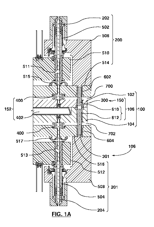
Referring now to FIGS 1A, 1B, 2A, 2B, the mold-tool system (100) may include
and is not limited
to: (i) a first movable-plate assembly (102), (ii) a second movable-plate
assembly (104), and
(iii) a plate-actuator assembly (106). The first movable-plate assembly (102)
may be
configured to attach with a first valve-stem assembly (202) of a first runner
assembly (200).
FIGS. 1A and 2A depict the first valve-stem assembly (202) positioned in a
valve-open
position, in which melt or a flowable resin may flow from a first nozzle
assembly (502). FIGS.
1B and 2B depict the first valve-stem assembly (202) positioned in a valve-
closed position, in
which melt or a flowable resin may not flow from the first nozzle assembly
(502). The second
movable-plate assembly (104) may be configured to attach with a second valve-
stem
assembly (204) of a second runner assembly (201). FIGS. 1A and 2A depict the
second
valve-stem assembly (204) positioned in the valve-open position, in which melt
or a flowable
resin may flow from a second nozzle assembly (504). FIGS. 1B and 2B depict the
second
valve-stem assembly (204) positioned in a valve-closed position, in which melt
or a flowable
resin may not flow from the second nozzle assembly (504). The plate-actuator
assembly
(106) may be coupled with the first movable-plate assembly (102) and with the
second
movable-plate assembly (104). The plate-actuator assembly (106) may be
configured to
move the first movable-plate assembly (102) and the second movable-plate
assembly (104)
in opposite directions between the valve-open position (as depicted in FIGS.
1A and 2A) and
3
CA 02822463 2013-06-19
WO 2012/106074 PCT/US2012/020864
the valve-closed position (as depicted in FIGS. 1B and 2B). The valve-open
position may be
defined as contact between the first movable-plate assembly (102) and the
second movable-
plate assembly (104). The valve-closed position may be defined as non-contact
between the
first movable-plate assembly (102) and the second movable-plate assembly
(104).
By way of example, the first runner assembly (200) may include (and is not
limited to) a first
nozzle assembly (502) that is connected with a first manifold-plate assembly
(506). The first
manifold-plate assembly (506) may include a first manifold assembly (510) that
defines a first
melt channel (511) that is used for distributing a resin (melt) to the first
nozzle assembly
(502). The first nozzle assembly (502) then conveys the resin to a mold
assembly (known
and not depicted). The first manifold-plate assembly (506) may also include a
first backing
plate (514), which may be used with the first manifold-plate assembly (506) to
house and
support the first manifold assembly (510). A first insulator (515) may be
positioned between
the first backing plate (514) and the first manifold assembly (510).
By way of example, the second runner assembly (201) may include (and is not
limited to) a
second nozzle assembly (504) that is connected with a second manifold-plate
assembly
(508). The second manifold-plate assembly (508) may include a second manifold
assembly
(512) that defines a second melt channel (513) that is used for distributing
the resin to the
second nozzle assembly (504). The second nozzle assembly (504) then conveys
the resin to
another mold assembly (known and not depicted). The second manifold-plate
assembly
(508) may also include a second backing plate (516), which may be used with
the second
manifold-plate assembly (508) to house and support the second manifold
assembly (512). A
second insulator (517) may be positioned between the second backing plate
(516) and the
second manifold assembly (512).
Referring now to FIGS 1A, 1B, 2A, 2B, the mold-tool system (100) may be
arranged such
that the plate-actuator assembly (106) may include (by way of example) and is
not limited to:
a gear assembly (150). The gear assembly (150) may be coupled to the first
movable-plate
assembly (102) and the second movable-plate assembly (104). The gear assembly
(150)
may be configured to align the first movable-plate assembly (102) with the
second movable-
plate assembly (104) so that a side-to-side movement is maintained between the
first
movable-plate assembly (102) and the second movable-plate assembly (104). In
addition,
the gear assembly (150) may be configured to permit simultaneous movement of
the first
movable-plate assembly (102) with the second movable-plate assembly (104) at a
matched
4
CA 02822463 2013-06-19
WO 2012/106074 PCT/US2012/020864
speed.
Referring now to FIGS 1A, 1B, 2A, 2B, the mold-tool system (100) may be
arranged such
that the plate-actuator assembly (106) may include (by way of example) and is
not limited to:
a gear-drive assembly (152). The gear-drive assembly (152) may be operatively
connected
with the gear assembly (150). The gear-drive assembly (152) may be configured
to move the
gear assembly (150) so that the first movable-plate assembly (102) and the
second movable-
plate assembly (104) are movable between the valve-open position and the valve-
closed
position.
By way of example, the gear assembly (150) may include (and is not limited to)
a bi-
directional ball screw assembly (300) connecting the first movable-plate
assembly (102) with
the second movable-plate assembly (104). The bi-directional ball screw
assembly (300) may
be configured such that along a first direction of rotation of the bi-
directional ball screw
assembly (300), the first movable-plate assembly (102) and the second movable-
plate
assembly (104) may move closer together; along a second direction of rotation
of the bi-
directional ball screw assembly (300), the first movable-plate assembly (102)
and the second
movable-plate assembly (104) may move further apart from each other. The bi-
directional
ball screw assembly (300) may be attached to each of the the first movable-
plate assembly
(102) and the second movable-plate assembly (104). By way of another example,
the gear
assembly (150) may include (and is not limited to) the gear assembly (150) may
include (and
is not limited to) a rack-and-pinion-gear assembly (not depicted but known)
connecting the
first movable-plate assembly (102) with the second movable-plate assembly
(104).
By way of further example, the first movable-plate assembly (102) may define a
first shaft
channel (602) that may be configured to receive the bi-directional ball screw
assembly (300).
The first shaft channel (602) may define a first threaded channel (610) that
may interact with
the bi-directional ball screw assembly (300). In addition, the the second
movable-plate
assembly (104) may define a second shaft channel (604) that may be configured
to receive
the bi-directional ball screw assembly (300). The second shaft channel (604)
may define a
second threaded channel (612) that may be configured to interact with the bi-
directional ball
screw assembly (300). The plate-actuator assembly (106) may include a
rotatable shaft (301)
of the bi-directional ball screw assembly (300), and the rotatable shaft (301)
may be received
in the first shaft channel (602) and the second shaft channel (604).
CA 02822463 2013-06-19
WO 2012/106074 PCT/US2012/020864
For FIGS. 1A, 2A, for the case were the first valve-stem assembly (202) is
positioned in the
valve-open position, an open space (700) exists between the first movable-
plate assembly
(102) and the first backing plate (514) of the first runner assembly (200),
and as well, an
open space (702) exists between the second movable-plate assembly (104) and
the second
backing plate (516) of the second runner assembly (201). For FIGS. 1B, 2B, for
the case
were the first valve-stem assembly (202) is positioned in the valve-closed
position, an open
space (710) exists between the first movable-plate assembly (102) and the
second movable-
plate assembly (104).
Referring now to FIGS, 1A, 1B, the mold-tool system (100) may be further
adapted so that
the gear-drive assembly (152) may include (by way of example and not limited
to) a spring
assembly (400). The spring assembly (400) may be coupled to the first movable-
plate
assembly (102) and the second movable-plate assembly (104). The spring
assembly (400)
may be configured to bias the first movable-plate assembly (102) and the
second movable-
plate assembly (104) so as to maintain the first valve-stem assembly (202) and
the second
valve-stem assembly (204) in the valve-open position. The spring assembly
(400) may be
used for return motion of the first movable-plate assembly (102) and the
second movable-
plate assembly (104), for example, when no other predetermined forces act on
the first
movable-plate assembly (102) and the second movable-plate assembly (104).
Referring now to FIGS, 1A, 1B, the mold-tool system (100) may be further
adapted so that
the gear-drive assembly (152) may further include (by way of example and not
limited to) a
bladder assembly (402). FIG. 1A depicts the bladder assembly (402) in a
deflated state. FIG.
1B depicts the bladder assembly (402) in an inflated state. The bladder
assembly (402) may
be positioned between the first movable-plate assembly (102) and the second
movable-plate
assembly (104). The bladder assembly (402) may be configured to (as depicted
in FIG. 1B)
inflate, abut, move and then maintain the first movable-plate assembly (102)
and the second
movable-plate assembly (104) in the valve-closed position. The bladder
assembly (402) may
be configured to deflate (as depicted in FIG. 1A) so as to permit movement of
the first
movable-plate assembly (102) and the second movable-plate assembly (104) back
to the
valve-open position.
It will be appreciated that the bladder assembly (402) may be used with
another equivalent
structure other that the spring assembly (400), so long as the first valve-
stem assembly (202)
and the second valve-stem assembly (204) are returned to the valve-open
position upon
6
CA 02822463 2013-06-19
WO 2012/106074 PCT/US2012/020864
deflation of the bladder assembly (402). For example the another equivalent
structure may
be configured to include an electrically-driven actuator that may be
configured to push on
each side (such as a nozzle side) of each of the first movable-plate assembly
(102) and the
second movable-plate assembly (104). For example, another bladder (not
depicted) may be
used to push the first movable-plate assembly (102) and the second movable-
plate assembly
(104) apart (to the valve-closed position), and then separate bladders may be
used to push
each plate to the valve-open position, etc.
For the case where the spring assembly (400) is used as depicted, the bladder
assembly
(402) may be configured to inflate, abut, move and then maintain the first
movable-plate
assembly (102) and the second movable-plate assembly (104) in the valve-closed
position
while overcoming the spring assembly (400). In addition, the bladder assembly
(402) may be
also configured to deflate so as to permit the spring assembly (400) to move
the first
movable-plate assembly (102) and the second movable-plate assembly (104) back
to the
valve-open position. For the case where the gear assembly (150) includes the
bladder
assembly (402), the gear assembly (150) may further include (and is not
limited to) the bi-
directional ball screw assembly (300) connecting the first movable-plate
assembly (102) with
the second movable-plate assembly (104). For the case where the gear assembly
(150)
includes the bladder assembly (402), the gear assembly (150) may further
include (and is not
limited to) a rack-and-pinion-gear assembly (not depicted but known)
connecting the first
movable-plate assembly (102) with the second movable-plate assembly (104).
Referring now to FIGS. 2A and 2B, the mold-tool system (100) may be adapted
such that the
gear-drive assembly (152) may include (and is not limited to): a motor
assembly (500), and a
pulley and belt assembly (503). The pulley and belt assembly (503) may be
configured to
couple the motor assembly (500) to the gear assembly (150). The motor assembly
(500) may
be configured to move the first movable-plate assembly (102) and the second
movable-plate
assembly (104) between the valve-open position and the valve-closed position.
Referring now to FIGS. 2A and 2B, for the case where the gear-drive assembly
(152)
includes the motor assembly (500) and the pulley and belt assembly (503), the
gear
assembly (150) may include (by way of example) the bi-directional ball screw
assembly (300)
connecting the first movable-plate assembly (102) with the second movable-
plate assembly
(104).
7
CA 02822463 2013-06-19
WO 2012/106074 PCT/US2012/020864
Referring now to FIGS. 2A and 2B, for the case where the gear-drive assembly
(152)
includes the motor assembly (500) and the pulley and belt assembly (503), the
gear
assembly (150) may include (by way of example) a rack-and-pinion-gear assembly
(not
depicted and known) connecting the first movable-plate assembly (102) with the
second
movable-plate assembly (104).
One purpose of the mold-tool system (100) may be to provide an actuation
system that may
enable stack hot runner systems with plate actuated valve pins to be produced
with smaller
shut-heights relative to what is available today. Single face hot runners with
plate actuated
valve pins are currently available with pneumatic, hydraulic or electric
actuation means.
Known systems with pneumatic or hydraulic actuation typically use a number of
piston
assemblies that push or pull the first movable-plate assembly (102) and the
second
movable-plate assembly (104). These known piston assemblies consume
significant
amounts of space in the hot runner assembly. Systems using an electric motor
to actuate
the first movable-plate assembly (102) and the second movable-plate assembly
(104)
typically have belt, gear or ball screw drives that move the first movable-
plate assembly
(102) and the second movable-plate assembly (104) using some form of cam
mechanisms.
These known systems may also suffer from similarly large hot runner shut-
heights. Placing
two independently actuated systems back to back for a stack mold may result in
a
prohibitively large hot runner shut-height. The mold-tool system (100)
provides or permits a
smaller hot runner shut-height by combining the motion and actuation systems
for the first
movable-plate assembly (102) and the second movable-plate assembly (104) into
a
singular system.
The plate-actuation system for a single faced hot runner typically consists of
a drive system,
which moves the first movable-plate assembly (102) and the second movable-
plate
assembly (104), an alignment bearing system that ensures consistent movement
and
physical stops that define the stroke of the first movable-plate assembly
(102) and the
second movable-plate assembly (104) (valve pin open and close). The
integration of this
actuation system into a hot runner requires a significant amount of plate
thickness to be
added, which in turn increases the overall mold shut-height. For known stack
hot runner
using individual pneumatic pistons to actuate each valve pin, the standard
course of action
would essentially be to place two single face hot runners back to back
(maintaining
independent actuation for all valve pins). If the same principle were to be
applied to a stack
system with plate-actuated valve pins, that is placing two independent plate-
actuation
8
CA 02822463 2013-06-19
WO 2012/106074 PCT/US2012/020864
systems back to back, the result may likely increase the hot runner shut-
height
(disadvantage) so much so that the overall mold shut-height may be too large
to fit in an
available injection molding machine.
Combining some or all of the components of two back to back plate-actuation
systems into
one, may provide an opportunity to reduce the hot runner shut-height. For
example, two
back to back plates may be actuated (in opposite directions) using the same
drive system,
and/or the alignment bearing system may be shared between the first movable-
plate
assembly (102) and the second movable-plate assembly (104), and/or both the
first
movable-plate assembly (102) and the second movable-plate assembly (104) may
share a
physical stop that limits the stroke of each of the first movable-plate
assembly (102) and the
second movable-plate assembly (104).
It will be appreciated that the assemblies and modules described above may be
connected
with each other as may be required to perform desired functions and tasks that
are within
the scope of persons of skill in the art to make such combinations and
permutations without
having to describe each and every one of them in explicit terms. There is no
particular
assembly, components, or software code that is superior to any of the
equivalents available
to the art. There is no particular mode of practicing the inventions and/or
examples of the
invention that is superior to others, so long as the functions may be
performed. It is
believed that all the crucial aspects of the invention have been provided in
this document.
In a back to back stack hot runner system with plate-actuated valve pins, the
first movable-
plate assembly (102) and the second movable-plate assembly (104) may move
towards
each other to open the valve pins and away from each other to close the valve
pins. The
proposed invention seeks to reduce hot runner shut-height by combining
components or
functions between the first movable-plate assembly (102) and the second
movable-plate
assembly (104).
In one example, the drive system that moves the first movable-plate assembly
(102) and
the second movable-plate assembly (104) further apart (to close the valve
stems) may be
shared. An inflatable bladder may be positioned between the first movable-
plate assembly
(102) and the second movable-plate assembly (104), such that when the bladder
is inflated,
the first movable-plate assembly (102) and the second movable-plate assembly
(104) are
pushed apart, thus moving the valve pins to the valve-closed position.
9
CA 02822463 2013-06-19
WO 2012/106074 PCT/US2012/020864
In another example, an alignment bearing system may be shared between the
first
movable-plate assembly (102) and the second movable-plate assembly (104). A bi-
directional lead screw may be used to ensure that both the first movable-plate
assembly
(102) and the second movable-plate assembly (104) move the same distance (even
in the
opposite direction). A nut follower may be located on each lead screw
direction, such that
as the screw rotates in one direction, the nuts move further apart, and upon
reversing the
direction of rotation, the nuts move closer together. For each lead screw in
the system, one
nut may be mounted to each of the first movable-plate assembly (102) and the
second
movable-plate assembly (104), thus tying the movement of the first movable-
plate assembly
(102) and the second movable-plate assembly (104) together. In this example,
the lead
screw may be used for alignment and synchronous movement only (with a separate
drive
system), or the movement of the first movable-plate assembly (102) and the
second
movable-plate assembly (104) may be driven by the screw rotation.
In another example, a physical stop that defines the amount of stroke the
first movable-
plate assembly (102) and the second movable-plate assembly (104) may be
capable of
being actuated and may be shared. The shared physical stop may be mounted in
the hot
runner plates, or the first movable-plate assembly (102) and the second
movable-plate
assembly (104) may in fact stop on themselves, such that when the valve pins
are in the
valve-open position the first movable-plate assembly (102) and the second
movable-plate
assembly (104) are in contact and restrict each other's motion to further move
the pin
position.
It is understood that these examples described above are some examples of the
mold-tool
system (100). Someone skilled in the art of mechanical system design may be
capable of
devising a number of different arrangements in which some part of the
actuation system is
shared between the first movable-plate assembly (102) and the second movable-
plate
assembly (104) so as to actuate valve pins in different directions. Also,
components from
the different example listed above may be combined to make a more integrated
plate
actuation system.
It is understood that the scope of the present invention is limited to the
scope provided by
the independent claim(s), and it is also understood that the scope of the
present invention
is not limited to: (i) the dependent claims, (ii) the detailed description of
the non-limiting
embodiments, (iii) the summary, (iv) the abstract, and/or (v) description
provided outside of
CA 02822463 2013-06-19
WO 2012/106074 PCT/US2012/020864
this document (that is, outside of the instant application as filed, as
prosecuted, and/or as
granted). It is understood, for the purposes of this document, the phrase
"includes (and is
not limited to)" is equivalent to the word "comprising". It is noted that the
foregoing has
outlined the non-limiting embodiments (examples). The description is made for
particular
non-limiting embodiments (examples). It is understood that the non-limiting
embodiments
are merely illustrative as examples.
11