Note : Les descriptions sont présentées dans la langue officielle dans laquelle elles ont été soumises.
CA 02823398 2013-08-09
IMPROVED GOLF CLUB GRIP
RELATED APPLICATIONS
[0001] [Not Applicable]
FEDERALLY SPONSORED RESEARCH OR DEVELOPMENT
[0002] [Not Applicable]
[MICROFICHE/COPYRIGHT REFERENCE]
[0003] [Not Applicable]
BACKGROUND OF THE INVENTION
[0004] A good grip is desirable when wielding any hand-held object. A firm
and comfortable grip is important when using many hand-held tools equipped
with a handle or shaft, such as hammers and axes. Moreover, many sports
require
a player to grip a handle or shaft on a piece of sporting equipment, e.g.
tennis,
cycling, hockey, golf, etc. Golfers for example strive for consistency, and a
comfortable, firm grip with proper finger placement is one of the keys to a
consistent golf game. Nevertheless, the typical club grip used by many golfers
does not promote a comfortable, firm grip or proper finger placement.
[0005] The typical golf club grip is a single-layer molded rubber grip that
has a
pre-determined thickness and durometer. The durometer or hardness of the club
grip is important because a player's grip on the club will not feel secure if
the grip
is too hard or too soft. The right club grip "feel" varies widely among
golfers.
Most club grips, however, are only available in a few select levels of feel,
such as
soft, medium, or hard.
[0006] One way to improve club grip feel is to construct grips from multiple
layers of material having different durometers. For example, Royal Precision's
CA 02823398 2013-08-09
Multi-Density Grip employs a low durometer color compound layer over a hard
black inner core layer. Royal Precision advertises that the soft outer layer
provides a custom grip "feel," while the harder inner layer maintains
stability by
reducing torque and twisting at impact.
[00071 A similar design is used in existing cycle grips. One example of such
grips are the ZyGo cycle grips made by AIME. ZyGo grips have an inner-
skeleton molded out of a hard rubber compound surrounded by a softer, tackier
outer layer. A'ME advertises that the hard inner layer prevents torque between
the handle bar and the rider's hands, while the softer outer layer provides
increased grip feel.
[0008] Grips with multiple layers, similar to standard single-layer grips, are
typically available only available in a few select layer durometers. Thus,
existing
multiple-layer grips are similarly limited in their level of club grip feel.
In
addition, multiple layer grips do not address the problem of proper finger
placement. Without a physical guide on the club grip, it is often difficult
for
beginning and intermediate players to locate the proper hand placement on the
club gip. Thus, many players vary the placement of their hands and fingers on
the club from shot to shot. This is a major contributor to a golfer's lack of
consistency on the golf course.
[0009] Most club grips lack any physical contours that could assist the golfer
with proper and consistent finger placement when gipping the club. This is
because the typical club grip is manufactured to comply with the rules of the
United States Golf Association ("USGA"), which call for a club grip that is
circular in cross section with no bulges or concavity. Nevertheless, there
have
been several attempts to improve the consistency in golf grip hand and finger
placement through the addition of physical bulges or concavity in a golf grip.
[00101 For instance, U.S. Patent Nos. 5,427,376 ("'376"), 5,480,146 ("'146"),
and 6,540,621 ("621") describe grips that are pre-shaped or pre-molded for a
typical golfer's fingers. Indentations formed or molded onto the outer surface
of
the club grip guide the player's fingers and hands to the same location each
time
2
CA 02823398 2013-08-09
they grab the club. Yet, to accommodate the indentations and the bulges that
indicate finger and hand placement, these grips are generally quite large and
bulky. Another problem associated with the formed or molded indentations in
these grips is that the bulges and concavities are obvious to other players,
which
can be a source of embarrassment for the player. Of course, these club grips
also
violate the USGA rules.
[00111 Furthermore, because the grips disclosed by '376, '146, and '621
references are molded or formed to accommodate the hands and fingers of a
typical golfer, the grips are not tailored to the physical and style
characteristics of
the individual player. Thus, these grips are unable to accommodate the
differences in golfers' hand sizes, finger lengths, grip styles (e.g., the
overlapping.
grip, the 10-finger grip, the interlocking grip, etc.), or a combination
thereof.
[0012] There have been attempts to offer a custom-mold club grip that improves
the consistency of club grip finger placement to accommodate the unique
physical
characteristics of a player's hands. One such attempt by a company called Fit
Grip requires that a player grip a pre-heated material forming the club grip
for a
period of approximately 30 seconds, during which time indents are formed in
the
soft grip material at precisely the points where the hands and fingers contact
the
grip. After th.e grip has cooled, the impression remains permanently molded in
the club. The club grip is capable of being molded additional times if
necessary.
[0013] Although the molding of the club grip produces contours custom-fitted
to
each golfer's hands, the resulting grip is still relatively large, obvious,
and fails to
conform to the USGA rules. An additional drawback is that the molded club gip
must be fitted by a trained professional. Many avid golfers enjoy the work
required to re-grip their clubs. By performing the re-grip themselves, golfers
get
a more intimate feel for their golf equipment and a greater sense of
confidence
when the equipment is used on the course.
[0014] It is an object of the present grips to provide an adjustable level of
overall grip durometer, or "feel," in a single grip. It is another object of
the
present grips to instill confidence in the player by increasing the surface
area of
3
CA 02823398 2013-08-09
the grip in contact with the player's hands. It is yet another object of the
present
grips to provide a physical guide to assist in consistent and proper finger
placement on a grip that is outwardly circular in cross section with no
obvious
bulges or concavity. It is an additional object of the present grips to
provide a
grip that may be custom-fitted by the player. Individual embodiments of the
present gips may address some or all of these objectives.
4
CA 02823398 2013-08-09
BRIEF SUMMARY OF THE INVENTION
[0015] The present grips are directed to an improved gripping apparatus and
method of use, including an improved golf club grip.
[0016] A preferred embodiment is, for example, a golf club grip that comprises
an outer layer disposed around an inner layer. The inner layer has a higher
durometer than the outer layer, which improves grip feel. The inner layer is
also
molded or moldable to substantially conform to the player's grip, thereby
facilitating consistent finger placement. The outer layer maintains a
substantially
circular cross section when not gripped. Alternatively, the inner layer may be
omitted and the shaft itself can be molded to substantially conform to a
player's
grip. In addition, a compression layer may be employed in addition to the
outer
layer to compress the outer layer to ensure that the outer layer maintains a
circular
cross section over the molded inner layer.
[0017] The preferred embodiment also may comprise a cavity disposed between
an outer layer and an inner layer disposed around a shaft., or the shaft
itself. The
cavity may be expandable, and it may comprise a single space, or multiple
subchambers. The subchambers may or may not be open to one another. The
cavity may receive various substances, such as hardening agents, foam, or
viscous
liquids, to promote long or short-term conformity of the grip to a player's
hands.
Air Or other gases may also be added or removed from the cavity to alter
overall
grip durometer, or feel. A valve may be provided for access to the cavity.
[0018] The preferred embodiment also may comprise an apparatus comprising a
first material having a first durometer, and a second material having a second
durometer. The first durometer is higher than the second durometer. The second
material is disposed around the first material and positioned to substantially
correspond to the player's finger placement, while the first material is
positioned
to correspond to areas of the grip that are not in contact with the player's
fingers.
When gripped, this arrangement guides the player's hands and fingers to the
low
durometer areas of the grip, which when gripped provide, in effect, concave
CA 02823398 2013-08-09
impressions in the grip. When the grip is released, these low durometer areas
return to their normal shape, giving the grip a substantially circular cross-
section.
[0019] Alternatively, the durometer of the first material may be lower than
the
durometer of the second material. When gripped, this arrangement guides the
player's hands and fingers to the areas of the grip where the low durometer
inner
material is the thickest.
[0020] The preferred embodiment may be manufactured as a wrap and wound
around the club shaft. This wrappable grip may contain cavities, which may in
turn contain other substances or materials to enhance the players grip on the
club.
BRIEF DESCRIPTION OF THE DRAWINGS
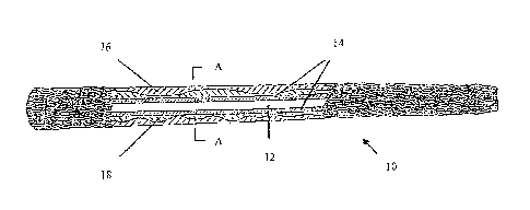
[0021] Fig. 1 is a cutaway view of a golf club grip, illustrating an outer
layer
disposed around a molded inner layer.
[0022] Fig. 2 is a cross section of the grip depicted in Fig. 1 along section
line
A-A, further illustrating the relationship of the inner and outer layers.
[0023] Fig. 3 is a cutaway view of the grip depicted in Fig. 1 showing the
club
shaft and molded inner layer.
[0024] Fig. 4 is a cutaway view of a golf club grip illustrating a moldable
inner
layer disposed between the club shaft and an outer layer.
[0025] Fig. 5 is a cross section of the grip depicted in Fig. 4 along section
line
B-B before the inner layer is molded.
[0026] Fig. 6 is a cross section of the grip depicted in Fig. 4 along section
line
B-B as the inner layer is being molded.
[0027] Fig. 7 is a cross section of the grip depicted in Fig. 4 along section
line
B-B after the inner layer is molded.
[0028] Fig. 8 is a cutaway view of a golf grip with aspects of the present
invention, illustrating an outer layer disposed about a molded club shaft.
[0029] Fig. 9 is a cross section of the grip depicted in Fig. 8.
6
CA 02823398 2013-08-09
[00301 Fig. 10 is a cutaway view of a golf club grip, illustrating a cavity
comprising sub-chambers disposed between an outer layer and an inner layer.
[0031] Fig. 11 is a cross section of the grip depicted in Fig. 10 along
section line
C-C, illustrating a landing and the sub-chambers between the inner and outer
layers.
[0032] Fig. 12 is a cross section (lithe grip depicted in Fig. 10 along
section line
C-C with a viscous gel in the sub-chambers before gripping.
[0033] Fig. 13 is a cross section of the grip depicted in Fig. 10 along
section line
C-C with a viscous gel in the sub-chambers during gripping.
[0034] Fig. 14 is a cross section of the grip depicted in Fig. 10 along
section line
C-C with a viscous gel in the sub-chambers shortly after the grip is released.
[0035] Fig. 15 is a cross section of the grip depicted in Fig. 10 along
section line
C-C with a viscous gel in the sub-chambers a substantial time after the grip
is
released.
[0036] Fig. 16 is a cross section of a golf club grip illustrating an
unpressurized
subchamber disposed between an outer layer and an inner layer during gripping.
[0037] Fig. 17 is a cross section of the grip depicted in Fig. 16 illustrating
a
pump pressurizing the subehamber.
[0038] Fig. 18 is a cross section of the grip depicted in Fig. 16 illustrating
a
pressurized cavity disposed between an outer layer and an inner layer during
gripping.
[00391 Fig. 19 is a cutaway view of a golf club grip illustrating a syringe
containing a hardening agent positioned in a cavity comprised of subchambers.
[0040] Fig. 20 is a cutaway view of the grip depicted in Fig. 19 after a
hardening agent has been injected into the subchambers.
[0041] Fig. 21 is a cross section of the grip depicted in Fig. 19 along
section line
D-D before the hardening agent is introduced.
7
CA 02823398 2013-08-09
[0042] Figure 22 is a cross section of the grip depicted in Fig. 20 along
section
line D-D after the hardening agent is introduced.
[0043] Fig. 23 is a cross section of the grip depicted in Fig. 20 along
section line
1)-13 after the hardening agent is introduced during gripping.
[0044] Fig. 24 is a cross section of the grip depicted in Fig. 20 along
section line
D-D after the hardening agent has hardened and the grip is released.
[0045] Fig. 25 is a cutaway view of a golf club grip illustrating a cavity
comprised of subchambers disposed between an outer layer and the club shaft.
[0046] Fig. 26 is a cross section of the grip depicted in Fig. 25 along
section line
E-E, illustrating the relationship of the cavity to the shaft and outer layer.
[0047] Fig. 27 is a cross section of the grip depicted in Fig. 25 along
section line
F-F, illustrating the relationship of the cavity to the shaft and outer layer
at a point
including an outer layer landing.
[0048] Fig. 28 is a cutaway view of a golf club grip, illustrating a shaped
low
durometer layer and a shaped high durometer layer disposed around the club
shaft
[0049] Fig. 29 is a cross section of the grip depicted in Fig. 28 along
section line
G-G, representing an area of the grip with a high durometer layer.
[0050] Fig. 30 is a cross section of the grip depicted in Fig. 28 along
section line
H-H, representing an area of the grip including high and low durometer layers.
100511 Fig. 31 is a cross section of the grip depicted in Fig. 28 along
section line
I-I, representing an area of the grip with a low durometer layer.
100521 Fig. 32 is a cutaway view of a golf club grip, illustrating a shaped
low
durometer layer and a shaped high durometer layer disposed around an inner
layer.
[0053] Fig. 33 is a cross section of the gip depicted in Fig. 32 along section
line
3-.1, representing an area of the grip with a high durometer layer disposed
around
the inner layer.
8
CA 02823398 2013-08-09
[0054] Fig. 34 is a cross section of the grip depicted in Fig. 22 along
section line
K-K, representing an area of the grip including high and low durometer layers
disposed around the inner layer.
[00551 Fig 35 is a cross section of the grip depicted in Fig. 22 along section
line
L-L, representing an area of the grip with a low durometer layer disposed
around
the inner layer.
[0056] Fig. 36 is a cutaway view of a golf club gip, illustrating a shaped low
durometer layer and a shaped high durometer layer disposed between an outer
layer and the club shaft.
[0057] Fig. 37 is a cross section of the gip depicted in Fig. 36 along section
line
M-M, representing an area of the grip with a high durometer layer disposed
between the outer layer and the club shaft. =
[00581 Fig. 38 is a cross section of the grip depicted in Fig. 36 along
section line
N-N, representing an area of the grip including high and low durometer layers
disposed between the outer layer and the club shaft.
[00591 Fig. 39 is a cross section of the grip depicted in Fig. 36 along
section line
0-0, representing an area of the grip with a low durometer layer disposed
between the outer layer and the club shaft.
[0060] Fig. 40 is a side view of a golf club grip illustrating a wrap grip as
it is
wrapped around the club shaft.
[0061] Fig. 41 is a cutaway view of the wrap grip of Fig. 40 illustrating a
cavity
comprised of subchambers disposed between an outer layer and an inner layer.
[0062] Fig. 42 is a cutaway view of the wrap grip of Fig. 40 showing a
moldable
substance M the subchambers.
[0063] Fig. 43 is a cutaway view of the wrap grip of Fig. 42 during gripping
showing the molded subchambers.
10064] Fig. 44 is a cutaway view of the wrap grip of Fig. 42 showing the
molded subchambers after the grip is released.
9
CA 02823398 2013-08-09
100651 Fig. 45 is a kit illustrating golf club grips, an epoxy injector, tape,
and
solvent.
DETAILED DESCRIPTION OF THE INVENTION
[0066] Figure 1 represents a preferred embodiment in the form of a golf club
grip 10, which includes an outer layer 16 and an inner section, in this case
inner
layer 18. Outer layer 16 is disposed around inner layer 18, which is in turn
disposed around shaft 12 in contact with shaft walls 14.
[0067] The durometer of inner layer 18 is higher than the durometer of outer
layer 16. For example, inner layer 18 may formed from rubber, while outer
layer
16 is formed from closed cell foam. Outer layer 16 may also be formed from
viscoelastic foam, in which case the indentations from the player's grip would
remain visible in outer layer 16 for a short amount of time before outer layer
16
returned to a substantially circular cross section. This permits players to
quickly
find their proper grip by sight between separate swings performed in rapid
succession.
[0068] Inner layer 18 is shown molded to substantially conform to a player's
grip, being thicker in non-contact areas sections of golf club grip 10 and
thinner in
contact areas. Thus, the player would be guided into a consistent gripping
position at the thinnest portions of inner layer 18, or conversely at the
thickest
portions of outer layer 16. Meanwhile, when golf club grip 10 is not in use,
outer
layer 16 maintains a substantially circular cross section of golf club grip 10
while
conforming to the contours of inner layer 18 as seen in Figure 2.
[0069] Figure 3 depicts molded inner layer 18 of golf club grip 10 disposed
about club shaft 12. Outer layer 16 is not shown to emphasize the physical
protrusions and concavities of inner layer 18 that serve to guide a player's
grip
into a firm and proper position.
[0070] Inner layer 18 can be pre-configured for an approximate fit, as
discussed
above, or inner layer 18 can be molded to custom-fit to the player's grip. In
either
CA 02823398 2013-08-09
case, outer layer 16 maintains a substantially circular cross section of golf
club
grip 10.
[0071] Figure 4 depicts golf grip 20 having a moldable inner layer 28 disposed
between an outer layer 26 and club shaft 22 with wall 24. Moldable inner layer
28 is comprised of a moldable material, such as clay. Other materials may be
used as recognized by those skilled in the art. A custom-fit can be achieved
by
simply gripping un-molded golf club grip 20 with a firm and proper grip to
conform outer layer 26 and inner layer 28 to the player's grip, and then
releasing
golf club grip 20. Upon release, moldable inner layer 28 remains substantially
conformed to the player's grip, but outer layer 26 returns to a circular cross
section.
[0072] In this configuration, the golfer can shape and re-shape the grip to
his
hands any number of times and the grip will retain the impressions of the
golfer's
hands until he/she desires to reshape the grip. For example, some advanced
players will use different grips for certain specialty shots (draw, fade,
punch,
chip). If a specialty shot requiring a specific grip is desired, the golfer
can simply
rework the inner layer to the necessary shape.
[0073] Various durometers of the clay may be employed such that it may take
considerable effort to reshape. In such instances, the grip would have a
greater
tendency to retain its shape over prolonged periods of time, e.g. weeks,
months or
even years.
[00741 Figures 5 through 7 show in cross-section the sequence of molding
moldable inner layer 28 along section line B-B. Figure 5 is a cross section of
golf
grip 20 depicted in Figure 4 along section line B-B shown before gripping golf
grip 20. At this point, club shaft 22, moldable inner layer 28, and outer
layer 26
all possess a substantially circular cross section.
[0075] Figure 6 is a cross section of golf grip 20 depicted in Figure 4 along
section line B-B when gripped. When golf grip 20 is gripped, the players hands
or fingers 27 compress both outer layer 26 and moldable inner layer 28. As
depicted in Figure 7, when golf grip 20 is released, outer layer 26 returns to
a
11
CA 02823398 2013-08-09
substantially circular cross section. Moldable inner layer 28, however,
retains the
impressions of the player's grip. The impressions will act to guide the
player's
grip into the same position the next time the player grips golf grip 20.
[0076] For a short term custom-fit, inner layer 28 of golf club grip 20 could
be
comprised of a closed cell foam, viscoelastic foam, or other material that
regains
its shape after deformation a short period of time later. This short-term
custom-fit
is particularly useful in golf because players may move their grip up or down
the
club depending on the distance to the pin or the desired ball trajectory, e.g.
punch
and chip shots. In this embodiment, inner layer 28 would have a lower
durometer
than outer layer 26. Thus, outer layer 26 and inner layer 28 maintain a
substantially circular cross section until gripped, whereupon the impressions
of
the player's hands and fingers would be retained for a short time by inner
layer
28. These impressions make inner layer 28 thicker when the grip is released
and
outer layer 26 returns to a substantially circular cross section. Inner layer
28
would gradually return to a circular cross section, but in the meantime the
impressions of the player's grip serve to guide the player's grip into the
original
gripping position at the thicker portions of inner layer 28. This embodiment
would be useful for making multiple shots in quick succession, as encountered
on
the driving range for example. For a pre-configured fit, a portion of club
shaft
may be used as the inner section in place of inner layer.
[0077] Figure 8 depicts golf grip 30 having an outer layer 36 and a molded
club
shaft 32 with wall 34 in place of a molded inner layer. In this embodiment, a
portion of club shaft 32 is pre-configured to substantially conform to a
player's
grip, while outer layer 36 maintains a substantially circular cross section of
golf
club grip 30. When golf grip 30 is gripped, the protrusions and concavities
along
the molded section of club shaft 32 act to guide the player's grip into a
consistent
and proper position.
[0078] Figure 9 shows a random cross section of golf grip 30 shown in Figure
8.
Molded shaft wall 34 has a higher durometer than outer layer 36. Thus, when
golf grip 30 is gripped by the player, outer layer 36 will compress under the
12
=
CA 02823398 2013-08-09
player's grip to roughly conform to the contours of molded shaft wall 34. When
released, outer layer 36 of golf grip 30 will return to a substantially
circular cross
section quickly, or over time, depending on the material used. to form outer
layer
36.
[00791 Figure 10 depicts yet another embodiment of a golf club grip 40. In
this
embodiment, a cavity comprised of a series of sub-chambers 43 is located
between outer layer 46 and an inner layer 48, which is disposed around shaft
42
with shaft wall 44. The addition of inner layer 48 facilitates the adhesion of
golf
club grip 40 to shaft 12, and seals sub-chambers 43 tightly. Connection points
47
operably connect inner layer 48 to outer layer 46. Sub-chambers 43 may be in
communication with one another, or constitute completely separate chambers.
[00801 Figure 11 depicts a 'cross section of golf grip 40 of Figure 10 taken
at
section line C-C. Subchambers 43 function to lower the overall durometer of
golf
grip 40 as compared to areas of golf grip 40 over connection points 47. Thus,
the
player's grip is guided to the regions of overall low durometer located over
subcharnbers 43, which provides a consistent grip along the length of golf
grip 40,
even if players move their grip up or down the length of golf grip 40. Figure
11
shows three sets of sub-chambers 43 located between outer layer 46 and inner
layer 48, but the configuration of sub-chambers 43 may Vary, and the use of
three
sub-chambers 43 in this embodiment is meant only as an example.
[00811 To achieve a desired grip feel, the firmness of golf club grip 40 over
sub-chambers 43 in between landings 47 can be adjusted by adding a substance
to
sub-chambers 43. This substance could be added by the player or the
manufacturer. For example, a viscous liquid, such as a gel, could be
introduced
into sub-chambers 43 to increase the feel of golf club grip 40. The gel would
conform to the hand impressions of the golfer and thus provide the desired
increased surface area for the golfer's hands. This has the desired effect of
providing increased "feel" for the golfer when taking a swing at the ball, yet
the
grip may then revert back to its circular cross section shortly following
release of
the grip. The sequence of events is depicted in Figures 12 through 15.
13
CA 02823398 2013-08-09
[0082] Figure 12 depicts the cross section of Figure 10 along section line C-C
containing a viscous gel 45. In Figure 13, a player grips golf grip 40 and
fingers
49 are depicted compressing outer layer 46 and gel-containing subchambers 43
under fingers 49. Inner layer 48 retains a substantially circular cross
section.
[0083] Figure 14 depicts golf grip 40 immediately after the player's grip is
released. Outer layer 46 has reverted to its substantially circular cross
section, but
compressed gel-containing subchambers 43 retain the impression of the player's
fingers 49. Over time, gel-containing subchambers 43 may revert to
substantially
their original configuration as shown in Figure 15.
[0084] Depending on the viscosity of the gel 45 and the internal structure of
golf
grip 40, the time it takes for gel-containing subchambers 43 to revert back to
substantially their original configuration may be fractions of a second to
several
minutes. If gel-containing sub-chambers 43 are in fluid communication, there
will be a relocation or shifting of the gel 45 away from the gripped areas.
Alternatively, isolated sub-chambers 43 containing with gel 45 will limit the
gel
from relocating to other areas of golf grip 40.
100851 Alternatively, an adjustable firmness grip can be achieved by
pressurizing or depressurizing sub-chambers to provide a custom feel in
accordance with Figures 16 through 18. In this embodiment, a cavity or sub-
chambers 53 within a golf club grip can be placed under increased or reduced
air
pressure by the player. As discussed previously, regions of a golf grip
containing
a cavity or subchambers 53 may present an overall lower golf grip durometer
than
regions of a golf grip without such a cavity or subchambers 53. Thus, when a
player's finger 57 compresses the golf grip over a cavity or subchaxnber 53,
golf
grip conforms to finger 57 and outer layer 56 moves substantially towards
inner
layer 58 in region 59 as shown in Figure 16. However, depending on the
strength
of the player's grip, the "feel" created by this overall durometer may seem
too
soft.
[0086] In Figure 17, an air pump 55 is shown injecting air into subchamber 53.
Pressure acting on the walls of subchamber 53 is depicted by arrows. By
14
CA 02823398 2013-08-09
pumping more or less air into the inner chambers of the grip using an air pump
55, the overall durometer of the golf grip over subcliamber 53 is increased,
much
like pumping up a tire on a bicycle.
[0087] Thus, when the player desiring a firmer grip feel grips the pressurized
golf grip shown in Figure 18, the pressure applied by player's finger 57 is
opposed by the increased air pressure in subchamber 53. As a result, the
player
perceives a firmer feel and outer layer 56 does not move as far into
subchamber
53 towards inner layer 58 in region 59.
[0088] in this manner, the overall grip can have a lower or higher overall
durometer, depending entirely on the desires of the individual golfer. Higher
= inner pressure in the inner chamber results in a harder grip, lower
pressure results
in a softer grip. Therefore, depending on the circumstances surrounding a
particular shot, the golfer can adjust the grip to his preferences. A simple
valve
(not shown), preferably on the heel 51 of the golf grip so as not to interfere
with
the circular cross section, may be employed as the pump needle insertion point
for
the adjustment of the inner air pressure within the grip. The valve itself
need be
no more complex than the self-sealing valves found on typical inflatable
basketballs, soccer balls and the like.
[0089] Yet another preferred embodiment is shown in Figures 19 and 20. This
embodiment involves introducing a hardening agent 65 into sub-charnbers 63 to
facilitate the custom molding of golf club grip 60 to substantially conform to
a
player's grip. As shown in Figure 19, a syringe 67 containing a hardening
agent
65 is inserted into sub-chambers 63. Hardening agent 65 is then injected into
subchambers 63 as depicted in Figure 20.
[0090] Figures 21 through 24 show the sequence of events relating to this
embodiment. A representative cross section, along section line D-D, of golf
grip
60 depicted in Figure 19 is shown in Figure 21. Hardening agent 65 has not yet
been introduced into subchambers 63. Figure 22 shows a representative cross
section, along section line D-D, of golf grip 60 depicted in Figure 20 after
hardening agent 65 has been injected into subchambers 63.
CA 02823398 2013-08-09
[0091] In Figure 23, the player has gripped golf grip 60 with the proper grip
and
two fingers 69 are shown compressing outer layer 66 into subchamber 63 to
substantially conform golf grip 60 to the player's grip. The player must now
hold
this grip until hardening agent 65 hardens to a pre-determined durometer based
on
the hardening agent used. Figure 24 shows the cross section, along section
line
D-D, of golf grip 60 after hardening agent 65 has hardened to a predetermined
durometer and golf grip 60 has been released. Outer layer 66 is preferably a
low
durometer, flexible material, such as an open cell foam. Thus, when the
players
release their grip on golf club grip 60 after molding sub-chambers 63, outer
layer
66 can then largely spring back to maintain a substantially circular cross
section
over molded sub-chambers 63. Hardened sub-chambers 63, however, are
permanently set with the impression of the player's grip in the proper
position.
As shown, some subchambers 63 may not be compressed depending on their
location relative to the player's grip.
[0092] This custom molding using a hardening agent 65 results in the desired
maximum surface area of the grip in contact with the golfer for the most
amount
of "feel." Hardening times will depend on the hardening agent used. A
compressive layer (not shown), such as a tacky tape, can employed to compress
outer layer 66 and ensure a circular cross section over hardened, molded sub-
chambers 63. Sub-chambers 63 may be initially filled with an open-celled foam,
or other porous material that will accept the hardening agent.
[0093] If the golfer desires the hardest or highest durometer inner core,
hardening agent 65 may be a type of epoxy resin. Various epoxies may be
appropriate. For example, epoxies blended with lightweight "rnicrospheres"
provides the typical hardness of epoxy, yet are much less dense and therefore
lighter in weight than epoxies without microspheres. Microspheres are
essentially
hollow air-filled particles that take up space within the hardening matrix
without
adding any additional weight. The microsphere replaces its volume with air as
opposed to the parent substrate. Alternatively, various polyurethanes with pre-
determined durometers can be used. Typical durometers for these materials
range
16
CA 02823398 2013-08-09
from 40 Shore A hardness to 72 Shore D. Polyurethanes may also be filled with
rnicrospheres to reduce the density or weight of the filler within the grip.
[0094] Another preferred embodiment of golf club grip 70 is depicted in Figure
25. A cavity comprising sub-chambers 73, is located between outer layer 76 and
shaft walls 74 of golf club grip 70. Similar to the embodiment of the golf
grip 40
disclosed in Figure 10, sub-chambers 73 may be in communication with one
another, or constitute completely separate chambers. Unlike the embodiment of
the golf grip 40 disclosed in Figure 10, however, there is no inner layer such
as
inner layer 48. Instead, outer layer 76 is operably connected with shaft walls
74
at landings 75 within golf club grip 70.
[0095] In this embodiment, the player's grip would be guided into position
over
sub-chambers 73 in between landings 75. In other words, the player's grip
would
gravitate to areas of lower overall golf grip (barometer. Much like the
embodiment
shown in Figure 10, the player's fingers would be guided into position over
sub-
chambers 73 in between landings 75.
[0096] Figure 26 illustrates a cross section of golf club grip 70 of Figure 25
taken along section line B-B, wherein sub-chambers 73 extend around the entire
circumference of club shaft 72. Figure 27, on the other hand, illustrates a
cross
section of golf club grip 70 of Figure 25 taken along section line F-F,
wherein
subchamber 53 is interrupted by a landing 75 extending from outer layer 76 to
shaft wall 74. These varying areas of overall high and low durometer indicate
proper grip placement.
[0097] Several other embodiments relate to the structure of Figure 25, but are
not shown as they are described in relation to the embodiment depicted in
Figure
10. For instance, the finuness of golf club grip 70 in areas over sub-chambers
53
in between landings 75 can be customized by adding a viscous liquid, such as a
viscous gel, to sub-chambers 73 to achieve the desired grip feel.
Alternatively, an
adjustable firmness grip can be achieved by pressurizing or depressurizing sub-
chambers 73 to provide a custom feel. Finally, golf club grip 70 can be custom
molded to substantially conform to a player's grip by introducing a hardening
17
CA 02823398 2013-08-09
agent, such as an epoxy or polyurethane, into sub-chambers 73, gripping golf
club
grip 70 until the hardening agent hardens, and then releasing.
[0098] Figure 28 illustrates still another embodiment of golf club grip 80
comprising alternating layers of a high durometer material 88 and a low
durometer material 86 disposed around shaft 82. As in previous examples, the
player's grip will be guided into a consistent gripping position corresponding
to
the low durometer layers 86 alternating between high durometer layers 88. The
materials used in golf club grip 80 may be high and low durometer foams,
rubber,
or other suitable materials.
[0099] Figures 29 through 31 further illustrate the effect of alternating
layers of
high durometer material 88 and low durometer material 86 in golf club grip 80.
In Figure 29, the illustrated cross-section of golf club grip 80, along
section line
G-G consists of high clinometer layer 88 surrounding shaft 82. In Figure 30,
another cross-section of golf club grip 80 is illustrated, along section line
H-H,
that includes both high durometer layer 88 and low durometer layer 86.
Finally,
Figure 31 illustrates a section of golf club grip 80 consisting of low
durometer
layer 86 around shaft 82. Again, as discussed previously in relation to other
embodiments, the player's grip is guided to the low durometer sections of golf
grip 80.
[00100] Figure 32 illustrates another embodiment of golf club grip 80
comprising
the previously discussed alternating layers of a high durometer material 88
and a
low durometer material 86, but now disposed around an inner layer 89, which is
in turn disposed around shaft 82. Inner layer 89 may facilitate the bonding of
golf
club grip 80 to shaft walls 84. Otherwise, this embodiment is functionally
similar
to the embodiment depicted in Figure 28, i.e. the player's grip will be guided
into
a consistent gripping position corresponding to the low durometer layers 86
between high durometer layers 88.
[00101] Figures 33 through 35 further illustrate the alternating layers of
high
durometer material 88 and low durometer material 86 in golf club grip 80. In
Figure 33, the illustrated section of golf club grip 80, along section line J-
J,
18
CA 02823398 2013-08-09
consists of high durometer layer 88 surrounding inner layer 89. In Figure 34,
another section of golf club grip 80 is illustrated, along section line K-K,
that
includes both high durometer layer 88 and low durometer layer 86 around inner
layer 89. Figure 35 illustrates a section of golf club grip 80, along section
line I,-
L, consisting of low durometer layer 86 around inner layer 89. Again, the
player's grip is guided into the low durometer sections around inner layer 89
of
golf grip 80.
[00102] Figure 36 illustrates yet another variation of the embodiment of golf
club
grip 80 depicted in Figure 28. In this embodiment, the previously discussed
alternating layers of a high durometer material 88 and a low durometer
material
86 are disposed between an inner layer 89 and an outer layer 81. Inner layer
89 is
disposed around shaft 82 and may facilitate the bonding of golf club grip 80
to
shaft walls 84. Outer layer Si may be formed from a tacky, high friction film
or
coating and may improve grip feel by increasing friction between the player's
hands and golf club grip 80. Otherwise, this embodiment is again similar to
the
embodiment depicted in Figure 28, i.e. the player's grip will be guided into a
consistent gripping position corresponding to the low durometer layers 86
between high durometer layers 88.
[00103] Figures 37 through 39 further illustrate the relationship of the
multiple
layers employed in golf club grip 80 along various sections of golf club grip
80,
In Figure 37, the illustrated section of golf club grip 80, along section line
M-M
consisting of outer layer 81 around high durometer layer 88, which in turn
surrounds shaft 82. In Figure 38, another section of golf club grip 80 is
illustrated, along section line N-N, consisting of outer layer Si around both
high
durometer layer 88 and low durometer layer 86, which in turn surrounds shaft
82.
Figure 39 illustrates a section of golf club grip 80, along section line 0-0,
consisting of outer layer 81 around low durometer layer 86, which in turn
surrounds shaft 82. Again, the player's grip is guided into the low durometer
sections between high durometer sections.
19
CA 02823398 2013-08-09
[00104] Yet another variation of golf grip 80 as disclosed by Figures 28, 32,
and
36 includes subchambers located in the high durometer sections of golf grip 80
(not shown). These subchambers can be pressurized as described in relation to
Figures 16 through 18 to increase the feel of golf grip 80 by customizing the
overall durometer of high durometer layer 88, This customization makes for a
more secure grip with a better feel.
[00105] Yet another preferred embodiment relates to the structure of a golf
grip
in relation to the method for installing the grip. For example, Figure 40
shows
golf grip 90 configured as a wrappable grip 91 comprising a roll of material
constructed in accordance with the various embodiments described previously,
e.g., containing various layers, a cavity or subchambers, etc., being
installed on a
club shaft 92. Wrappable grip 91 has a first edge 95 along a long side of
wrappable grip 91, and a second edge 97 on the opposite side of wrappable grip
91.
[00106] As shown in Figure 41, first edge 95 and second edge 97 of wrappable
grip 91 may include interlocking tabs 103 to ensure a proper, close-fitting
installation. The particular wrappable grip 91 depicted in Figure 41 has a
cavity
comprised of subchambers 93 disposed between an outer layer 96 and an inner
layer 98. Connection points 99 connect outer layer 96 and inner layer 98 and
serve to guide the player's grip to areas of lower overall durometer, e.g.,
areas of
wrappable grip 91 over subchambers 93.
[001071 Wrappable grip 91 may also be configured such that subchambers 93
contain a viscous gel 101, as shown in Figure 42. Once installed, impressions
of
the player's grip are stored by the gel-containing subchambcrs 93 of wrappable
grip 91. Figure 43 shows wrap grip 91 employing gel-containing subchambers 93
being gripped by a player. Player's fingers 105 compress outer layer 96,
connection points 99, or gel-containing subchambers depending on the location
of
the player's grip. Once released, outer layer 96 of wrappable grip 91 returns
to its
substantially circular cross section, but gel-containing subchambers 93 store
the
impression of the player's grip for a time, as depicted in Figure 44. The
length of
CA 02823398 2013-08-09
time the impressions are stored will vary with the properties of gel 101 and
the
structure of wrappable grip 91. Alternatively, a hardening agent may be
employed to store the impressions of the player's grip permanently (not
shown).
This configuration may require injection or activation of the hardening agent
before Performing the actions generally depicted in Figures 43 and 44.
1001081 As appropriate, a kit may be provided to the player that provides all
the
necessary materials to regrip his clubs with the desired grips. For instance,
the kit
may include an air pressure-adjustable grip, the standard double-sided tape
and
solvent typically used to regrip golf clubs, and a small air pump and pressure
gauge that would fit within the golfer's bag (not shown).
[00109] Alternatively, the kit may include filling materials, if required. For
instance, if the grip is to be filled with a hardening material such as the
polyurethanes, the kit 110 may include grips 112, standard double-sided tape
118
and solvent 119, and a pre-filled syringe 114 with the desired materials in
the
proper volume. If the filler material is a two part system, such as with
epoxies
and urethanes, the resin 116 and the catalyst hardener 117 may be provided in
individual syringes or a single syringe that mixes the two parts upon
injection into
the grip as shown in Figure 45. Alternatively, the grip may have the two part
system pre-filled within its hollow chambers such that, after the grip has
been
installed, the golfer can mix the two parts by applying pressure to different
areas
of the grip, much in the same way that glow-in-the-dark light sticks are
entirely
self-contained (not shown). This would provide the added convenience of having
the grip pre-filled and pre-measured, ready for installation.
[001101 While the present golf club grip has been described in connection with
one or more preferred embodiments, it will be understood that the present golf
club grip is not limited to those embodiments. In addition, many modifications
may be made to adapt a particular situation or material to the teachings of
the
invention without departing from its scope. Therefore, the scope of the claims
should be given the broadest interpretation consistent with the description as
a
whole, and not limited by the preferred embodiments set forth in the examples.
[00111] It should also be understood that the translation of the present
technique
to other hand held equipment equipped with a handle or shaft should be readily
21
CA 02823398 2013-08-09
apparent to those skilled in the art. By way of example, and not limitation,
the
present apparatus and methods may translate to certain tools and sporting
equipment. Therefore, although the embodiments are described in the context of
a golf club grip, the various applications of the present apparatus and
methods are
not so limited.
[00112] It is also to be realized that the optimum dimensional relationships
for
the parts of the present golf club grip, including variations in size,
materials,
shape, form, function and manner of operation, assembly and use, are deemed
readily apparent and obvious to one skilled in the art, and all equivalent
relationships to those illustrated in the drawings and described in the
specification
are intended to be encompassed by the present golf club grip.
=
22