Note : Les descriptions sont présentées dans la langue officielle dans laquelle elles ont été soumises.
CA 02824208 2013-08-22
CG200042
PATCH MICROSEISMIC ARRAY AND METHOD
CROSS-REFERENCE TO RELATED APPLICATIONS
[0001] The present application is related to and claims the benefit of
priority of U.S. Provisional Application Serial No. 61/692,814, filed on
August 24,
2012, having the title "Patch Microseismic Array," and being authored by Rebel
et. al., the entire content of which is incorporated herein by reference.
BACKGROUND
TECHNICAL FIELD
[0002] Embodiments of the subject matter disclosed herein generally
relate to methods and systems and, more particularly, to mechanisms and
techniques for locating microseismic events underground.
DISCUSSION OF THE BACKGROUND
[0003] Stimulated fracturing operations are intended to increase the
productivity of a hydrocarbon reservoir working well. These operations include
injecting a high-pressure fluid into a layer of subsoil where the reservoir is
located. The injection of the fluid produces micro-fractures in the layer.
This
technique makes it possible to increase the reservoir's permeability by
favoring
hydrocarbon circulation via micro-fractures to the well.
[0004] However, micro-fractures may be generated not only around the
production well, but also far away from it, i.e., in unwanted locations (e.g.,
close
to the water level). Thus, it is important to monitor the micro-fractures to
better
control the entire process. Micro-fractures of the layers are the source of
microseismic events. To determine these microseismic events, geologists or
1
CA 02824208 2013-08-22
CG200042
geophysicists conventionally record at the surface waves generated by the
micro-
fractures. The waves are recorded as a function of time by one or more
receivers. The signals recorded by receivers are known as seismic traces.
Thus, no active seismic source is used for this situation because the
microseismic events themselves are the seismic source.
[0005] Because of this, stimulated fracturing operations require
continuous
reservoir monitoring. Stimulated fracturing operations further require
continuous
monitoring for determining the progress of the fracturing operation and to
stop the
operation when fracturing is sufficient.
[0006] Traditionally, seismic sensors are deployed in the reservoir's
vicinity. The conventional way of determining microseismic events in the
explored area is to deploy a few sensors inside observation well(s) and to
monitor the fracturing events. Another way is to deploy seismic sensors at or
close to the earth surface.
[0007] However, known methods do not enable rapid data processing, and
are not suitable for real-time subsoil monitoring. Further, if receivers are
installed
in the injection well, the well tends to vibrate under the injection's effect,
which
raises the noise level on the receivers positioned there. Also, access to
another
well is not always possible. Furthermore, known methods do not provide an
accurate location of the microseismic event and/or its type.
[0008] Other methods require placement of hundreds, if not thousands, of
receivers along a regular grid that includes columns and rows intersecting
each
other at right angles. However, fracturing may be performed next to populated
areas, or regions with high noise (e.g., highways) or inaccessible regions
(e.g.,
mountains). Thus, it is a challenge to place large receiver grids in these
regions.
2
CA 02824208 2013-08-22
CG200042
[0009] Accordingly, it would be desirable to provide systems and methods
that avoid the afore-described problems and drawbacks.
SUMMARY
[0010] According to one embodiment, there is a method for monitoring
microseismic events taking place in a subsurface, below a surface of the
earth.
The method includes receiving a location of a well; identifying locations
inaccessible to seismic receivers on a surface next to the well; distributing
patches of the seismic receivers on the surface next to the well, and around
the
inaccessible locations; and recording seismic data with the seismic receivers.
[0011] According to another embodiment, there is a method for monitoring
microseismic events taking place in a subsurface, below a surface of the
earth.
The method includes receiving a location of a well; identifying inaccessible
locations for seismic receivers on a surface next to the well; randomly
distributing
patches of the seismic receivers on the surface next to the well, and around
the
inaccessible locations; and recording seismic data with the seismic receivers.
[0012] According to still another embodiment, there is a method for
monitoring microseismic events taking place in a subsurface, below a surface
of
the earth. The method includes receiving a location of a well; computing an
area
to be monitored based on a depth of the well; identifying inaccessible
locations
on a surface above the well and within the area; distributing patches of
seismic
receivers on the surface, above the well, around the inaccessible locations
and
within the area; and recording seismic data with the seismic receivers.
[0013] According to yet another embodiment, there is a system for
monitoring microseismic events taking place in a subsurface, below a surface
of
the earth. The system includes an interface configured to receive a location
of a
well relative to a surface of the earth and also to receive inaccessible
locations
3
CA 02824208 2013-08-22
CG200042
for seismic receivers on a surface next to the well; a processor connected to
the
interface and configured to compute, based on a depth of the well, an area to
be
monitored; patches of the seismic receivers distributed on the surface, next
to the
well, around the inaccessible locations and within the area; and patch
processing
devices associated with patches and configured to receive and locally process
seismic data recorded by the seismic receivers and to transmit in real-time
locally
processed seismic data to the processor for processing.
BRIEF DESCRIPTION OF THE DRAWINGS
[0014] The accompanying drawings, which are incorporated in and
constitute a part of the specification, illustrate one or more embodiments
and,
together with the description, explain these embodiments. In the drawings:
[0015] Figure 1 is a schematic diagram of a system for determining a
position of a microseismic event;
[0016] Figure 2 is a grid of receivers provided on the ground for
measuring
seismic data;
[0017] Figure 3 is a schematic diagram of a system of patches of
receivers
distributed for determining a microseismic event according to an embodiment;
[0018] Figure 4 is a schematic diagram of a patch of receivers according
to
an embodiment;
[0019] Figure 5A illustrates a distribution of patches of receivers
relative to
a well according to an embodiment;
[0020] Figure 5B illustrates the well;
[0021] Figure 6 is a flowchart of a method for distributing patches of
receivers on a surface according to an embodiment; and
4
CA 02824208 2013-08-22
CG200042
[0022] Figure
7 is a schematic diagram of a controller that implements a
method for determining a microseismic event.
DETAILED DESCRIPTION
[0023] The
following description of the exemplary embodiments refers to the
accompanying drawings. The same reference numbers in different drawings
identify the same or similar elements. The following detailed description does
not
limit the invention. Instead, the scope of the invention is defined by the
appended
claims. The following embodiments are discussed, for simplicity, with regard
to the
terminology and structure of microseismic events generated by fracturing.
However, the embodiments to be discussed next are not limited to such events
but
may be applied to other sources of seismic events.
[0024]
Reference throughout the specification to "one embodiment" or "an
embodiment" means that a particular feature, structure or characteristic
described
in connection with an embodiment is included in at least one embodiment of the
subject matter disclosed. Thus,
the appearance of the phrases "in one
embodiment" or "in an embodiment" in various places throughout the
specification
is not necessarily referring to the same embodiment. Further, the particular
features, structures or characteristics may be combined in any suitable manner
in
one or more embodiments.
[0025]
According to an exemplary embodiment, there is an acquisition
geometry for surface microseismic observation to facilitate receiver
deployment
in sensitive areas, in areas with difficult access and/or in areas with permit
restrictions (e.g., areas local or regional authorities to not allow to be
subjected to
receiver deployment, or areas in which no wireless communications are
allowed).
Instead of being deployed on a regular grid or on intersecting lines,
receivers are
deployed in an areal manner in accessible or authorized locations called
"patches." A relatively large number of receivers may be located in a patch,
CA 02824208 2013-08-22
CG200042
leading to a gain in signal-to-noise comparable or exceeding the gain obtained
in
burying the receivers (shallow buried arrays). An interval between patches may
be comparable to the interval between shallow buried arrays. In one
application,
plural patches are distributed over an area of interest. In another
application,
plural patches are randomly located in the available area of interest, i.e.,
there is
no correlation between the location of the well (e.g., horizontal well) and
the
location of the patches. In other words, for this application, patches are not
arranged symmetrically around, or at predetermined distances from, the
horizontal well.
[0026] A system 100 for recording and/or determining the positions of
microseismic events is illustrated in Figure 1. System 100 is deployed above a
subsurface zone of interest that includes geological layers 112, 114, and 116.
Layer 116 contains hydrocarbons. A well 118 is drilled through the geological
layers to layer 116. System 100 includes a fracturing device 120 and a
monitoring device 150. Fracturing device 120 includes a fluid injection column
122 extending into well 118 and a pumping unit 124 positioned on the surface
126 of the subsurface zone. Injection column 122 includes a lower end 128
provided with openings 130 and an upper end 132 connected to pumping unit
124.
[0027] Pumping unit 124 includes a pump 134 configured to inject a high-
pressure fracturing fluid 136 into layer 116 via injection column 122. The
fracturing fluid typically consists of a mixture of a liquid (for example,
water) and
particles (for example, sand).
[0028] The fracturing fluid is discharged from column 122 via openings 130
created by well casing perforations. The fracturing fluid enters subsurface
layer
116, inducing fracturing of layer 116, i.e., the appearance of cracks inside
layer
116. The particles contained in the fracturing fluid are forced into the
cracks and
6
CA 02824208 2013-08-22
CG200042
remain in place in the cracks when the fluid pressure is released, thus
forming a
permeable network enabling hydrocarbon to flow in layer 116 to well 118.
[0029] Monitoring device 150 may be separately located from fracturing
device 124 or on fracturing device 124. The monitoring device may include a
network 152 of receivers (e.g., geophones) 154, a recording unit 156 and a
processing unit 158. Receivers 154 are arranged on the soil surface 126 or in
the vicinity of this surface. Receivers 154 may be arranged on the nodes of a
grid 160 as shown in Figure 2 or may be arranged in any other configuration.
Processing unit 158 may be configured to implement any of the methods
discussed next.
[0030] The soil movements detected by receivers 154 are converted into
signals (e.g., electric voltages) and transmitted to recording unit 156 to be
recorded therein. The recordings obtained represent the seismic data (or
traces).
For example, according to an exemplary embodiment, signals s are detected by
receivers 154. The signal s is a function of the position r of the receiver
and the
time t at which it is recorded.
[0031] According to an embodiment illustrated in Figure 3, well 118 has
not only a vertical component as shown in Figure 1, but also a horizontal
component. Figure 3 shows, for simplicity, only upper end 132 of the vertical
portion and a horizontal portion 133 of well 118. Figure 3 also shows an area
300 that needs to be seismically surveyed in connection with the fracturing
process. Area 300 is located at the surface 301 of the earth and it may
include
zones 302 for which the surveying company might not have a permit (i.e., no
rights) to survey those areas. Area 300 may also include zones 304 which are
not appropriate or accessible for distributing/placing the receivers. In
addition,
area 300 may also include zones 306 that are potential sources of noise, e.g.,
highways, or zones 308 that host inhabited dwellings. Thus, for practical
7
CA 02824208 2013-08-22
CG200042
reasons, receivers cannot be distributed on all these zones 302, 304, 306 and
308.
[0032]
However, according to an embodiment, the receivers are grouped
in patches and placed in areas around zones 302, 304, 306 and 308. A single
patch may include a given number of receivers. Figure 3 shows multiple patches
310-i, where "i" varies from 1 to any number. In one application, i is between
10
and 30 patches. A patch 310-i is illustrated in Figure 4 and includes plural
receivers 320. A receiver may be a geophone, a hydrophone, an accelerometer
or any combination of these sensors or other known seismic sensors. The
receiver may be one or three component. Each patch may have a corresponding
patch processing device 340-1 that may include processing capabilities (e.g.,
a
processor) and also storing capabilities (e.g., a storage device). Patch
processing devices 340-3 to 340-5 are shown in Figure 3 as being located
outside corresponding patches 310-i. However, in one application, each patch
processing device is located within the patch as shown in Figure 4. Patch
processing device 340-i may be wired to the receivers or it may communicate in
a wireless manner (e.g., short distance wide band radio telemetry) with them.
Also, patch processing device 340-1 may be configured to communicate with a
central unit 350 that collects all the seismic data from all patches. Patch
processing devices 340-i may be wired to central unit 350, i.e., using long-
distance cable telemetry, e.g., fiber optics 342. Alternatively, or in
addition, patch
processing devices 340-i may communicate in a wireless manner with central
unit 350 or both wireless and wired.
[0033]
Receivers 320 are intended to be distributed along lines that form a
grid having rows 322 and columns 324 as shown in Figure 4. However,
sometimes, due to practical considerations, receivers 320 are placed off the
rows
and/or columns as also illustrated in Figure 4. Figure 4 also shows a possible
distance d between the receivers and a size D of the patch.
8
CA 02824208 2013-08-22
CG200042
[0034] More specifically, a distance d between consecutive receivers may
be the same on the rows and columns. A possible value for the distance d is
less
than one-half of the minimum wavelength intended to be recorded with the
receivers. For example, if the fracturing process (i.e., the seismic target)
is about
2,100 m depth, and a maximum value for the recorded frequency is 100 Hz, the
minimum wavelength is about 30 m. In this case, d should be equal to or
smaller
than 15 m. For a depth of 3,600 m and a maximum frequency of 40 Hz, the
wavelength is around 60 m and d should be equal to or less than 30 m.
[0035] Patch 310-i may be a square having a size D. Size D may be in the
range of a couple of maximum wavelengths to be recorded. For example, D may
be between 1 and 100 wavelengths. Thus, for the first example discussed
above, D is between 30 and 3,000 m, and for the second example discussed
above, D is between 60 and 6,000 m. However, more practical ranges are
between 1 and 10 wavelengths. In another application, patch 310-i may have a
different shape than a square. Thus, the number of receivers in each patch is
dictated by the distances D and d.
[0036] In one embodiment, patches 310-i are distributed based only on
practical considerations, i.e., just to avoid zones 302, 304, 306 and 308
without
any a priori calculations. In another embodiment, the patches are randomly
distributed in the available areas. However, in another embodiment as
illustrated
in Figure 5A, the location of the patches is determined as follows. Figure 5B
shows both the vertical portion and horizontal portion of well 118. A depth h
of
well 118 is considered to be known. An area 500 around well 118 that is
monitored for microseismic events is characterized by distances D1, D2 and D3.
Distance D1 is calculated by multiplying the depth h of the well by a number p
having a value between 1.5 and 2. D2 is calculated by the same method, i.e.,
multiplying h with p, and D3 is calculated by multiplying h by a number r,
which
has a value of around 4. Area 500 may be a circle having a diameter equal to
D1
9
CA 02824208 2013-08-22
CG200042
plus D2, or to D3. In one application, area 500 may be a square having a side
equal to D1 plus D2, or to D3. In still another application, area 500 may be a
rectangle having one side equal to D1 plus D2, and another side equal to D3.
Area 500 is then covered with patches 310-i. In one application, area 500 is
covered with hexagons 510, and patches 310-i are distributed at the vertices
of
the hexagons. In another application, each hexagon has another patch located
in the center of the hexagon. If any obstacle or non-permit zone is located at
the
vertices of the hexagon, those corresponding patches can be moved around or
skipped.
[0037] This is possible because, different from the conventional seismic
survey, where the no aliasing constraint cannot be largely exceeded, the
microseismic situation is different. More specifically, in microseismic, there
is no
source deployment because the source of seismic signals is the fracturing
process itself. Sampling is performed exclusively by receivers. However, the
absence of (spatial) aliasing becomes a much lighter constraint when the
general
area of microseismic activity is well defined, as is the case in fracturation
monitoring operations. This is because aliasing noise is found far away from
the
image point. Consequently, it is possible to leave some relatively large
"holes" in
the acquisition pattern and to run successful operations in these conditions.
[0038] Thus, with a patch seismic configuration, the deployment of
receivers is aimed at reducing footprint and allowing real-time processing.
The
sparse distribution of patches is based on small-aperture dense arrays, i.e.,
size
and spacing is based on ground-roll wavelength. Seismic data acquisition may
be configured to be performed independently for each patch, i.e., each patch
collects its own data and stores and processes it at a patch processing device
340-i associated with the patch. The patches may be GPS synchronized so that
data from patches may be combined in a single dataset. Although traces
associated with each patch are stored in the patch processing device 340-i, an
a
CA 02824208 2013-08-22
CG200042
priori group stack may be performed for real-time processing, at the patch
level.
For example, 20 patches (each having 256 geophones, which results in 5,120
geophones) are deployed and their data is recorded for processing. However, in
one application, only 20 traces (one trace per patch) are transmitted to
central
processing device 350 for real-time processing.
[0039] For the configuration discussed above, an advantage is that the
number of patches and number of geophones are scalable, i.e., depend on target
depth and background noise.
[0040] Processing collected data may be based on existing surface-based
processing techniques, e.g., source-scanning techniques, beam forming
detection using master events (per shots) and joint focal mechanism and
location. For example, a method for detecting a microseismic event is
described
in U.S. Patent Publication Application No. 2010/0302905, author J. Meunier,
which is assigned to the assignee of this patent application, and which
content is
incorporated herein by reference in its entirety. Because in one embodiment it
is
desired to process the data in real time, a problem that needs to be addressed
is
the difficulty of handling a large volume of data recording by the patches.
[0041] A possible way around this difficulty is to use the slant stack
technique, presented by Meunier et al. at EAGE Workshop on Passive Seismic,
22-25 March 2009, Limassol, Cyprus, entitled, Detection of Micro-seismic
Events
Using a Surface Receiver Network, the entire content of which is incorporated
herein by reference. This technique essentially reduces the data volume to be
analyzed in proportion to the ratio between the number of receiver channels
and
the number of patches.
[0042] Another difficulty is to transmit the data in real time from the
receivers 320 to central unit 350 for processing. The transmission can be
achieved in various manners. For example, it is possible to use cable
telemetry.
11
CA 02824208 2013-08-22
CG200042
This technique may be used in some of the areas where the patch acquisition is
planned. lt fully solves the problem, but remains operationally cumbersome in
many situations. Another solution is to use full radio telemetry. The
application
of this technique is often hampered by local regulations, which limit what
frequency bandwidth can be used. Still another solution is to use mixed radio
and cable telemetry. Short distance transmission is performed between the
receivers 320 and corresponding patch processing device 340-i, and long
distance cable telemetry 342 is used between patch processing device 340-i and
central processing unit 350. The patch geometry can be optimized to minimize
cable deployment.
[0043] Using short distance, wide band, radio telemetry for the patch
processing device 340-i, where an automatic pre-detection routine is run on a
local workstation may become adequate for data transmission from each patch
processing device to the central station. In one application, cables are used
to
connect the receivers to the patch processing device. In another application,
a
combination of cables and radio telemetry is used. However, irrespective of
the
application, local processing may be implemented at the patch processing
device
304-i, i.e., seismic data collected from the receivers is partially processed
in the
patch processing device and this partially processed data is then sent to the
central processing unit. Depending on the size and goals of the survey, any of
the steps (e.g., stacking) traditionally performed at the central processing
unit
may be performed at the patch processing device. In one application, this
local
processing step reduces the amount of data to be sent to the central
processing
unit.
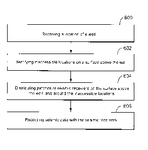
[0044] According to an embodiment illustrated in Figure 6, there is a
method for monitoring microseismic events taking place in a subsurface, below
a
surface of the earth. The method includes a step 600 of receiving a location
of a
well, a step 602 of identifying inaccessible locations on a surface above the
well,
12
CA 02824208 2013-08-22
CG200042
a step 604 of distributing patches of seismic receivers on the surface above
the
well and around the inaccessible locations, and a step 606 of recording
seismic
data with the seismic receivers.
[0045] Another method for processing seismic data associated with
microseismic events taking place in a subsurface, below a surface of the
earth,
may include a step of receiving, at plural receivers, the seismic data
associated
with the microseismic events, sending the seismic data from the plural
receivers
to a patch processing device, partially processing the seismic data at the
patch
processing device, sending the partially processed seismic data from the patch
processing device to a central processing device, and further processing the
partially processed seismic data at the central processing device to generate
an
image of the subsurface. The seismic data is transmitted between the receivers
and the patch processing device and between the patch processing device and
the central processing device by one of the following paths: wireless, wired,
and
a combination of wired and wireless. The step of partially processing the
seismic
data may include a step of pre-processing the seismic data, e.g., denoising, a
step of applying time-shifts, a summation step, etc.
[0046] An area on which the receivers are distributed may be computed as
now discussed. A depth of a well is multiplied with a number p to obtain a
first
distance D1; the depth of the well is also multiplied with a number r to
obtain a
second distance D2. A circle having a diameter equal to twice D1 or equal to
D2
is generated and this circle is the area in which the receivers are to be
distributed. For this area, p is 2 or smaller and r is 4 or smaller. Instead
of a
circle, a square having a side equal to twice D1 or D2 may be generated, where
p is 2 or smaller and r is 4 or smaller. In another application, a rectangle
may be
generated having a first side equal to twice D1 and a second side equal to D2,
with p being 2 or smaller and r being 4 or smaller. In still another
application, the
13
CA 02824208 2013-08-22
CG200042
patches are distributed at vertices of hexagons covering the area and/or
additional patches are distributed at centers of the hexagons.
[0047] The methods discussed above may be implemented in dedicated
devices (e.g., dedicated networks or computers or cloud computing networks,
etc.) for being performed. A combination of software and hardware may be used
to implement the above-described methods. A dedicated machine that can
implement one or more of the above-discussed exemplary embodiments is now
discussed with reference to Figure 7.
[0048] An exemplary computing arrangement 700 suitable for performing
the activities described in the exemplary embodiments may include server 701.
Such a server 701 may include a central processor (CPU) 702 coupled to a
random access memory (RAM) 704 and to a read-only memory (ROM) 706.
ROM 706 may also be other types of storage media to store programs, such as
programmable ROM (PROM), erasable PROM (EPROM), etc. Processor 702
may communicate with other internal and external components through
input/output (I/0) circuitry 708 and bussing 710, to provide control signals
and the
like. Processor 702 carries out a variety of functions as is known in the art,
as
dictated by software and/or firmware instructions.
[0049] Server 701 may also include one or more data storage devices,
including hard disk drives 712, CD-ROM drives 714, and other hardware capable
of reading and/or storing information such as DVD, etc. In one embodiment,
software for carrying out the above-discussed steps may be stored and
distributed on a CD-ROM 716, diskette 718 or other form of media capable of
portably storing information. These storage media may be inserted into, and
read by, devices such as CD-ROM drive 714, disk drive 712, etc. Server 701
may be coupled to a display 720, which may be any type of known display or
presentation screen, such as LCD, plasma display, cathode ray tubes (CRT),
etc.
A user input interface 722 is provided, including one or more user interface
14
CA 02824208 2013-08-22
CG200042
mechanisms such as a mouse, keyboard, microphone, touch pad, touch screen,
voice-recognition system, etc.
[0050] Server 701 may be coupled to other computing devices, such as
the landline and/or wireless terminals via a network. The server may be part
of a
larger network configuration as in a global area network (GAN) such as the
Internet 728, which allows ultimate connection to the various landline and/or
mobile clients.
[0051] As also will be appreciated by one skilled in the art, the
exemplary
embodiments may be embodied in a wireless communication device, a computer
network, as a method or in a computer program product. Accordingly, the
exemplary embodiments may take the form of an entirely hardware embodiment or
an embodiment combining hardware and software aspects. Further, the exemplary
embodiments may take the form of a computer program product stored on a
computer-readable storage medium having computer-readable instructions
embodied in the medium. Any suitable computer readable medium may be utilized,
including hard disks, CD-ROMs, digital versatile disc (DVD), optical storage
devices, or magnetic storage devices such a floppy disk or magnetic tape.
Other
non-limiting examples of computer-readable media include flash-type memories
or
other known memories.
[0052] The disclosed exemplary embodiments provide a system and a
method for using patches of receivers in microseismic detection. It should be
understood that this description is not intended to limit the invention. On
the
contrary, the exemplary embodiments are intended to cover alternatives,
modifications and equivalents, which are included in the spirit and scope of
the
invention as defined by the appended claims. Further, in the detailed
description
of the exemplary embodiments, numerous specific details are set forth in order
to
provide a comprehensive understanding of the claimed invention. However, one
CA 02824208 2013-08-22
CG200042
skilled in the art would understand that various embodiments may be practiced
without such specific details.
[0053] Although the features and elements of the present exemplary
embodiments are described in the embodiments in particular combinations, each
feature or element can be used alone without the other features and elements
of
the embodiments or in various combinations with or without other features and
elements disclosed herein.
[0054] This written description uses examples of the subject matter
disclosed to enable any person skilled in the art to practice the same,
including
making and using any devices or systems and performing any incorporated
methods. The patentable scope of the subject matter is defined by the claims,
and
may include other examples that occur to those skilled in the art. Such other
examples are intended to be within the scope of the claims.
16