Note : Les descriptions sont présentées dans la langue officielle dans laquelle elles ont été soumises.
"FLEXIBLE SKID STEER ATTACHMENT DEVICE"
Cross-Reference to Related Applications
[001] None
Field of Invention
[002] The present invention relates to the field of road apparatuses, and more
particularly to a flexible skid steer attachment device for paving shoulders
and widening
roads.
Brief Description of the Drawings
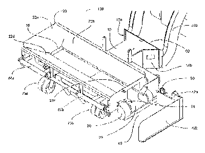
[003] FIG. 1 illustrates a front perspective view of an exemplary embodiment
of
a flexible skid steer road widening and shouldering attachment device attached
to a skid
steer with spreader system extended.
[004] FIG. 2a illustrates a back perspective view of an exemplary embodiment
of a flexible skid steer road widening and shouldering attachment device
attached to a
skid steer.
[005] FIG. 2b illustrates a back perspective view of an exemplary embodiment
of a flexible skid steer road widening and shouldering attachment device
attached to a
skid steer with spreader system extended.
[006] FIG. 3 illustrates a back perspective view of an exemplary embodiment
of a flexible skid steer road widening and shouldering attachment device
attached to a
skid steer and positioned behind a truck.
1
CA 2824966 2017-08-16
[007] FIG. 4 is a side view showing the spreader system of an exemplary
embodiment of a flexible skid steer road widening and shouldering attachment
device
attached to a skid steer and positioned behind a truck.
[008] FIG. 5 is a side view of an exemplary embodiment of a flexible skid
steer
road widening and shouldering attachment device attached to a skid steer and
positioned behind a truck.
[009] FIG. 6 is a top view of an exemplary embodiment of a flexible skid steer
road widening and shouldering attachment device attached to a skid steer and
positioned behind a truck.
Background
[010] After-market attachments for road widening and shouldering are well-
known in the construction industry.
[011] U.S. Pat. No. 7,540,687 (Neumann '687) teaches a skid steer
attachment for performing work in confined areas (e.g., road shoulders,
trenches). The
attachment disclosed in Neumann '687 is comprised of a compact frame adapted
to
support a hopper; a conveyer system; a spreader system; a spreader system
angular
adjustment; a hydraulic system; wheels; front contact rollers, which contact
the back
wheels of a dump truck; and a universal mounting plate. This device has
enjoyed an
extensive market presence and improvements have been made to further increase
its
utility and durability.
[012] A limitation of Neumann '687 was that the conveyer belt system would
become misaligned due to the pressure from debris coming in contact with the
belt over
2
CA 2824966 2017-08-16
time, as well as from the motion of the vehicle. The conveyer belt was
required to be
realigned by running the hydraulics and lifting, then realigning, the flashing
between the
hopper and conveyer belt. The belt would then realign itself.
[013] A further limitation of the device disclosed in Neumann '687 is that it
has to
be disassembled before being placed on a trailer. The front rollers of the
device have to
be manually removed, causing time delays for disassembly and reassembly.
[014] The hopper further includes an additional wall which is secured to the
hopper on the side opposite the spreader system.
[015] The skid steer attachment disclosed by Neumann '687 has enjoyed a wide
market, and experience with the device has led to improvements resulting in a
highly
resilient and more portable attachment as disclosed herein.
Summary of the Invention
[016] The present invention is a flexible skid steer road widening and
shouldering attachment device with an adjustable spreader system which gives
the
operator precise control over the placement of debris. The flexible skid steer
road
widening and shouldering attachment device disclosed herein is an improved
version of
the attachment disclosed by U.S. Pat. No. 7,540,687 (Neumann '687). The
present
invention is comprised of improved support components, an improved hopper
design
that optimizes the angle of deflection for debris, design dimensions and
reduced sized
rollers that eliminate the need for disassembly of the device for transport, a
hopper
deflection component, and a shortened flap design. Additionally, two tandem
casters
3
CA 2824966 2017-08-16
CA 2824966 2017-05-17
are used to more equally distribute the weight of the apparatus reducing the
number of
casters needed.
[0 I 6a] In accordance with an aspect of the present invention, there is
provided
a highly resilient skid steer attachment for a skid steer comprised of:
a support frame supported by at least two support brackets configured to
distribute a load over the support frame;
a hopper having a plurality of angled walls for receiving debris at an angle
of
deflection which minimizes the impact of debris on a conveyer belt, wherein at
least one
of the plurality of angled walls further includes a vertical deflection
component for
directing debris downward;
a conveyor system comprised of a conveyer belt and a pulley, said pulley
being at least two inches wider than said conveyer belt;
at least one hydraulic system for powering said conveyor system;
a spreader system;
a plurality of tandem casters rotatably attached at a first end of said
support frame;
at least one contact roller rotatably attached to said first end of said
support frame
configured for engagement with a set of rear wheels of a truck; and a
universal mounting
plate attached at a second end of the support frame in a manner that allows
said mounting
plate to be engaged by a skid steer when the contact rollers arc engaged with
the rear
wheels of a truck as the truck delivers the debris to the hopper.
[016b) In accordance with a further aspect of the present invention, there is
provided a portable skid steer attachment for a skid steer comprised of:
a support frame supported by at least two support brackets;
a hopper with a plurality of angled walls for receiving debris at an angle of
deflection which minimizes the impact of debris on a conveyer belt, wherein at
least one
of the plurality of angled walls further includes a vertical deflection
component for
directing debris downward;
4
CA 2824966 2017-05-17
a conveyor system comprised of a conveyer bat and a pulley, said pulley being
at least two inches wider than said conveyer belt;
at least one hydraulic system for powering said conveyor system;
a first spreader system and spreader system angular adjustment, the first
spreader
system comprising a first wall extending at a first angle from the support
frame and a
second wall extending at a second angle from the first wall;
a plurality of tandem casters rotatably attached at a first end of said
support frame,
said casters protruding no more than 14 inches from the frame;
at least one contact roller rotatably attached to said first end of said
support frame
configured for engagement with at least one rear wheel of a vehicle as the
vehicle
delivers the debris to the hopper; and
a universal mounting plate attached at a second end of the support frame in a
manner that allows said mounting plate to he engaged by a skid steer.
[016e] In accordance with a further aspect of the present invention, there is
provided a highly resilient skid steer attachment for a skid steer comprised
of:
a support frame supported by at least two support brackets;
a hopper having four angled walls for receiving debris at an angle of
deflection
which minimizes the impact of debris On a conveyer belt;
wherein one of said four angled walls is vertical relative to a horizontal
plane;
wherein three of said four angled walls further include a vertical deflection
component for directing debris downward;
a conveyer system comprised of a conveyer belt and a pulley, said pulley being
at
least two inches wider than said conveyer belt;
at least one hydraulic system for powering said conveyer system;
a spreader system;
a plurality of tandem casters rotatably attached at a first end of said
support frame;
at least one contact roller rotatably attached to said first end of said
support frame;
CA 2824966 2017-05-17
and
a universal mounting plate attached at a second end of the support frame in a
manner that allows said mounting plate to be engaged by a skid steer when the
contact
rollers are engaged with the rear wheels of a truck as the truck delivers the
debris to the
hopper.
Detailed Description of invention
[0017] For the purpose of promoting an understanding of the present invention,
references are made in the text to exemplary embodiments of a flexible skid
steer road
widening and shouldering attachment device, only some of which are described
herein. It
should be understood that no limitations on the scope of the invention are
intended by
describing these exemplary embodiments. One of ordinary skill in the art will
readily
appreciate that alternate but functionally equivalent components, component
placement,
materials, and dimensions may be used. The inclusion of additional elements
may be
deemed readily apparent and obvious to one of ordinary skill in the art.
Specific elements
disclosed herein are not to be interpreted as limiting, but rather as a basis
for the claims
and as a representative basis for teaching one of ordinary skill in the art to
employ the
present invention.
[0018] It should be understood that the drawings arc not necessarily to scale;
instead, emphasis has been placed upon illustrating the principles of the
invention. In
addition, in the embodiments depicted herein, like reference numerals in the
various
drawings refer to identical or near identical structural elements.
[0019] Moreover, the terms "substantially" or "approximately" as used herein
may be applied to modify any quantitative representation that could
permissibly vary
without resulting in a change in the basic function to which it is related.
4b
[020] FIG. 1 illustrates a front perspective view of an exemplary embodiment
of
flexible skid steer road widening and shouldering attachment device 100
attached to
skid steer 200. Attachment device 100 is comprised of support frame 10 adapted
to
support hopper 20, conveyer system 30, spreader system 40, hydraulic system 50
(not
visible) and universal mounting plate 60.
[021] In the embodiment shown, support frame 10 further includes support
brackets 15a, 15b which add additional structural support to support frame 10.
Support
brackets 15a, 15b reinforce support frame 10 preventing universal mounting
plate 60
from cracking where welded to support frame 10. Support bracket 15b may also
serve
as a step to aid the user in climbing into skid steer 200.
[022] In the embodiment shown, support brackets 15a, 15b provide a more
equal weight distribution and larger surface area on which to distribute the
weight of
support frame 10 than a mounting plate alone.
[023] Hopper 20 is comprised of walls 22a, 22b, 22c, 22d angled inward to
facilitate the movement of debris (e.g., gravel) onto conveyer system 30 which
makes
up the bottom of hopper 20. Conveyer system 30 moves debris away from wall 22a
of
hopper 20 and toward spreader system 40. In the embodiment shown, conveyer
system 30 is comprised of conveyer belt 35 and a plurality of rollers that are
horizontally
aligned beneath the lower opening of hopper 20.
[024] In the embodiment shown, walls 22a, 22b, 22d of hopper 20 are gently
angled toward conveyer belt 35 which slows the speed and force at which debris
is
pushed onto conveyer belt 35 decreasing the chance that the weight of the
debris will
force conveyer belt 35 off its rollers.
CA 2824966 2017-08-16
[025] In an exemplary embodiment, wall 22c is substantially vertical relative
to
conveyer belt 35 (at an approximate 90 degree angle) to facilitate attachment
of hopper
20 to support frame 10. Walls 22b, 22a and 22d are all placed at varying
angles
ranging from 100 to 170 degrees (as measured from a point on a horizontal
plane inside
hopper 20) to deflect debris onto conveyer belt 35.
[026] FIG. 1 also illustrates vertical drop component 18 which deflects debris
from walls 22a, 22b, 22d vertically onto conveyer belt 35, rather than
laterally, so as not
to cause pressure on the conveyer belt 35 leading to misalignment over time.
[027] In the embodiment shown, conveyer belt 35 further includes a pulley that
is at least 2 inches wider than conveyer belt 35 to prevent conveyer belt 35
from moving
off the edge of the pulley. This design modification substantially decreases
delay
resulting from malfunction.
[028] In other embodiments, conveyer system 30 may be replaced with another
means for moving debris from hopper 20 out toward spreader system 40. For
example,
chains may be used to displace debris from hopper 20. Conveyer belt 35 may be
any
functionally equivalent apparatus known in the art including, but not limited
to a chain
conveyer, screw conveyer, and any pneumatic, flexible, and vibrating system.
[029] In the embodiment shown, attachment device 100 is approximately 125
inches wide, approximately 97 inches long, and approximately 32 inches high
(top of
hopper 20). The dimensions of attachment device 100 allow it to be pulled by a
pick-up
truck or transported by any common-width vehicle, avoiding the need for
disassembly or
a specialty width vehicle. In addition, attachment device 100 does not require
an over-
width permit for transportation or operation. In various embodiments,
attachment device
6
CA 2824966 2017-08-16
100 has a width ranging from 100 inches to 170 inches, a length ranging from
75 inches
to 175 inches and a height ranging from 28 inches to 58 inches.
[030] In the embodiment shown, spreader system 40 is extended. Spreader
system 40 is comprised of two walls 42a, 42b which are formed at a right
angle. When
spreader system 40 is extended, conveyer system 30 carries debris out of
hopper 20.
As skid steer 200 pushes attachment device 100, spreader system 40 spreads the
debris dropped into hopper 20 by truck 300 (not shown). In the embodiment
shown,
spreader system 40 can be extended to disperse debris over widths of 0 to 7
feet. In
one embodiment, spreader system 40 can create a shoulder ranging from 0 to 4
feet 6
inches.
[031] In other embodiments, attachment device 100 includes two spreader
systems, one located on each side of attachment device 100.
[032] Also visible are casters 75a, 75b which are secured to the bottom of
attachment device 100 aiding in the movement and maneuverability of attachment
device 100 when shouldering around obstacles (e.g., mailboxes, driveway
approaches,
street signs, intersections, cul-du-sacs, guard rails). In the embodiment
shown, casters
75a, 75b are comprised of steel polyurethane plastic and are solidly
constructed (i.e.,
having no air cavity). It has been demonstrated that this construction is
superior in
performance to air-filled casters because of the added strength and durability
to support
the weight.
[033] In the embodiment shown, casters 75a, 75b are attached to a plate on the
bottom of the first end of attachment device100 and protrude no more than 14
inches
past the frame of attachment device 100.
7
CA 2824966 2017-08-16
[034] In the embodiment shown, attachment device 100 further includes front
rollers 80a, 80b which contact the back tires of truck 300 when attachment
device 100 is
receiving debris from the bed of truck 300.
[035] FIG. 2a illustrates a back perspective view of an exemplary embodiment
of flexible skid steer road widening and shouldering attachment device 100
attached to
skid steer 200 with spreader system 40 in a partially open position. Visible
is hydraulic
system 50 which extends and closes spreader system 40. Hydraulic system 50 is
also
used to drive conveyer system 40.
[036] Attachment device 100 further includes tie downs 70a, 70b, 70c, 70d (70d
not visible) for securing attachment device100 during transport. In various
embodiments, attachment device 100 may include a smaller or greater number of
tie-
downs in varying locations or similar components which can be used to secure
attachment device 100 during transport.
[037] In the embodiment shown, skid steer 200 may be used to lift and tilt
hopper 20 to place debris in front of attachment device 100.
[038] FIG. 2b illustrates a back perspective view of an exemplary embodiment
of flexible skid steer road widening and shouldering attachment device 100
attached to
skid steer 200 with spreader system 40 extended. The slope of spreader system
40
may be adjusted to create the desired shouldering angle.
[039] FIG. 3 illustrates a back perspective view of an exemplary embodiment of
flexible skid steer road widening and shouldering attachment device 100
attached to
skid steer 200 and positioned behind truck 300. Skid steer 200 pushes
attachment
device 100 against truck 300 as truck 300 moves forward. Truck 300 dumps
debris
8
CA 2824966 2017-08-16
directly into hopper 20 of attachment device. Conveyer system 30 moves the
debris
from hopper 20 out to spreader system 40. As attachment device 100 moves,
spreader
system 40 spreads the debris allowing precise control over the placement of
the debris.
[040] In the embodiment shown, truck 300, attachment device 100 and skid
steer 200 is capable of dispersing a 20-ton truckload of gravel in minutes
resulting in a
perfect shoulder.
[041] FIG. 4 is a side view showing spreader system 40 of an exemplary
embodiment of flexible skid steer road widening and shouldering attachment
device 100
attached to skid steer 200 and positioned behind truck 300.
[042] FIG. 5 is a side view of an exemplary embodiment of flexible skid steer
road widening and shouldering attachment device 100 attached to skid steer 200
and
positioned behind truck 300.
[043] FIG. 6 is a top view of an exemplary embodiment of flexible skid steer
road widening and shouldering attachment device100 attached to skid steer 200
and
positioned behind truck 300.
9
CA 2824966 2017-08-16