Note : Les descriptions sont présentées dans la langue officielle dans laquelle elles ont été soumises.
CA 02825661 2013-07-22
WO 2012/099594
PCT/US2011/021962
TEMPERATURE SENSING SOOTBLOWER
BACKGROUND
The entrainment of fly ash particles from the lower furnace of an industrial
boiler to the convection sections of the boiler is an inevitable process. The
accumulation of these particles in the fireside heat exchanger surfaces
reduces the
boiler thermal efficiency, creates a potentially corrosive environment at the
boiler tube
surfaces and, if the accumulation is not properly controlled, may also lead to
costly
unscheduled boiler shutdowns due to plugging of the gas passages.
Knowledge of the flue gas temperatures across the boiler heat transfer
surfaces is therefore an important piece of information that can be used to
evaluate
fireside deposit characteristics, to improve boiler cleaning operation through
intelligent deposit removal processes, and to optimize boiler operation and
combustion processes. Conventional temperature sensors positioned in fixed
locations on boiler walls or other internal boiler structures do not monitor
flue gas
temperatures across the boiler heat transfer surfaces. There is, therefore, a
continuing need for effective ways of monitoring the internal temperature of
flue
gasses across heat transfer surfaces inside of industrial boilers.
Sootblowers are by far the most widely used equipment to remove the fireside
deposit accumulations in industrial boilers, such as oil-fired, coal-fired,
trash-fired,
waste incinerator, as well as boilers used in paper manufacturing, oil
refining, steel,
and aluminum smelting and other industrial enterprises. A sootblower consists
of a
lance tube with one or more nozzles. During the deposit removal process, the
sootblower lance rotates and extends through a small opening in the boiler
wall, while
blowing high pressure cleaning fluid (e.g., steam, air or water) directed into
the tube
banks. After the lance is fully extended, it rotates in the opposite direction
as it
retracts to its original inactive state.
The sootblower carriage consists of one or two electric motor(s), a gearbox
and a packing housing. The electric motor is the main drive that moves the
lance
tube forward and backward during the cleaning cycle. The motor converts
electrical
energy into rotation motion, which is then used by the gearbox to rotate and
move the
lance tube along the gear rack. As the steam enters a sootblower, it is
directed to
four components in the following order: poppet valve, feed tube, lance tube,
and
1
SUBSTITUTE SHEET (RULE 26)
CA 02825661 2013-07-22
WO 2012/099594
PCT/US2011/021962
nozzles. The lance tube is the main component that travels within the boiler
while
supplying the sootblower nozzles with high pressure steam directed by jets
toward
the boiler tubes. The lance travel includes insertion into and retraction from
the
boiler. During the cleaning process, the lance extends into the boiler and
forms a
structure similar to a cantilevered beam. Hence, the lance has to be designed
to
have sufficient strength to support its own weight in a high temperature
environment.
To avoid overheating the lance tube during internal boiler operation, the
blowing fluid, which also acts as a cooling medium, needs to be supplied
continuously
to the lance. The minimum amount of the cleaning media required to prevent the
lance from overheating is known as the minimum cooling flow. The minimum
cooling
flow of a lance tube depends on the material, the length of the lance tube,
the steam
and flue gas temperatures. Knowledge of the lance tube temperatures as the
lance is
being exposed to hot flue gas inside the boiler is very important to prevent
lance tube
overheating and to devise emergency sootblower retraction control strategy. A
continuing need therefore exists for effective ways for monitoring the
temperature of
the lance tube as the lance is exposed to hot flue gas inside the boiler.
SUMMARY OF THE INVENTION
The present invention meets the needs described above in a temperature
sensing sootblower that includes an elongated lance tube configured to travel
adjacent to and across a heat transfer surface in a boiler while directing a
cleaning
fluid through one or more nozzles toward the heat transfer surface to remove
fireside
deposits from the heat transfer surface. The lance tube carries a temperature
sensor
that is configured to obtain temperature measurements of the flue gas within
the
boiler, lance tube, and/or cleaning fluid while the lance is located within
the boiler. A
boiler cleaning controller may control boiler cleaning operations based on the
temperature measurements. A data acquisition unit typically receives and
records
the temperature measurements from the temperature sensor and transmits the
temperature measurements to the boiler cleaning controller.
The temperature sensing sootblower also includes a data transfer device that
transfers the temperature measurements from the temperature sensor to the data
acquisition unit while the temperature sensor rotates with the lance tube.
In
particular, the data transfer device may be a slip ring fixed to the lance
tube.
2
SUBSTITUTE SHEET (RULE 26)
CA 02825661 2013-07-22
WO 2012/099594
PCT/US2011/021962
To measure the temperature of the flue gas as opposed to the lance tube and
avoid the cooling effect of the cleaning fluid on the flue gas, the
temperature sensing
sootblower may include a lance tube extension supporting the temperature
sensor
beyond a leading end of the lance tube in an insertion direction of the lance
tube.
The lance tube extension may also support the temperature sensor beyond the
lance
tube extension in the insertion direction.
The temperature sensing sootblower may include a groove in the lance tube
and the temperature sensor may be a thermocouple positioned within the grove.
A
welding rod may be positioned above the thermocouple within the grove with an
overlay weld positioned above the welding rod sealing the thermocouple within
the
grove.
The invention may also be practiced as a temperature sensing sootblower that
includes an elongated lance tube and a temperature sensor carried by the lance
tube
configured to obtain temperature measurements of the lance tube while the
lance
tube travels within the boiler. The flue gas temperature sensor and the lance
tube
temperature sensor may also be combined, such that the lance tube carries a
first
temperature sensor configured to obtain temperature measurements of flue gas
within
the boiler across the heat transfer surface as the lance tube travels across
the heat
transfer surface and a second temperature sensor configured to obtain
temperature
measurements of the lance tube while the lance tube travels within the boiler.
In this
case, the temperature sensors may be a pair of thermocouples located in a
stranded
wire positioned within the grove. Multiple temperature sensors also may be
located
along the lance tube if desired.
In addition, the temperature sensing sootblower may also include a
thermocouple in contact with the lance tube for measuring the temperature of
the
lance tube and/or a thermocouple extending through a hole in the lance tube
into an
interior of the lance tube for measuring the temperature of a cleaning fluid
inside the
lance tube. The boiler cleaning controller may be configured to retract the
lance tube
in response to temperature measurements from the temperature sensor indicating
that the lance tube has exceeded a predetermined temperature.
In view of the foregoing, it will be appreciated that the present invention
avoids
the drawbacks of prior boiler temperature measuring systems and provides an
improved temperature sensing sootblower. The specific techniques and
structures
for creating the temperature sensing sootblowers, and thereby accomplishing
the
3
SUBSTITUTE SHEET (RULE 26)
CA 02825661 2016-02-22
advantages described above, will become apparent from the following detailed
description
of the embodiments and the appended drawings and claims.
In a broad aspect, the invention pertains to a temperature sensing sootblower,
comprising an elongated lance tube configured to travel within a boiler while
directing
a cleaning fluid through one or more nozzles toward the heat transfer surface
to remove
fireside deposits from the heat transfer surface, a temperature sensor carried
by the lance
tube within the boiler configured to obtain temperature measurements of flue
gas within
the boiler while the lance tube is located within the boiler, and a lance tube
extension
supporting the temperature sensor beyond a leading end of the lance tube in an
insertion
direction of the lance tube.
In a further aspect, the invention provides a temperature sensing sootblower,
comprising an elongated lance tube configured to travel within a boiler while
directing
a cleaning fluid through one or more nozzles toward a heat transfer surface to
remove
fireside deposits from the heat transfer surface, a first temperature sensor
carried by the
lance tube within the boiler configured to obtain temperature measurements of
the lance
tube while the lance tube is located within the boiler, and a second
temperature sensor
carried by the lance tube within the boiler is configured to obtain
temperature
measurements of flue gas within the boiler while the lance tube is located
within the
boiler. The second temperature sensor is supported by the lance tube extension
beyond
a leading edge of the lance tube in an insertion direction of the lance tube.
4
CA 02825661 2016-02-22
In a still further aspect, the invention provides a temperature sensing
sootblower.
There is an elongated lance tube configured to travel within a boiler while
directing a
cleaning fluid through one or more nozzles toward a heat transfer surface to
remove
fireside deposits from the heat transfer surface. A first temperature sensor
extends
through a hole in the lance tube into an interior of the lance tube for
measuring the
temperature of a cleaning fluid inside the lance tube while the lance tube is
located within
the boiler. A second temperature sensor is carried by the lance tube within
the boiler
configured to obtain temperature measurements of flue gas within the boiler
while the
lance tube is located within the boiler. The second temperature sensor is
supported by
the lance tube extension beyond a leading edge of the lance tube in an
insertion direction
of the lance tube.
4a
CA 02825661 2013-07-22
WO 2012/099594
PCT/US2011/021962
BRIEF DESCRIPTION OF THE FIGURES
FIG. 1 is a schematic illustration of a temperature sensing sootblower.
FIG. 2 is a conceptual illustration of the temperature sensing sootblower
measuring the temperature of flue gas across a heat transfer surface in a
boiler.
FIG. 3 is a side view of a temperature sensing sootblower showing the location
of the slip ring data transfer device.
FIG. 4 is a perspective view of a temperature sensing sootblower lance.
FIG. 5 is an enlarged view of Detail A of FIG. 7 showing the end of the
temperature sensing sootblower lance.
FIG. 6 is an end view of the temperature sensing sootblower lance.
FIG. 7 is an enlarged view of Detail B of FIG. 6 showing the thermocouple
temperature sensor, protective welding wire, and overlay weld.
FIG. 8 is a further enlargement of the groove in the temperature sensing
sootblower carrying the thermocouple temperature sensor, protective welding
wire,
and overlay weld.
FIG. 9 is a cut away view of the end of the temperature sensing lance tube
showing the boiler gas monitoring location and the end of the unmodified lance
tube.
FIG. 10 is a conceptual cross sectional side view of a sootblower lance
carrying a temperature sensor for measuring the temperature of the cleaning
fluid
inside the lance.
FIG. 11 is a logic flow diagram illustrating a routine for activating a boiler
cleaning operation in response to flue gas temperatures measured with the
temperature sensing sootblower.
FIG. 12 is a logic flow diagram illustrating a routine for activating a boiler
cleaning operation in response to differential flue gas temperatures across a
heat
transfer surface measured with the temperature sensing sootblower.
FIG. 13 is a logic flow diagram illustrating a routine for controlling a
boiler
cleaning operation based on temperature profile testing.
FIG. 14 is a logic flow diagram illustrating a routine for protecting the
temperature sensing sootblower to avoid a potential overheating condition.
DETAILED DESCRIPTION OF THE PREFERED EMBODIMENTS
This invention can be embodied in a temperature sensing sootblower that may
be configured as a modification to an existing sootblower or a specially
constructed
5
SUBSTITUTE SHEET (RULE 26)
CA 02825661 2013-07-22
WO 2012/099594
PCT/US2011/021962
sootblower that, in addition to its normal soot blowing functions, has the
capability to
measure the flue gas, lance tube, and/or cleaning fluid temperatures. One or
more
thermocouples or other temperature measuring devices are carried by the
sootblower
lance tube that travels within the boiler. This allows for the temperature of
the flue
gas, lance tube, and/or cleaning fluid to be measured as the sootblower lance
tube is
inserted into and retracted from the boiler. Multiple temperature measuring
devices
may be located on the sootblower lance to measure the temperature across heat
transfer surfaces and at different locations along the lance tube. A data
transfer
device transmits the temperature measurements from the rotating thermocouple
to a
non-rotating data acquisition unit for use in boiler cleaning and other
operations.
A data transfer device, such as a slip ring, is used to transfer the signal
from
the thermocouple to a data acquisition unit located on the non-rotating part
of the
sootblower. The invention may also be used in sootblowers that are partially
inserted
in the boiler (sometimes called half-track sootblowers). It may also be used
in
sootblowers that are continually inserted into the boiler gas path. The
temperature
sensor may be a thermocouple, a Resistance Temperature Detector (RTD), or
other
suitable type of sensing device that is attached to the lance tube of the
sootblower.
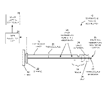
FIG. 1 is a schematic illustration of the temperature sensing sootblower 10
including the lance tube 12 extending from a flange 16 that supports one end
of the
lance tube to the nozzles 14. The lance tube is inserted through a hole in the
boiler
wall into interior of the boiler, where it is extended and retracted to clean
heat transfer
surfaces inside the boiler. The nozzle(s) can be installed anywhere in the
lance tube
where one or more cleaning fluids, such as steam, air or water, are supplied
to the
nozzle(s) to clean the fireside deposits from internal boiler heat transfer
surfaces.
The lance tube rotates as it travels in the insertion direction (from flange
toward the
tip of the lance), blowing a spiral of cleaning fluid as is travels across an
adjacent
heat transfer surface. The lance tube rotates in the opposite direction (from
the tip of
the lance toward flange) as it travels in the retraction direction.
To measure the temperature of the flue gas and the lance tube inside the
boiler, the temperature sensing sootblower 10 carries temperature sensors, in
this
illustration a multi strand thermocouple 20 that extends longitudinally along
the lance
tube. The thermocouple is connected to a data transfer device, in this
illustration a
slip ring 22 that transfers the temperature measurements from the thermocouple
to a
data acquisition unit 24 while the thermocouple rotates with the lance tube.
The data
6
SUBSTITUTE SHEET (RULE 26)
CA 02825661 2013-07-22
WO 2012/099594
PCT/US2011/021962
acquisition unit 24, in turn, transmits the temperature measurements to a
boiler
cleaning controller 25 or other processor that may use the measurements for a
variety
of purposes, such as displaying the temperature profile across heat transfer
surfaces
inside the boiler, activating sootblowers and other boiler cleaning equipment,
adjusting boiler operation, retracting the lance tube to prevent overheating,
and so
forth. As the data acquisition unit 24 includes a processor, it may create
temperature
and perform some of these functions.
The thermocouple 20 is typically a stranded wire containing a number of two-
wire thermocouples allowing for multiple temperature sensing locations 26
along the
lance tube. For example, the thermocouple may include six wires providing
three
Type K thermocouples. This provides knowledge of the lance tube temperature so
that the lance tube can be retracted to prevent overheating. The temperature
along
the lance tube may be monitored at multiple locations, as desired.
The thermocouple may also include a boiler gas monitoring location 30
positioned beyond the tip of the lance in the lance insertion direction. To
obtain the
temperature of the boiler flue gas rather than the lance tube, a lance tube
extension
28 supports the thermocouple beyond the tip of the lance in the lance
insertion
direction. The thermocouple also extends a bit beyond the lance tube extension
28
so that the temperature monitoring location 30 is supported in the flue gas
without
physically touching the lance tube extension. For example, the lance tube
extension
28 may extend four to six inches beyond the tip of the lance and the
thermocouple 20
may extend another half inch to the boiler gas monitoring location 30. The
lance tube
extension 28 may also include one or more vents 34 to for cooling purposes.
The
lance tube extension is typically made from the same type of material as the
lance
tube and welded onto the tip of the lance.
FIG. 2 is a conceptual illustration of the temperature sensing sootblower 10
measuring the temperature of flue gas across a heat transfer surface 32 in a
boiler.
The boiler gas temperature monitoring location 30 of the thermocouple 20
measures
the temperature of the flue gas as the sootblower lance 12 travels adjacent to
and
across the heat transfer surface 32. The data acquisition unit 24, the boiler
cleaning
controller 25, or another processor creates a profile of the internal
temperature of the
boiler across the heat transfer surface. The temperature profile generally
indicates
whether the heat transfer surface is carrying fireside deposits reducing the
heat
transfer capability of the heat transfer surface, allowing for intelligent
boiler operation
7
SUBSTITUTE SHEET (RULE 26)
CA 02825661 2013-07-22
WO 2012/099594
PCT/US2011/021962
including intelligent sootblower operation. The temperature monitoring
location(s) 26
also measure the temperature of the lance tube allowing the lance tube to be
retracted to prevent overheating.
FIGS. 3-7 show an illustrative embodiment of the temperature sensing
sootblower substantially to scale. FIG. 3 is a side view of the temperature
sensing
sootblower 10 indicating the location of the slip ring data transfer device 22
and the
flange 16. The slip ring is typically mounted to a non-rotating plate
positioned about
six inches ahead of the flange 16 to prevent damage to the slip ring in the
event of a
steam leak from the flange. The slip ring includes a ball bearing or similar
race with
an inner sleeve that rotates with the lance tube and a non-rotating outer
sleeve fixed
to the plate. Wires connected to the inner sleeve are connected to the
thermocouple
while wires connected to the outer sleeve are connected to the data
acquisition unit.
This allows the slip ring to transmit the temperature measurements from the
rotating
thermocouple to the non-rotating data transfer unit. Another type of data
transfer
device may be used, however, such as a wireless data link between the
thermocouple
and the data acquisition unit or any other suitable type of data transfer
device.
FIG. 4 is a perspective view of the tip of the lance portion of the
temperature
sensing sootblower lance 12 with the groove 40. FIG. 5 is an enlarged view of
Detail
A of FIG. 4 showing the end of the temperature sensing sootblower lance
including
the lance tube extension 28. FIG 6 is an end view of the temperature sensing
sootblower lance 12 and FIG. 8 is an enlarged view of a Detail B of FIG. 7
showing
the groove 40. FIG. 8 is a further enlargement of the groove 40 carrying the
thermocouple 20, the protective welding wire 42, and the overlay weld 44. The
groove, which extends from the slip ring to the end of the lance tube
extension, may
be machined or cut into the lance tube with saw. The thermocouple 20 is
positioned
at the bottom of the groove 40 with the protective welding wire 42 positioned
above
the thermocouple. An overlay weld 44 is welded over the grove to seal the
thermocouple in the groove. The protective welding wire prevents the
thermocouple
from being damaged during the welding process. The groove 44 is cut
approximately
the same size as the protective welding wire to provide a snug interference
fit
between the groove and the welding wire. The thermocouple may be the same size
or a smaller than the welding wire.
FIG. 9 is an enlarged cut-away view of the end of the temperature sensing
sootblower lance tube 12 showing the boiler gas temperature monitoring
location 30
8
SUBSTITUTE SHEET (RULE 26)
CA 02825661 2013-07-22
WO 2012/099594
PCT/US2011/021962
at the end of the thermocouple extending beyond the end of the lance tube
extension
28. FIG. 9 also shows the rounded end 60 of the unmodified lance tube.
In view of the foregoing, it will be appreciated that present invention
provides
significant improvements in sootblowers and boiler temperature monitoring
systems
and that numerous changes may be made therein without departing from the
spirit
and scope of the invention as defined by the following claims.
FIG. 10 is a conceptual cross sectional side view of a wall 11 of the
sootblower
lance 12 carrying a multi-strand thermocouple 20 within a grove 40, as
described
previously. In this example, the sootblower include a hole 41 extending from
the
grove through the wall 11. This allows a thermocouple to extend through the
lance
wall into the interior of the lance tube where it measures the temperature of
the
cleaning fluid inside the lance. It will be appreciated that any number of
thermocouples can be deployed to measure the temperature of the lance tube,
the
gas outside the lance tube, and/or the cleaning fluid inside the lance tube at
any
desired locations along the lance tube. Thermocouples may also be used to
measure
the temperature of the lance tube on the inner surface, the outer surface, or
at any
desired depth within the lance tube wall.
FIG. 11 is a logic flow diagram illustrating a routine 1100 for activating a
boiler
cleaning operation in response to flue gas temperatures measured with the
temperature sensing sootblower. In step 1110, a reference temperature for a
clean
heat transfer surface is obtained, typically by measuring the temperature of
the heat
transfer surface when it is known to be in a clean state or through computer
simulation. Step 1110 is followed by step 1112, in which a reference
temperature for
a heat transfer surface impacted by accumulated slag is obtained, again by
measuring the temperature of the heat transfer surface when it is known to be
in an
impacted state or through computer simulation. Step 1112 is followed by step
1114,
in which the boiler cleaning controller is programmed with a cleaning
threshold
temperature based on the clean and impacted reference temperatures. For
example,
the cleaning threshold temperature may be set to be half way between the clean
and
impacted reference temperatures. Step 1114 is followed by step 1116, in which
the
boiler cleaning controller activates the temperature sensing sootblower to
measure
the boiler temperature while maintaining a minimum cleaning fluid flow
necessary to
avoid overheating of the lance (see FIG. 14). Step 1116 is followed by step
1118, in
which the boiler cleaning controller determines whether the measured
temperature is
9
SUBSTITUTE SHEET (RULE 26)
CA 02825661 2013-07-22
WO 2012/099594
PCT/US2011/021962
above the cleaning threshold temperature. If the measured temperature is above
the
cleaning threshold temperature, the "YES" branch is followed to step 1120, in
which
the sootblower is activated to clean the detected impacted surface. If the
measured
temperature is not above the cleaning threshold temperature, the "NO" branch
is
followed to step 1122, in which the sootblower cleaning controller waits for
another
scheduled test. Step 1120 is also followed by step 1122, which loops to step
1116, in
which the boiler temperature is measured with the temperature sensing
sootblower.
FIG. 12 is a logic flow diagram illustrating a routine 1200 for activating a
boiler
cleaning operation in response to differential flue gas temperatures measured
with
the temperature sensing sootblower. In step 1210, a reference temperature for
a
clean heat transfer surface is obtained, typically by measuring the
temperature of the
heat transfer surface when it is known to be in a clean state or through
computer
simulation. Step 1210 is followed by step 1212, in which a reference
temperature for
a heat transfer surface impacted by accumulated slag is obtained, again by
measuring the temperature of the heat transfer surface when it is known to be
in an
impacted state or through computer simulation. Step 1212 is followed by step
1214,
in which the boiler cleaning controller is programmed with a differential
cleaning
threshold temperature based on the clean and impacted reference temperatures.
For
example, the differential cleaning threshold temperature may be set to 25% of
the
difference between the clean and impacted references temperatures below the
clean
reference temperature. Step 1214 is followed by step 1216, in which the boiler
cleaning controller activates the temperature sensing sootblower to measure
the
boiler temperature as the lance travels past a targeted heat transfer surface
while
maintaining a minimum cleaning fluid flow necessary to avoid overheating of
the
lance (see FIG. 14). Step 1216 is followed by step 1218, in which the boiler
cleaning
controller determines whether the measured temperature is above the
differential
cleaning threshold temperature indicating the presence of a portion of a heat
transfer
surface requiring cleaning. If the measured temperature is above the
differential
cleaning threshold temperature, the "YES" branch is followed to step 1220, in
which
the sootblower is activated to clean the impacted portion of the heat transfer
surface.
If the measured temperature is not above the differential cleaning threshold
temperature, the "NO" branch is followed to step 1222, in which the sootblower
cleaning controller waits for another scheduled test. Step 1220 is also
followed by
step 1222, which loops to step 1216, in which the differential boiler
temperature is
SUBSTITUTE SHEET (RULE 26)
CA 02825661 2013-07-22
WO 2012/099594
PCT/US2011/021962
measured with the temperature sensing sootblower as the lance travels past the
targeted heat transfer surface.
It will be appreciated that Routine 1100 may be implemented for an initial
cleaning cycle and routine 1200 may be implemented to further clean any
surfaces or
portions of that were not fully cleaned during an initial cleaning cycle.
Routines 1100
and 1200 may also be combined into a single routine implementing cleaning
based
on absolute and differential temperatures at the same time.
FIG. 13 is a logic flow diagram illustrating a routine 1300 for activating a
boiler
cleaning operation in response to temperature profile testing. In step 1310, a
reference temperature profile is obtained for sootblower travel across clean
heat
transfer surfaces, typically by measuring the temperature profile as the
sootblower
lance travels past the heat transfer surfaces when they is known to be in a
clean state
or through computer simulation. Step 1310 is followed by step 1312, in which a
reference temperature profile is obtained for sootblower travel across
impacted heat
transfer surfaces, again by measuring the temperature profile as the
sootblower lance
travels past the heat transfer surfaces when they are known to be in an
impacted
state or through computer simulation. Step 1312 is followed by step 1314, in
which
the boiler cleaning controller obtains a temperature profile for the heat
transfer
surfaces during the insertion stroke of the lance while maintaining a minimum
cooling
flow through the lance (see Fig. 14). Step 1314 is followed by step 1316, in
which the
boiler cleaning controller records the temperature profile measured during the
insertion stroke. Step 1316 is followed by step 1318, in which the boiler
cleaning
controller analyzes the measured temperature profile to determine a cleaning
profile
for the retraction stroke. Step 1318 is followed by step 1320, in which the
boiler
cleaning controller implements the cleaning profile during the retraction
stroke.
FIG. 14 is a logic flow diagram illustrating a routine 1400 for protecting the
temperature sensing sootblower to avoid potential overheating. In step 1410,
the
boiler cleaning controller is programmed with a threshold temperature for
protecting
the lance tube to avoid overheating of the lance tube, which is typically
based on the
material specifications for the lance tube and experience. For example, the
threshold
temperature may be set to 1,200 F. Step 1410 is followed by step 1412, in
which
temperature sensing sootblower is located within the boiler, typically for
cleaning or
temperature sensing operations while maintaining a minimum cleaning fluid flow
necessary to avoid overheating of the lance. Step 1412 is followed by step
1414, in
11
SUBSTITUTE SHEET (RULE 26)
CA 02825661 2013-07-22
WO 2012/099594
PCT/US2011/021962
which the boiler cleaning controller determines whether the measured
temperature of
the lance tube is above the threshold temperature indicating potential
overheating of
the lance tube. If the measured temperature is above the threshold
temperature, the
"YES" branch is followed to step 1416, in which boiler cleaning controller
determines
whether the cleaning fluid flow through the sootblower is set to its maximum
level. If
the measured temperature is not set to its maximum level, the "NO" branch is
followed to step 1418, in which the boiler cleaning controller increases the
cleaning
fluid flow through the sootblower by an incremental amount, such as 10% of the
maximum cleaning fluid flow through the sootblower. If the measured
temperature is
set to its maximum level, the "YES" branch is followed to step 1420, in which
the
boiler cleaning controller retracts the sootblower lance to prevent
overheating.
Returning to step 1414, if the measured temperature is not above the threshold
temperature, the "NO" branch is followed to step 1422, in which the boiler
cleaning
controller waits for the next scheduled test. Step 1418 is also followed by
step 1420,
which loops back to step 1412, in which the temperature of the lance is
measured.
12
SUBSTITUTE SHEET (RULE 26)