Note : Les descriptions sont présentées dans la langue officielle dans laquelle elles ont été soumises.
CA 02826206 2013 07 31
WO 2012/113865
PCT/EP2012/053070
FLUSHING MEDICAL DEVICES
[0001] Syringes and flushing medical devices ate generally discussed herein
for
withdrawing, injecting, or instilling fluids More particularly, syringe tips
and flushing tip
adaptors with multiple flow channels are discussed for flushing vasculat
access devices
BACKGROUND
[0002] A prior art syringe typically has a barrel with a syringe tip and a
plunger. A single
lumen is usually formed through the syringe tip. When fluid discharges out the
syringe tip, the
single lumen produces a single stream of predictable close or tight pattern
[0003] The syringe tip is typically made with a certain industry wide
standard taper or Luer
taper. The taper allows different syringe tips produced from different
manufacturets to match or
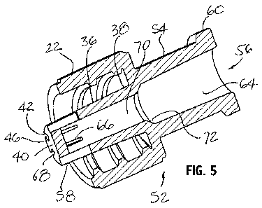
mate with medical devices having companion female luet tapers
SUMMARY
[0004] The various embodiments of the present flushing medical devices and
related
methods have several features, no single one of which is solely responsible
for their desirable
attributes Without limiting the scope of the present embodiments as expressed
by the claims
that follow, their more prominent features now will be discussed briefly After
considering this
discussion, and particularly after reading the section entitled "Detailed
Description," one will
understand how the features of the present embodiments provide advantages,
which include the
capability of providing a wide flow pattern for flushing vascular access
devices
[0005] A flushing medical device comprising a tip for flushing a vascular
access device, such
as a needleless access port valve, a catheter, and a male Luer connector, is
provided In one
example, a tip having body is provided comprising a tip end that is generally
orthogonal to a side
wall having a Luer taper and wherein the tip end and the side wall define an
intersection
therebetween In one example, the side wall has a greater surface area than a
surface area on the
tip end The device further includes a lumen formed by the side wall and
wherein two or more
spaced-apart cut-outs are formed through the side wall and through at least
part of the
intersection In another example, only one cut-out is formed through the side
wall and through at
least part of the intersection
1
CA 02826206 2013 07 31
WO 2012/113865
PCT/EP2012/053070
[0006] Further in accordance with the present device, a receiving end
located opposite the tip
end is provided, the receiving end having an interior wall surface with a
female Lupe! taper.
[0007] The flushing medical device can further include a tapered skirt
section and a flange
defining a notch therebetween and on the body. A collar may be located at the
notch The collar
can be rotatable relative to the body. The flushing medical device, however,
can be practiced
without the collar
[0008] The flushing medical device with the flushing tip can be part of a
syringe and
attached to a syringe barrel and having a plunger having a push flange
slidably disposed therein
The syringe barrel can have different volumetric sizes
[0009] To cover the tip, such as during packaging and/or shipping, a cap
can be fitted over
the tip The cap can also threadedly engage the threaded collar
100101 The flushing medical device can further include cut-outs formed on
the surface area
of the tip end The cut-outs can have various shapes, such as a trapezoidal
shape, a generally
rectangular shape, a square shape, a spiral shape, and slanted shape
[0011] The flushing medical device can optionally include a perimeter
defining an opening
formed only on the surface area of the tip end The opening can function as an
additional flow
port or channel or for use to accommodate a spike of a needleless access port
valve
100121 Another flushing medical device example is one that includes a tip
having a body
comprising a tip end that is generally orthogonal to a side wall having a Luer
taper, wherein the
tip end and the side wall define an intersection therebetween and wherein the
side wall has a
greater surface area than a surface area on the tip end A lumen is formed by
the side wall and a
receiving end having a female Luer taper is disposed at an end opposite the
tip end A threaded
collar can be located exteriorly of the body and wherein two or more spaced-
apart cut-outs are
formed through the side wall and through at least part of the intersection In
another example,
only a single flow channel is formed through the sidewall
[0013] Yet another flushing medical device example is one that includes a
tip having a body
comprising a tip end that is generally orthogonal to a side wall having a Luer
taper, wherein the
tip end and the side wall define an intersection therebetween and wherein the
side wall has a
greater- surface area than a surface area on the tip end A lumen is formed by
the side wall and a
barrel is attached to the tip A plunger is slidably disposed inside the barrel
and wherein two or
2
CA 02826206 2013 07 31
WO 2012/113865 PCT/EP2012/053070
more spaced-apart cut-outs are formed through the side wall and through at
least part of the
intersection..
[0014] The present application further includes a method for flushing a
vascular access
device The method comprising pressing a plunger into a syringe barrel OT
pumping by means of
an automated infusion device; discharging a single flow stream into a flushing
medical device;
and discharging multiple streams out of multiple flow channels at a tip of the
flushing medical
device In another example, a flow stream is discharged out a single flow
channel and wherein
the single flow channel is formed as a cut-out through the side wall of the
tip
BRIEF DESCRIPTION OF THE DRAWINGS
100151 The various embodiments of the present apparatus, systems, and
associated methods
now will be discussed in detail with an emphasis on highlighting the
advantageous features
These embodiments depict the novel and non-obvious apparatus shown in the
accompanying
drawings, which are for illustrative purposes only. These drawings include the
following figures,
in which like numerals indicate like parts:
[0016] FIG 1 shows a perspective view of a syringe having a syringe tip
with multiple flow
channels;
100171 FIG 2 is a side cross-sectional, partial perspective, view of the
syringe of FIG 1;
[0018] FIG 3 is a perspective view of an alternative syringe having a
syringe tip with
multiple flow channels and a central flow port;
[0019] FIG 3A is a fiont view of a syringe tip provided in accordance with
an alternative
example;
[0020] FIG 4 shows a perspective view of a flushing tip adaptor provided in
accordance
with the aspects of the present device, system, and method;
[0021] FIG..5 is a side cross-sectional, partial perspective, view of the
flushing tip adaptor of
FIG 4;
100221 FIG 6 is a perspective view of the flushing tip adaptor of FIG.,4
fiom a rear angle;
[0023] FIG 7 is a perspective view of the flushing tip adaptor of FIG 4
fiom another angle;
[0024] FIG 8 is a perspective view of an alternative flushing tip adaptor
having multiple
flow channels and a central flow port;
3
CA 02826206 2013 07 31
WO 2012/113865 PCT/EP2012/053070
[0025] FIG 9 is a side cross-sectional, partial perspective, view of the
flushing tip adaptor of
FIG 8;
[0026] FIG 10 is a perspective view of another alternative flushing tip
adaptor having
multiple flow channels;
[0027] FIG 11 is a perspective view of yet another alternative flushing tip
adaptor having
multiple flow channels;
[0028] FIG 12 is a perspective view of still yet another alternative
flushing tip adaptor
having multiple flow channels;
[0029] FIG 13 is a perspective view of still yet another alternative
flushing tip adaptor
having multiple flow channels;
[0030] FIG 14 is a perspective view of still yet another alternative
flushing tip adaptor
having multiple flow channels;
[0031] FIG 15 is a cross-sectional side view of an alternative flushing tip
adaptor having a
rotatable threaded collar provided in accordance with the aspects of the
present device, system,
and method;
[0032] FIG. 16 is a side view of the flushing tip adaptor of FIG 15 shown
without the
rotatable threaded collar;
[0033] FIG 17 is across-sectional side view of a cap;
[0034] FIG 18 is a cross-sectional side view of a catheter comprising a
valve and a valve
actuator and having a flushing tip adaptor engaged at a proximal end for
opening the valve and
flushing the catheter; and
[0035] FIG 19 is a schematic flow diagram showing a method for using a
flushing medical
device in accordance with aspect of the present method
DETAILED DESCRIPTION
100361 The detailed description set forth below in connection with the
appended drawings is
intended as a description of the presently preferred embodiments of flushing
medical devices,
such as syringes and flushing tip adaptors, provided in accordance with
aspects of the present
device, system, and method and are not intended to represent the only forms in
which the present
device, system, and method may be constructed or utilized The description sets
forth the
4
CA 02826206 2013-07-31
WO 2012/113865 PCT/EP2012/053070
features and the steps for constructing and using the flushing medical devices
of the present
device, system, and method in connection with the illustrated embodiments It
is to be
understood, however, that the same or equivalent functions and structures may
be accomplished
by different embodiments that are also intended to be encompassed within the
spirit and scope of
the present device, system, and method As denoted elsewhere herein, like
element numbers are
intended to indicate like or similar elements.
[0037] As discussed herein, the word "proximal" is intended to designate an
end of a device
closer to the user than to the patient, when in normal use. The word "distal"
is intended to
designate an end the device closer to the patient than to the user. Unless the
context indicates
otherwise, the words "proximal" and "distal" do not require most proximal end
point or most
distal end point, although such end points fall within the scope of the
respective words
[00381 FIG 1 shows a perspective view of a syringe 10 provided in
accordance with aspects
of the present device, system, and method. In one embodiment, the syringe 10
comprises a
barrel 12 having a gripping flange 14 at a proximal end 16 and a syringe tip
18 at a distal end 20,
which is preferably a Luer tip for mating engagement with a female Luer, such
as a catheter hub,
a needleless port access valve, a male Luer connector, and the like Exemplary
needleless port
access valves are disclosed in U.S.Pat Nos 5,439,451 and 5,700,248, which are
expressly
incorporated herein by reference for all purposes Exemplary male Luer
connectors are disclosed
in U.S Pat Nos. 6,964,406 and 7,803,140, the contents of which are expressly
incorporated
herein by reference for all purposes Exemplary catheter assemblies ate
disclosed in U S. Pat
Nos. 7,736,339; 7,374,554; 7,625,360; 5,879,337; and 6,629,959 and in
publication No WO
2010/093792 Al, filed February 11, 2010; the contents of which are expressly
incorporated
herein by reference for all purposes
[0039] As shown, the syringe 10 includes a collar 22 with internal threads
24 for use as a
Luer lock However, the syringe 10 may be practiced without the threaded
collar, for use as a
Luer slip A piston or plunger 26 have a plunger tip 34 (FIG 2) and a push
flange 28 is slidably
positioned inside the syringe barrel for aspirating or expelling fluids from
the barrel In one
example, the plunger 26 is made fiom a plurality of longitudinal ribs 30 and
radial ribs 32 (FIG
2) In another example, the plunger is made from a central core or rod with one
or more ribs and
without a plunger tip In other words, the plunger stem and plunger tip are
integrally formed and
CA 02826206 2013 07 31
WO 2012/113865 PCT/EP2012/053070
is commonly referred to as a two-piece syringe in the industry. The syringe of
FIG 2 is
commonly referred to as a three-piece syringe in the industry
[0040] The syringe 10 may be made from a number of known prior art plastic
materials
using known methods The syringe 10 is preferably made from a transparent or
semi-transparent
material to permit viewing through the syringe barrel Less preferred, the
syringe barrel is made
from an opaque material Graduated marks, scale, logo, and/or other indicia,
such as lot number,
may be printed on the outside of the syringe barrel for reference purposes
[0041] With reference to FIG 2 in addition to FIG 1, the syringe tip 18
comprises an
elongated body 36 comprising a base 38 connected to the distal end of the
syringe barrel and a
tip end 40 having a generally planar end surface, which may be practiced with
an arc or taper. In
the example shown, a central section 44 of the tip end 40 is solid and does
not incorporate a
lumen Instead, multiple flow channels 42 are incorporated radially of the
central portion 44 In
one example, the flow channels 42 are each generally rectangular or
rectilinear in shape and
includes at least a cut-out formed on or through the tip end 40 More
preferably, each flow
channel 42 is formed by a cut-out formed through both the tip end 40 and the
tip body 36, at the
intersection thereof. Although six flow channels 42 are shown, fewer or more
than six flow
channels may be incorporated
[0042] In one specific example, each flow channel 42 is formed at or
through the intersection
46 of the tip end 40 and the tip body 36 so that when fluid is expelled
through the syringe tip,
fluid flows axially, radially, both axially and radially, and/or randomly
However, each flow
channel 42 may be formed by providing a cut-out through the tip end only and
not the tip body
so that when fluid is expelled through the syringe tip, fluid flows axially
only through the
plurality of axial cut-outs One or more protrusions or projections (not shown)
may be
incorporated at the tip end 40 for the axial only flow embodiment to avoid
sealing or obstructing
the flow channels 42, such as when the tip end abuts a flat surface that can
potentially seal the
axial only flow channels. As further discussed below, fluid discharging
through the tip of the
present syringe has a generally large flow pattern compared to the flow
pattern of a prior art
syringe having a single central lumen
[0043] Refer now to FIG 3, a perspective view of an alternative syringe 48
is shown having
a syringe tip 18 with multiple flow channels 42 and a generally centrally
located port 50 The
6
CA 02826206 2013 07 31
WO 2012/113865 PCT/EP2012/053070
centrally located port 50 may have a circular shape and may vary in diameter
relative to the
radially located flow channels 42 For example, if more fluid flow is intended
to flow through
the radially located flow channels 42, then the central port 50 may have a
relatively smaller
diameter than when less fluid flow is intended to flow through the radially
located flow channels
42 In other embodiments, the centrally located flow port 50 has a non-
circular shape OT
configuration, such as rectangular, oval, triangular, irregular, etc., and may
be located off-center
on the tip end 40 Additionally, one or more protrusions may be incorporated at
the tip end to
prevent sealing the central port 50 and the flow channels 42 against a
generally planar surface
[0044] In yet another embodiment, the central port 50 is sized to
accommodate a spike
located inside a seal of a needless access port valve, such as those shown in
US Pat No
5,700,248 When inserted into the Luer inlet of a needleless access port valve
of the '248 patent,
the tip 18 of the syringe pushes down on the seal of the needleless access
port valve to open the
seal while the central port 50 surrounds the spike to accommodate its presence
fluid flow
discharging from the syringe would then flow through the various radially
located flow channels
42 in flow pattern that is larger than a typical syringe to flush the interior
surfaces of the
needleless access port device
[0045] The syringe of FIGs 1-3 may be used by inserting the tip of the
syringe into a
vascular access device, such as into a female Luer connector of a catheter hub
OT a needleless
access port valve, and, if the syringe has a threaded collar, rotating the
syringe barrel to engage
the collar with the threads on the vascular access device The plunger on the
syringe is then
pushed to expel fluid out of the syringe tip As the tip of the present syringe
has multiple
channels compared to a single lumen on a prior art syringe tip, fluid is
expelled radially, axially,
and/or randomly through the vascular access device to flush most, if not all,
crevices of the
internal chamber of the vascular access device The flow channels of the
disclosed syringes may
also incorporate different shapes or configurations than shown, as further
discussed below with
reference to the various flushing tip adaptors
[0046] FIG 3A is a front view of an alternative syringe tip 18 provided in
accordance with
aspects of the present device The syringe tip comprises a tip body 36 having a
thickness and a
tip end 40 connected to the tip body 36 by a pair of ribs or bridges 200 The
tip end 40 and the
bridges 200 define or form two opening passages 202 at the end of the tip
Fluid discharged
7
CA 02826206 2013-07-31
WO 2012/113865 PCT/EP2012/053070
through the tip 18 is configured to flow through the two passages 202 to
produce a flow pattern
To increase surface area of the two opening passages 202, one or more optional
undercuts 204
may be formed on the interior surface 206 of the tip body 36 The syringe tip
18 of the present
embodiment can therefore provide a larger flow profile or pattern than a
comparable single
lumen prior art syringe.
[0047] FIG
4 shows a perspective view of a flushing tip adaptor 52 provided in accordance
with the aspects of the present device, system, and method As shown, the
flushing tip adaptor
52 comprises a body 54 having a receiving end 56, a proximal end 16, a tip 58
at a distal end 20,
and a threaded collat. 22 having internal threads located between the tip and
the receiving end
The tip is preferably fotmed with a Luer taper tot engaging a female Luer A
plurality of spaced
apart projections 62 may be incorporated at the exterior surface of the
threaded collar 22 to
facilitate gripping the flushing tip adaptor Preferably, the projections are
equally spaced along
the exterior surface Alternatively, round or semi-spherical projections, such
as bumps, are
incorporated instead of elongated projections The bumps may be randomly formed
on the
exterior surface or in an array. As shown, external threads 60 are
incorporated at the proximal
end 16 to provide a female Luer lock, as further discussed below.
[0048]
With reference to FIG 5 in addition to FIG 4, the receiving end 56 comprises a
female Luer taper 64 and is configured to engage a male implement, such as a
syringe tip The
receiving end 56 extends axially and reduces to a smaller nozzle 70 by a
reducer or neck section
72. The smaller port is formed externally with a male Luer taper If the male
implement (not
shown) has a threaded collar, it may engage the exterior threads 60 and
threadedly lock to the
proximal end of the flushing tip adaptor. The tip 58 and the collar 22 are
shown singularly
fabricated to the receiving end 56 However, the collar may be eliminated
altogether or
separately formed and subsequently attached to the body 54, as further
discussed below.
[0049] The
tip 58 is similar to the tip 18 shown in FIG 1 and comprises a tip body 36, a
tip
base 38, a tip end 40, an intersection 46 between the tip end and the tip
body, and a plurality of
flow channels 42 As clearly shown, the flow channels 42 each include an axial
cut-out section
66 and a radial cut-out section 68 and a planar tip end 40 that is generally
solid, i e , without a
central lumen
8
CA 02826206 2013-07-31
WO 2012/113865
PCT/EP2012/053070
[0050] The flushing tip adaptor 58 is configured for use with a standard
syringe having a
standard Luer tip, either with or without a threaded collar For example, the
syringe tip (not
shown) may be inserted into the receiving end 56 and held secured thereto by
the Luer taper, or
optionally with the threaded collar engaging the exterior threads 60. Once
connected, the
combination standard syringe (not shown) and flushing tip adaptor 58 is
configured to perform
the same or similar flushing function as discussed above for the FIGs 1-3
syringes More
particularly, the flushing tip adaptor is configured to convert a single axial
flow from a lumen of
a standard syringe tip and diverting the flow into a plurality of flow streams
that include axial,
radial, both axial and radial, and/or random flow streams. The flow streams
also collectively
produce a flow pattern that is larger than the flow pattern of a typical prior
art syringe having a
single central lumen In particular, the typical prior art syringe has a
central opening and has a
tendency to create a dead cornet between the very distal end of the male Luer
tip and the side
wall of the female Luer taper The present device is configure to eliminate
this dead corner and
directs flushing flow directly at the surfaces to reach this dead corner
[0051] As shown in FIGs 4 and 5 and as described, the flushing tip adaptor
58 is understood
to include a body having a receiving end formed with a female Luer connector
having a first
interior diameter and a nozzle having a second inside diameter smaller than
the first diameter
with a plurality of flow channels formed at the distal end of the nozzle for
diverting a single flow
stream to multiple streams when exiting the nozzle In one embodiment, the
multiple streams
include axial flow streams, radial flow streams, both axial and radial flow
streams, and/or
random streams. Thus, when used with a vascular access device, the multi-
direction streams
flow through most if not all of the sections or crevices of the vascular
access device to flush the
device In a specific example, fluid flow out the Luer tip include streams that
flow radially
outwardly of the intersection 46 of the syringe tip In comparison to a
standard male Luer tip,
the instant flushing tip adaptor 52 is configured to produce a wider spray or
flow pattern than a
single flow stream out a central lumen
[0052] FIG. 6 is a perspective view of the flushing tip adaptor 52 of FIG 4
viewed from a
rear angle
100531 FIG 7 is a perspective view of the flushing tip adaptor 52 of FIG 4
viewed from
another angle and looking at the tip The flushing tip adaptor 52 may be made
from a number of
9
CA 02826206 2013-07-31
WO 2012/113865 PCT/EP2012/053070
prior art plastic materials, such as PP, HDPE, PC, ABS, etc The walls of the
flushing tip
adaptor may be opaque, semi-opaque, or transparent
10054] FIG 8 is a perspective view of an alternative flushing tip adaptor
72 having a tip 74
with multiple flow channels 42 and a central flow port 50. The tip 74 is
similar to the tip of FIG
3 in that it has both a central flow port 50 and radially located flow
channels 42.
[0055] FIG..9 is a side cross-sectional, partial perspective, view of the
flushing tip adaptor 72
of FIG 8 Axial cut-out sections 66 and radial cut-out sections of the flow
channels 42 are
clearly shown along with part of the central flow port 50
[0056] F 1G.10 is a perspective view of another alternative flushing tip
adaptor 78 having a
tip 80 with two flow channels 42 formed through the tip end 40 and the tip
body 36, and in
particular through the intersection 46 The two flow channels 42 may be equally
spaced apart
along the perimeter of the tip at the intersection 46. However, more than two
flow channels or a
single flow channel may be incorporated without deviating from the present
device Although
not shown, a central port 50 may be incorporated By incorporating the instant
flow channels at
the tip, the adaptor is configured to produce a wider spray Or flow pattern
than a single flow
stream out a central lumen of a typical prior art syringe
[0057] FIG II is a perspective view of yet another alternative flushing tip
adaptor 82 having
a tip 84 with multiple flow channels 86 and a threaded collar 22, which may
optionally be
omitted The tip preferably has a body 36 formed with a Luer taper and the flow
channels 86
each includes an axial cut-out and a radial cut-out However, unlike the flow
channels of, for
example, FIGs 3 and 8, the cut-outs are slanted relative to a central axis of
the flushing tip
adaptor 82, which is generally in the direction between the proximal and
distal ends For
example, each axial cut-out 66 has two side walls that are generally parallel
to one another but
are angled relative to the central axis of the flushing tip adaptor 82. The
bottom wall, located
between the two side walls, may be perpendicular to the side walls or angled
relative thereto In
other examples, the two side walls are not parallel to one another, as further
discussed below
Although six flow channels 86 are shown, fewer or more than six flow channels
may be
incorporated Also, a central port 50 may be incorporated
[0058] In one example, each flow channel 86 has a radial cut-out 68 with
two side walls that
are generally parallel to one another and point generally to a central point
on the tip end 40 In
CA 02826206 2013 07 31
WO 2012/113865 PCT/EP2012/053070
another example, the side walls point tangentially to the central point on the
tip end 40 so that the
multiple radial cut-outs are all slanted In still other examples, the cut-outs
are randomly formed
along the intersection 46 with both radial and axial cut-outs Less preferably,
the cut-outs are
randomly formed near the intersection 46 of the tip with only radial cut-outs
68 By
incorporating the instant flow channels at the tip, the adaptor is configured
to produce a wider
spray or flow pattern than a single flow stream out a central lumen of a
typical prior art syringe
10059] FIG
12 is a perspective view of still yet another alternative flushing tip adaptor
88
having a tip 90 with multiple flow channels 92 and a threaded collar 22, which
may optionally be
omitted In the present embodiment, the flow channels 92, while including
radial cut-outs and
axial cut-outs formed at the intersection 46, are formed with smooth spiral
curves, which may be
slanted clock-wise or counter-clockwise when viewing the tip 90 from a side
view. Although six
flow channels 92 are shown, fewer or more than six flow channels may be
incorporated Also, a
central port 50 may be incorporated By incorporating the instant flow channels
at the tip, the
adaptor is configured to produce a wider spray or flow pattern than a single
flow stream out a
central lumen of a typical prior art syringe
[0060] In
one example, a method is provided for manufacturing the flushing tip adaptor
comprising injection molding a body having a tip and a collar Forming a
plurality of flow
channels 92 having spiral curves that are slanted in a same clockwise or
counter-clockwise
direction as threads located on the collar 22 Ejecting the flushing tip
adaptor from an injection
pin using a same unscrewing direction for the slanted spiral cutves and the
threads on the collar
[0061] FIG
13 is a perspective view of still yet another alternative flushing tip adaptor
94
having a tip 96 with multiple flow channels 98 and a threaded collar 22, which
may optionally be
omitted In the present embodiment, the flow channels 98, while including
radial cut-outs and
axial cut-outs, are formed with narrowing side walls For example, starting
from the bottom wall
100 of each flow channel 98, the side walls narrow or taper inwardly toward
one another to the
intersection 46 At the intersection 46, the side walls of the radial cut-out
taper inwardly in the
direction of the central point of the tip end 40 Thus, the present flushing
tip adaptor 94 is
understood to include a plurality of flow channels 98 each including a first
trapezoid cut-out
along an axial direction and a second trapezoid cut-out along a radial
direction Wherein the first
trapezoid is larger than the second trapezoid Although six flow channels 98
are shown, fewer or
11
CA 02826206 2013 07 31
WO 2012/113865 PCT/EP2012/053070
more than six flow channels may be incorporated Also, a central port 50 may be
incorporated
By incorporating the instant flow channels at the tip, the adaptor is
configured to produce a wider
spray or flow pattern than a single flow stream out a central lumen of a
typical prim art syringe
[0062] FIG 14 is a perspective view of still yet another alternative
flushing tip adaptor 102
having a tip 104 with multiple flow channels 106 and a threaded collar 22,
which may optionally
be omitted In the present embodiment, the flow channels 106, while including
radial cut-outs
and axial cut-outs, are formed with enlarging or diverging side walls For
example, starting from
the bottom wall 100 of each flow channel 106, the side walls diverge or taper
outwardly away
one another to the intersection 46 At the intersection 46, the side walls of
the radial cut-out
taper outwardly in the direction of the central point of the tip end 40 Thus,
the present flushing
tip adaptor 94 is understood to include a plurality of flow channels 106 each
including a first
trapezoid cut-out along an axial direction and a second trapezoid cut-out
along a radial direction
Wherein the first trapezoid is smaller than the second trapezoid Although six
flow channels 106
are shown, fewer or more than six flow channels may be incorporated. Also, a
central port 50
may be incorporated By incorporating the instant flow channels at the tip, the
adaptor is
configured to produce a wider spray or flow pattern than a single flow stream
out a central lumen
of a typical prior art syringe
[0063] FIG 15 is a cross-sectional side view of an alternative flushing tip
adaptor 108
having a tip 110 with multiple flow channels 112 having a rotatable threaded
collar 114 provided
in accordance with the aspects of the present device, system, and method The
flushing tip
adaptor 108 is similar to the flushing tip adaptor 52 of FIGs 4-7 with the
exception of the
rotatable collar relative to the tip body 54 and the receiving end 56 is sized
to receive a tubing
Such as a device is commonly tefetred to as an adaptor for a drip line OT
extension line
However, the receiving end may incorporate a female Luet taper In the present
example, a
tapered skirt section 116 and a flange 118 are provided on the exterior
surface of the tip body to
define a notch 120 therebetween The collar has a bottom 122 with an opening
124 sized to slide
over the tapered skirt section 116 and retained at the notch 120 A curved or
arcuate nose section
126 of the opening 124 is provided to facilitate assembly of the collar 114
over the taper skirt
section 116 Once installed, the collar is retained within the notch and is
rotatable relative to the
tip 110 or the body of the tip, which has the plurality of flow channels 112
Although the axial
12
CA 02826206 2013-07-31
WO 2012/113865 PCT/EP2012/053070
cut-outs 66 appear generally rectangular., the cut out configuration can
embody a number of
different shapes, such as those discussed above.
[0064] FIG 16 is a side view of the flushing tip adaptor 108 of FIG 15
shown without the
rotatable threaded collar 114 A plurality of spaced-apart gripping members 128
may be
incorporated on the exterior surface of the body 130 to facilitate gripping.
Although shown as
equally spaced apart elongated beams, the gripping members may have other
shapes, such as
round or semi-spherical projections In one example, the flushing tip adaptor
108 is practiced
without the collar.
[0065] To use the alternative flushing tip adaptor 108, the tip 110 is
first inserted into a
female receiving end of a vascular access device, such as a catheter, and then
rotating the collar
relative to the body 130 to engage external threads located on the vascular
access device
Preferably, a tubing is first attached to the receiving end 56 of the body 130
before connecting
the flushing tip adaptor 108 to the vascular access device If the receiving
end 56 is equipped
with a female Luer, then the receiving end can be connected to a standard
syringe
[0066] FIG. 17 is a cross-sectional side view of a cap 132 provided in
accordance with aspect
of the present device, system, and method. The cap is shown with a body 134
having a base with
threads 136 for threaded engagement with a collar. The cap 132 further
comprises a vent
opening 138 to permit capping a tip, such as on a syringe or a flushing tip
adaptor described
elsewhere herein, and avoiding air lock The cap is sized to receive a luer tip
[0067] FIG 18 is a cross-sectional side view of a catheter 140 attached to
a flushing tip
adaptor 142, which represents the flushing tip adaptor when in normal use, but
without a syringe
or other fluid source, such as a drip line, typically attached to the
receiving end 56 of the flushing
tip adaptor. The catheter is shown without a needle, a needle hub, and a
needle guard and is
therefore representative of a catheter following successful catheterization
Exemplary safety
intravenous catheters or IVCs are disclosed in patent numbers 7,736,339;
7,374,554; '7,625,360;
5,879,337; and 6,629,959 and in publication No WO 2010/093792 Al, filed
February 11, 2010;
the contents of each of the foregoing are expressly incorporated herein by
reference. The
disclosed tip adaptors discussed herein are usable with any of the
incorporated catheter
assemblies Alternatively, the syringe of F. IGs 1-3 may be connected directly
to the catheter
without the tip adaptor.
13
CA 02826206 2013 07 31
WO 2012/113865 PCT/EP2012/053070
[0068] As shown, the catheter 140 comprises a catheter hub 144, a catheter
tube 146, an
openable and closeable valve 148, and a valve actuator 150 Similar catheter
assemblies are
described in US Pat No 7,736,339 In a normal closed or sealed state without
the flushing tip
adaptor engaging the catheter, the valve actuator 150 is pushed to the right
of FIG 18 by the
resiliency of the valve 148 and the valve flaps are generally positioned
vertically to close the
flow opening 152 Upon insertion of the tip adaptor 142, the tip end 40 of the
tip abuts the valve
actuator 150 and pushes the actuator into the valve 148 to open the valve, as
shown in FIG 18
In the open state as shown, fluid that is discharged through the tip flows
through a plurality of
flow channels 154 in a large flow pattern 156, indicated by the flow arrows
distal of the tip The
large flow pattern 156 allows the interior chamber 160 to be flushed with
fluids flowing from the
syringe or flushing tip adaptor As a comparison, a prior art syringe is more
likely to produce a
flow pattern that is represented by the two interior arrows 156 only since
fluid fiom the prior art
syringe would flow from a single central lumen located in the syringe tip
Hence, less or smaller
areas of the interior chamber of the catheter hub 144 will be flushed from the
smaller flow
pattern as compared to the flow pattern generated by the medical flushing
device of the present
assembly and method The flow channels 154 can be sized to facilitate flushing
of a groove in
the side of the female luer, where the legs of the valve opener were
previously located before
they were pushed forward by the male luer tip Likewise, the flow channels 154
can be sized
narrower than the legs of the valve opener so that the push forward to open
the valve is contacts
at least part of the tip end
100691 FIG 19 is a schematic flow diagram showing a method 164 for using a
flushing
medical device in accordance with aspects of the present method In one
example, the method
comprises connecting a flushing medical device to a vascular access device at
step 166. The
method further comprising discharging or allowing fluid through the medical
flushing device at
step 168 For example, pushing or exerting pressure on a plunger to discharge
fluid through a
barrel of a syringe to exit through the medical flushing device Alternatively,
allowing fluid to
flow by gravity or a pressure differential generated by an automated infusion
device As
discussed above, the syringe itself may include a tip having multiple flow
channels each
comprising a radially located cut-out and an axially located cut-out and
itself a flushing medical
device Alternatively, a flushing tip adaptor may be connected to the vascular
access device and
14
CA 02826206 2013 07 31
WO 2012/113865
PCT/EP2012/053070
a prefilled syringe is connected to it Fluids usable with the present method
include Antibiotics
(such as Cefuroxime, Ceftriaxone, Meropenem, Imipenem, Amoxicillin, Pip/Corn
Pip/'Tazo,
Ciprofloxacin, Levofioxacin, Moxifloxacin, Metronidazol, Vancomycin, and
Daptomycin),
Antimycotics (such as Huconazol Amphotericin B, and Caspofungin), Virustatics
(such as
Gangciclovir and Foscavir), longterm infusion fluid (such as KCL, Propofol,
Sufentanil, Insulin,
Midazolam, Nimodipin, Heparin, Furosemid, Glutamin, Hydrocortison, Ketamin,
Amiodaron,
Danaparoid, Milrinon, and Glyceroltrinitrat), Cathecholamine (such as
Noradrenalin,
Athenalin, Dopamin, and Dobutamin), and Emergency set (such as Noradrenalin,
Adrenalin,
Morphin, and Sufentanil)
[0070] The method further comprising the step of producing a spray pattern
at the tip of the
flushing medical device at step 170 The spray pattern is larger than a typical
pattern produced
by a prior art tip having a single central lumen As discussed above, the spray
pattern can be
produced by a plurality of flow channels and an optional central port The flow
pattern can be
influenced by the size of each flow channel and the flow channel
configuration, such as
rectangular, trapezoidal, spiral, etc The method further comprises the step
172 of flushing the
vascular access device with the produced spray pattern The spray pattern is
configured to flush
more interior surface area of the vascular access device than for the flow
produced from a tip
having a single central lumen
[0071] In another embodiment, a syringe having the disclosed tip with
multiple flow
channels and spray pattern is used to wet bandages For a single fluid
discharge through the tip
of the present device, more surface area of a bandage is wet compared to a
single fluid discharge
out a tip having a single central lumen
[0072] Although limited embodiments of syringe assemblies, flushing tip
adaptors, and their
components have been specifically described and illustrated herein, many
modifications and
variations will be apparent to those skilled in the art Furthermore, it is
understood and
contemplated that features specifically discussed for one medical flushing
device may be adopted
for inclusion with another medical flushing device provided the functions are
compatible For
example, certain flow channel configuration or shape from one tip adaptor may
be combined
with another flow channel configuration to have multiple flow configurations
on a single
flushing tip Accordingly, it is to be understood that the syringe assemblies,
flushing tip
CA 02826206 2013 07 31
WO 2012/113865
PCT/EP2012/053070
adaptors, and their components constructed according to principles of the
present device, system,
and method may be embodied other than as specifically described herein. The
invention is also
defined, at least in part, in the following claims
16